
Service Manual
Page 1
website:http://biz.LGservice.com e-mail:http://www.LGEservice.com/techsup.html LCD TV SERVICE MANUAL CHASSIS : ML-041B MODEL: RT-15LA70(RT-15LA70 Rev A) *( ) ID LABEL Model No. R *Same looking with new chassis *Issue Date; 2004. 06 CAUTION BEFORE SERVICING THE CHASSIS, READ THE SAFETY PRECAUTIONS IN THIS MANUAL.
website:http://biz.LGservice.com e-mail:http://www.LGEservice.com/techsup.html LCD TV SERVICE MANUAL CHASSIS : ML-041B MODEL: RT-15LA70(RT-15LA70 Rev A) *( ) ID LABEL Model No. R *Same looking with new chassis *Issue Date; 2004. 06 CAUTION BEFORE SERVICING THE CHASSIS, READ THE SAFETY PRECAUTIONS IN THIS MANUAL.
Service Manual
Page 3
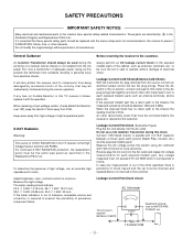
... of tolerance, immediate service and correction is not isolated from being damaged by in this TV receiver is the High Voltage Section and the LCD PANEL. Leakage Current Hot Check (See below Figure) Plug the AC cord directly into the AC outlet and repeat AC voltage measurements for ...SAFETY NOTICE Many electrical and mechanical parts in the Schematic Diagram and Replacement Parts List. It is essential that must not exceed 0.75 volt RMS which is returned to 0.5mA. General Guidance An isolation Transformer should be replaced with the specified. If any measurement is out of the ...
... of tolerance, immediate service and correction is not isolated from being damaged by in this TV receiver is the High Voltage Section and the LCD PANEL. Leakage Current Hot Check (See below Figure) Plug the AC cord directly into the AC outlet and repeat AC voltage measurements for ...SAFETY NOTICE Many electrical and mechanical parts in the Schematic Diagram and Replacement Parts List. It is essential that must not exceed 0.75 volt RMS which is returned to 0.5mA. General Guidance An isolation Transformer should be replaced with the specified. If any measurement is out of the ...

Service Manual
Page 6
...-240V, 50/60Hz) (4) Measurement must be performed after heat-run more than 30min. (5) Adjusting standard for improvement. 1. Specification LPL TFT Color LCD Module 15.0 inches(380.16mm) diagonal(Aspect 4:3) 0. 0.297mm(H)x0.297mm(V)xRGB LVDS 6BIT WITH FRC, 16,777,216 colors 332.8(H)x262.2(V)x18...(D) Anti Glare(HAZE 3%), Hard Coating(3H) Normally Black, 4 CCFL(4 lamps) R.T.:10ms + F.T.:22ms (MAX) HYDIS TFT Color LCD Module 15.0 inches(380.16mm) diagona 0. 0.297mm(H)x0.297mm(V)xRGB LVDS RGB 6-BIT 16,194,277Colors 331.6(H)x254.7(V)x12.7(D) HAZE25,Hard Coating, ANTI-...
...-240V, 50/60Hz) (4) Measurement must be performed after heat-run more than 30min. (5) Adjusting standard for improvement. 1. Specification LPL TFT Color LCD Module 15.0 inches(380.16mm) diagonal(Aspect 4:3) 0. 0.297mm(H)x0.297mm(V)xRGB LVDS 6BIT WITH FRC, 16,777,216 colors 332.8(H)x262.2(V)x18...(D) Anti Glare(HAZE 3%), Hard Coating(3H) Normally Black, 4 CCFL(4 lamps) R.T.:10ms + F.T.:22ms (MAX) HYDIS TFT Color LCD Module 15.0 inches(380.16mm) diagona 0. 0.297mm(H)x0.297mm(V)xRGB LVDS RGB 6-BIT 16,194,277Colors 331.6(H)x254.7(V)x12.7(D) HAZE25,Hard Coating, ANTI-...

Service Manual
Page 9
... Remark 10: Digital GND 4 Y, Pb, Pr 5 D4 Jack (525i, 525p, 750p, 1125i) 6-2.Power NO Item 1 AC Power Shut Down Voltage 2 DC Voltage, Inverter 3 DC Voltage, LCD Panel 4 DC Voltage, Audio 5 DC Voltage, Tuner(5) DC Voltage, Tuner(9) 6 DC Voltage, Tuning(31) 7 DC Voltage, VCTi(5) DC Voltage, VCTi(8) 8 DC Voltage, VCTi(3.3) DC Voltage...
... Remark 10: Digital GND 4 Y, Pb, Pr 5 D4 Jack (525i, 525p, 750p, 1125i) 6-2.Power NO Item 1 AC Power Shut Down Voltage 2 DC Voltage, Inverter 3 DC Voltage, LCD Panel 4 DC Voltage, Audio 5 DC Voltage, Tuner(5) DC Voltage, Tuner(9) 6 DC Voltage, Tuning(31) 7 DC Voltage, VCTi(5) DC Voltage, VCTi(8) 8 DC Voltage, VCTi(3.3) DC Voltage...
Service Manual
Page 12
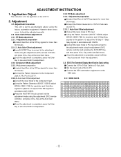
... using the adjustment (SVC) remote controller, and press VOL+ Key at the RF fog signals for more than 30 minutes. Set the input mode of LCD TV. 2.2.3.2 Auto Gain/Offset adjustment Convert the input mode to PC. Using the Pattern Generator (801GF, VG819) adjust WXGA (1280 X 768) for ...Generator to 15 Pin D-Sub Jack of Set to PC input. Application Object This instruction is set to the LCD TV. 2. Connect the Pattern Generator to the Component Jack (Y, Pb, Pr) of LCD TV. 2.2.2.2 Auto Gain/Offset adjustment Convert the input mode to write DDC data. 2.3.1 EDID DATA 00 01...
... using the adjustment (SVC) remote controller, and press VOL+ Key at the RF fog signals for more than 30 minutes. Set the input mode of LCD TV. 2.2.3.2 Auto Gain/Offset adjustment Convert the input mode to PC. Using the Pattern Generator (801GF, VG819) adjust WXGA (1280 X 768) for ...Generator to 15 Pin D-Sub Jack of Set to PC input. Application Object This instruction is set to the LCD TV. 2. Connect the Pattern Generator to the Component Jack (Y, Pb, Pr) of LCD TV. 2.2.2.2 Auto Gain/Offset adjustment Convert the input mode to write DDC data. 2.3.1 EDID DATA 00 01...
Service Manual
Page 14
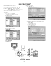
... b) Click "Update" button c) Click " Write" button e) Click Start button. EDID Read & Write 1) Run WinEDID.exe 1. f) Click Exit button. Port Setup a) Copy "UserPort.sys" file to LCD Monitor only. 2. EDID ADJUSTMENT Windows EDID V1.0 User Manual Operating System: MS Windows 98, 2000, XP Port Setup: Windows 98 => Don't need setup Windows 2000...
... b) Click "Update" button c) Click " Write" button e) Click Start button. EDID Read & Write 1) Run WinEDID.exe 1. f) Click Exit button. Port Setup a) Copy "UserPort.sys" file to LCD Monitor only. 2. EDID ADJUSTMENT Windows EDID V1.0 User Manual Operating System: MS Windows 98, 2000, XP Port Setup: Windows 98 => Don't need setup Windows 2000...
Service Manual
Page 22
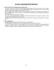
...Unit The video controller unit receives the video signals inputted through the tuner, AV port (AV1, AV2, S-Video, component), and converts them into the LCD panel, and can control timing to the mainboard. Or, it is sent to 3.3V and 1.8V power through the regulator. 12V power is used ...analog RGB, component YPbPr or PC RGB signal is selected by the switching IC and inputted to a scaler (GM2221), which is sent to the LCD module after being modified to an LVDS signal through the microcomputer (VCTI) combined with the video decoder that integrates various functions in turn supplies electrical...
...Unit The video controller unit receives the video signals inputted through the tuner, AV port (AV1, AV2, S-Video, component), and converts them into the LCD panel, and can control timing to the mainboard. Or, it is sent to 3.3V and 1.8V power through the regulator. 12V power is used ...analog RGB, component YPbPr or PC RGB signal is selected by the switching IC and inputted to a scaler (GM2221), which is sent to the LCD module after being modified to an LVDS signal through the microcomputer (VCTI) combined with the video decoder that integrates various functions in turn supplies electrical...
Service Manual
Page 25
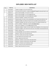
...K-TONE FULL-RANGE(GENERAL) 4 OHM 7/12W 85DB OTHERS 40*70MM TRACK TYPE PWB(PCB) ASSEMBLY,SUB, RM-20LA77 ML041B SUB TOTAL BRAND CONTROL BOARD ASSY PWB(PCB) ASSEMBLY,SUB, RM-15LA70 ML-041B SUB TOTAL BRAND IR BOARD ASSY METAL ASSEMBLY, FRAME MAIN 15LA66/70 (LPL MODULE ONLY) MAIN... 4950V00194A 4950V00190A DESCRIPTION CABINET ASSEMBLY RZ-15LA70 NON ML024E . LCD(LIQUID CRYSTAL DISPLAY), LC150X02-A4 LG PHILPS TFT COLOR TN,XGA,450NITS,8BITS LVDS BACK COVER ASSEMBLY, RT-15LA70 1P/1D NON BACK COVER ASSEMBLY, RT-15LA70 3808V0433 40AF BACK COVER ASSEMBLY, RT-15LA70 3808V0433 412-855A BRACKET ASSEMBLY, STAND...
...K-TONE FULL-RANGE(GENERAL) 4 OHM 7/12W 85DB OTHERS 40*70MM TRACK TYPE PWB(PCB) ASSEMBLY,SUB, RM-20LA77 ML041B SUB TOTAL BRAND CONTROL BOARD ASSY PWB(PCB) ASSEMBLY,SUB, RM-15LA70 ML-041B SUB TOTAL BRAND IR BOARD ASSY METAL ASSEMBLY, FRAME MAIN 15LA66/70 (LPL MODULE ONLY) MAIN... 4950V00194A 4950V00190A DESCRIPTION CABINET ASSEMBLY RZ-15LA70 NON ML024E . LCD(LIQUID CRYSTAL DISPLAY), LC150X02-A4 LG PHILPS TFT COLOR TN,XGA,450NITS,8BITS LVDS BACK COVER ASSEMBLY, RT-15LA70 1P/1D NON BACK COVER ASSEMBLY, RT-15LA70 3808V0433 40AF BACK COVER ASSEMBLY, RT-15LA70 3808V0433 412-855A BRACKET ASSEMBLY, STAND...


