

Owners Manual
Page 1
See the label attached on the back of the Monitor. Model Number : Serial Number : LG Electronics U.S.A., Inc. Retain it for future reference. Record model number and serial number of the Monitor and relate this owner's manual thoroughly before operating the Monitor. PLASMA MONITOR OWNER'S MANUAL MODELS : MU-42PM11/12X/20 MU-50PM10/11/20 Please read this information to your dealer if you ever require service.
See the label attached on the back of the Monitor. Model Number : Serial Number : LG Electronics U.S.A., Inc. Retain it for future reference. Record model number and serial number of the Monitor and relate this owner's manual thoroughly before operating the Monitor. PLASMA MONITOR OWNER'S MANUAL MODELS : MU-42PM11/12X/20 MU-50PM10/11/20 Please read this information to your dealer if you ever require service.

Owners Manual
Page 8
...Monitor on a PC. 3. Never attempt to 'Speaker & Speaker Stand' manual. 9. Connection panels shown may be somewhat different from an S-VIDEO device to these jacks. 6. RS-232C INPUT (CONTROL/SERVICE) PORT Connect to another monitor, connect RGB OUTPUT to the RS-232C... S-Video out from your wired remote control to the remote control port on an AC power. Back Connection Panel REMOTE RS-232C INPUT CONTROL (CONTROL/SERVICE) DVI INPUT AUDIO INPUT RGB INPUT RGB OUTPUT 1 2 3 4 Y PB PR COMPONENT INPUT R L AUDIO INPUT S-VIDEO 5 6 R L (MONO) AUDIO INPUT VIDEO INPUT 7...
...Monitor on a PC. 3. Never attempt to 'Speaker & Speaker Stand' manual. 9. Connection panels shown may be somewhat different from an S-VIDEO device to these jacks. 6. RS-232C INPUT (CONTROL/SERVICE) PORT Connect to another monitor, connect RGB OUTPUT to the RS-232C... S-Video out from your wired remote control to the remote control port on an AC power. Back Connection Panel REMOTE RS-232C INPUT CONTROL (CONTROL/SERVICE) DVI INPUT AUDIO INPUT RGB INPUT RGB OUTPUT 1 2 3 4 Y PB PR COMPONENT INPUT R L AUDIO INPUT S-VIDEO 5 6 R L (MONO) AUDIO INPUT VIDEO INPUT 7...

Owners Manual
Page 12
...connect an S-VIDEO output from VCR to the S-VIDEO input, the picture quality is connected to a cable TV service from a VCR. For further information regarding cable TV service, contact your desired channel with the Monitor VCR Setup - To avoid picture noise (interference), leave an adequate distance ... Select the input source with using the INPUT SELECT button on the remote control. (If connected to the VCR owner's manual.) 4. Select your local cable TV service provider(s). Use the ISM Method (on the Option menu) feature to avoid having a fixed image remain on the VCR....
...connect an S-VIDEO output from VCR to the S-VIDEO input, the picture quality is connected to a cable TV service from a VCR. For further information regarding cable TV service, contact your desired channel with the Monitor VCR Setup - To avoid picture noise (interference), leave an adequate distance ... Select the input source with using the INPUT SELECT button on the remote control. (If connected to the VCR owner's manual.) 4. Select your local cable TV service provider(s). Use the ISM Method (on the Option menu) feature to avoid having a fixed image remain on the VCR....

Owners Manual
Page 14
... set -top box.) 2. Turn on the digital set-top box. (Refer to the owner's manual for video connections, depending on the remote control to use 1. Then, make the corresponding audio connections. REMOTE RS-232C INPUT CONTROL (CONTROL/SERVICE) DVI INPUT AUDIO INPUT RGB INPUT RGB OUTPUT Y PB PR COMPONENT INPUT R L AUDIO INPUT...
... set -top box.) 2. Turn on the digital set-top box. (Refer to the owner's manual for video connections, depending on the remote control to use 1. Then, make the corresponding audio connections. REMOTE RS-232C INPUT CONTROL (CONTROL/SERVICE) DVI INPUT AUDIO INPUT RGB INPUT RGB OUTPUT Y PB PR COMPONENT INPUT R L AUDIO INPUT...

Owners Manual
Page 15
PC Setup How to use 1. Owner's Manual 15 Check the image on your PC connector. • If the graphic card on the PC does not output analog and digital RGB simultaneously, connect ... PC graphic card can not be noise associated with the resolution, vertical pattern, contrast or brightness in PC mode. REMOTE CONTROL RS-232C INPUT (CONTROL/SERVICE) DVI INPUT AUDIO INPUT RGB INPUT RGB OUTPUT Installation How to connect 1. Turn on the monitor's screen for a long period of the PC graphic card...
PC Setup How to use 1. Owner's Manual 15 Check the image on your PC connector. • If the graphic card on the PC does not output analog and digital RGB simultaneously, connect ... PC graphic card can not be noise associated with the resolution, vertical pattern, contrast or brightness in PC mode. REMOTE CONTROL RS-232C INPUT (CONTROL/SERVICE) DVI INPUT AUDIO INPUT RGB INPUT RGB OUTPUT Installation How to connect 1. Turn on the monitor's screen for a long period of the PC graphic card...
Owners Manual
Page 29
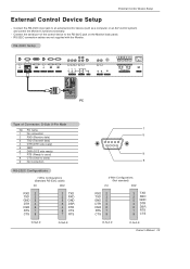
RS-232C connection cables are not supplied with the Monitor. D-Sub 9-Pin Male No. RS-232C Setup REMOTE RS-232C INPUT CONTROL (CONTROL/SERVICE) DVI INPUT AUDIO INPUT RGB INPUT RGB OUTPUT Y PB PR COMPONENT INPUT R L AUDIO INPUT S-VIDEO R L (MONO) AUDIO INPUT VIDEO INPUT ( )R( ) ( )L( ) EXTERNAL SPEAKER AC INPUT PC ... D-Sub 9 D-Sub 9 1 5 9 6 3-Wire Configurations (Not standard) PC PDP RXD 2 TXD 3 GND 5 DTR 4 DSR 6 RTS 7 CTS 8 3 TXD 2 RXD 5 GND 4 DTR 6 DSR 7 RTS 8 CTS D-Sub 9 D-Sub 9 Owner's Manual 29
RS-232C connection cables are not supplied with the Monitor. D-Sub 9-Pin Male No. RS-232C Setup REMOTE RS-232C INPUT CONTROL (CONTROL/SERVICE) DVI INPUT AUDIO INPUT RGB INPUT RGB OUTPUT Y PB PR COMPONENT INPUT R L AUDIO INPUT S-VIDEO R L (MONO) AUDIO INPUT VIDEO INPUT ( )R( ) ( )L( ) EXTERNAL SPEAKER AC INPUT PC ... D-Sub 9 D-Sub 9 1 5 9 6 3-Wire Configurations (Not standard) PC PDP RXD 2 TXD 3 GND 5 DTR 4 DSR 6 RTS 7 CTS 8 3 TXD 2 RXD 5 GND 4 DTR 6 DSR 7 RTS 8 CTS D-Sub 9 D-Sub 9 Owner's Manual 29
Owners Manual
Page 37
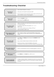
Picture OK & No sound • Press the VOLUME (G) button. • Sound muted? Please contact your service center, if the picture has not appeared after switching on or off and does not indicate a fault with correct polarity (+ to +, - No or ...and the VCR. • Activate any object between the Monitor and the remote control causing obstruction. • Are batteries installed with the Monitor. Owner's Manual 37 The remote control doesn't work • Check to see if there is any function to p.9) Picture appears slowly after five minutes. Troubleshooting Checklist ...
Picture OK & No sound • Press the VOLUME (G) button. • Sound muted? Please contact your service center, if the picture has not appeared after switching on or off and does not indicate a fault with correct polarity (+ to +, - No or ...and the VCR. • Activate any object between the Monitor and the remote control causing obstruction. • Are batteries installed with the Monitor. Owner's Manual 37 The remote control doesn't work • Check to see if there is any function to p.9) Picture appears slowly after five minutes. Troubleshooting Checklist ...

Owners Manual
Page 40
...'s expense. THIS LIMITED WARRANTY DOES NOT APPLY TO: G damage caused in shipping or transit G service required as a result of improper installation, including incorrect or insufficient AC supply (please consult the owner's manual for power supply requirements) G installation or repair of antenna systems, cable converters, cable company supplied ...caused by improper adjustments G damage caused by other system components G any panel that unit in returning the defective unit to the LG®Brand Service Center. Your credit card will be borne by the consumer. If you call .
...'s expense. THIS LIMITED WARRANTY DOES NOT APPLY TO: G damage caused in shipping or transit G service required as a result of improper installation, including incorrect or insufficient AC supply (please consult the owner's manual for power supply requirements) G installation or repair of antenna systems, cable converters, cable company supplied ...caused by improper adjustments G damage caused by other system components G any panel that unit in returning the defective unit to the LG®Brand Service Center. Your credit card will be borne by the consumer. If you call .
Service Manual
Page 1
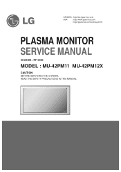
CANADA : http//biz.lgservice.com USA : http//www.lgservice.com : http//lgservice.com/techsup.html PLASMA MONITOR SERVICE MANUAL CHASSIS : RF-043E MODEL : MU-42PM11 MU-42PM12X CAUTION BEFORE SERVICING THE CHASSIS, READ THE SAFETY PRECAUTIONS IN THIS MANUAL.
CANADA : http//biz.lgservice.com USA : http//www.lgservice.com : http//lgservice.com/techsup.html PLASMA MONITOR SERVICE MANUAL CHASSIS : RF-043E MODEL : MU-42PM11 MU-42PM12X CAUTION BEFORE SERVICING THE CHASSIS, READ THE SAFETY PRECAUTIONS IN THIS MANUAL.

Service Manual
Page 2
...and large surface area of the circuitary that must be used during this manual to the customer. These parts are identified by it's Neck. Do not use a line Isolation Transformer during the servicing of adequate power rating as recommended in this check. Use a transformer...measurements for each exposed metallic parts such as WATER PIPE, CONDUIT etc. 1.5 Kohm/10W CANADA: LG Electronics Canada, Inc. 550 Matheson Boulevard East Mississauga, Ontario L4Z 4G3 USA : LG Customer Interactive Center P.O.Box 240007, 201 James Record Road Huntsville, AL 35824 Digital TV Hotline ...
...and large surface area of the circuitary that must be used during this manual to the customer. These parts are identified by it's Neck. Do not use a line Isolation Transformer during the servicing of adequate power rating as recommended in this check. Use a transformer...measurements for each exposed metallic parts such as WATER PIPE, CONDUIT etc. 1.5 Kohm/10W CANADA: LG Electronics Canada, Inc. 550 Matheson Boulevard East Mississauga, Ontario L4Z 4G3 USA : LG Customer Interactive Center P.O.Box 240007, 201 James Record Road Huntsville, AL 35824 Digital TV Hotline ...
Service Manual
Page 5
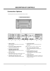
... ohm output) Connect to optional external speaker(s). * For further information, refer to the SVIDEO input. RS-232C INPUT (CONTROL/SERVICE) PORT Connect to the appropriate input port. 4. NOTE: AUDIO INPUT of S-VIDEO is indicated on the Monitor. 2. The voltage.../audio device to the remote control port on the Specifications page. REMOTE CONTROL Connect your monitor. Back Connection Panel REMOTE RS-232C INPUT CONTROL (CONTROL/SERVICE) DVI INPUT AUDIO INPUT RGB INPUT RGB OUTPUT 1 2 3 4 Y PB PR COMPONENT INPUT R L AUDIO INPUT S-VIDEO 5 6 R L (MONO) AUDIO INPUT VIDEO...
... ohm output) Connect to optional external speaker(s). * For further information, refer to the SVIDEO input. RS-232C INPUT (CONTROL/SERVICE) PORT Connect to the appropriate input port. 4. NOTE: AUDIO INPUT of S-VIDEO is indicated on the Monitor. 2. The voltage.../audio device to the remote control port on the Specifications page. REMOTE CONTROL Connect your monitor. Back Connection Panel REMOTE RS-232C INPUT CONTROL (CONTROL/SERVICE) DVI INPUT AUDIO INPUT RGB INPUT RGB OUTPUT 1 2 3 4 Y PB PR COMPONENT INPUT R L AUDIO INPUT S-VIDEO 5 6 R L (MONO) AUDIO INPUT VIDEO...
Service Manual
Page 11
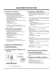
... data for the best condition of Equipment for Analog-RGB input is completed. 7. Method of heat-run mode by pressing power key on the Service Remote Control (S R/C) then allow to heat run at least 15 minutes. (2) Supply Window Pattern signal to DVI input using D, E key ... input the Y, Pb and Pr signal. (2) Press ADJ KEY on S R/C. O Manual adjustment is as below . ADJUSTMENT INSTRUCTIONS 6-4. Adjustment of 160 Gray Level(High Window Pattern), select Red Gain and Green Gain using A Key. 8. MU-42PM11: CB MU-42PM12X/MU-50PM10: DC 6) If Check Sum is not CB(or DC), repeat 3) ~ ...
... data for the best condition of Equipment for Analog-RGB input is completed. 7. Method of heat-run mode by pressing power key on the Service Remote Control (S R/C) then allow to heat run at least 15 minutes. (2) Supply Window Pattern signal to DVI input using D, E key ... input the Y, Pb and Pr signal. (2) Press ADJ KEY on S R/C. O Manual adjustment is as below . ADJUSTMENT INSTRUCTIONS 6-4. Adjustment of 160 Gray Level(High Window Pattern), select Red Gain and Green Gain using A Key. 8. MU-42PM11: CB MU-42PM12X/MU-50PM10: DC 6) If Check Sum is not CB(or DC), repeat 3) ~ ...


