Service Manual
Page 2
... Checking GSM Block 86 4.8 Checking Bluetooth Block 92 4.9 Power ON Troubleshooting 94 4.10 Charger Troubleshooting 96 4.11 USB Troubleshooting 99 4.12 SIM Detect Troubleshooting 100 4.13 Camera Troubleshooting 102 4.14 Keypad Backlight Troubleshooting ....105 4.15 Main LCD Troubleshooting 106 4.16 Receiver Path 107 4.17 Headset path 109 4.18 Speaker phone path 111 4.19 Main microphone 113 4.20 Headset microphone 115 4.21 Vibrator 117 5. DOWNLOAD 119 5.1 U250/KU250 DOWNLOAD 119 5.1.1 Introduction 119 5.1.2 Downloading Procedure 119 5.1.3 Troubleshooting Download Errors...
... Checking GSM Block 86 4.8 Checking Bluetooth Block 92 4.9 Power ON Troubleshooting 94 4.10 Charger Troubleshooting 96 4.11 USB Troubleshooting 99 4.12 SIM Detect Troubleshooting 100 4.13 Camera Troubleshooting 102 4.14 Keypad Backlight Troubleshooting ....105 4.15 Main LCD Troubleshooting 106 4.16 Receiver Path 107 4.17 Headset path 109 4.18 Speaker phone path 111 4.19 Main microphone 113 4.20 Headset microphone 115 4.21 Vibrator 117 5. DOWNLOAD 119 5.1 U250/KU250 DOWNLOAD 119 5.1.1 Introduction 119 5.1.2 Downloading Procedure 119 5.1.3 Troubleshooting Download Errors...
Service Manual
Page 4
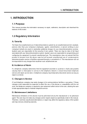
... make any charges that this model. 1.2 Regulatory Information A. C. INTRODUCTION 1. Incidence of Harm If a telephone company determines that unauthorized alternations or repair may affect the regulatory status of own system. System users are responsible for your telecommunications system. Changes in substantial additional charges for the security of the system and may temporarily disconnect service as long as specifically noted in this manual...
... make any charges that this model. 1.2 Regulatory Information A. C. INTRODUCTION 1. Incidence of Harm If a telephone company determines that unauthorized alternations or repair may affect the regulatory status of own system. System users are responsible for your telecommunications system. Changes in substantial additional charges for the security of the system and may temporarily disconnect service as long as specifically noted in this manual...
Service Manual
Page 5
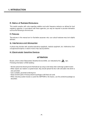
... the end user. Pictures The pictures in these protective packages until these agencies, you may cause problems. H. Interference from unsuppressed engines or electric motors may be required to provide information such as defined by using a wrist strap when exchange system boards. • When repairs are used. • When returning system boards or parts like EEPROM to the factory, use the...
... the end user. Pictures The pictures in these protective packages until these agencies, you may cause problems. H. Interference from unsuppressed engines or electric motors may be required to provide information such as defined by using a wrist strap when exchange system boards. • When repairs are used. • When returning system boards or parts like EEPROM to the factory, use the...
Service Manual
Page 16
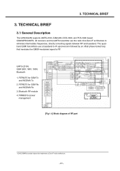
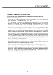
... part 1 QUALCOMM's branded chipset that translates the GMSK-modulated signal to eliminate intermediate frequencies, directly converting signals between RF and baseband. The quadband GSM transmitters use the radio One1Zero-IF architecture to RF. 3. TECHNICAL BRIEF 3.1 General Description The U250/KU250 supports UMTS-2100, GSM-900, DCS-1800, and PCS-1900 based GSM/GPRS/UMTS. Bluetooth RF module 4. All receivers...
... part 1 QUALCOMM's branded chipset that translates the GMSK-modulated signal to eliminate intermediate frequencies, directly converting signals between RF and baseband. The quadband GSM transmitters use the radio One1Zero-IF architecture to RF. 3. TECHNICAL BRIEF 3.1 General Description The U250/KU250 supports UMTS-2100, GSM-900, DCS-1800, and PCS-1900 based GSM/GPRS/UMTS. Bluetooth RF module 4. All receivers...
Service Manual
Page 17
... supply voltages using radioOne ZIF technique. TECHNICAL BRIEF A generic, high-level functional block diagram of U250/KU250 is applied to the ramping control pin of up -converter translates the GMSK-modulated signal to improve efficiency. 1. The RFIC Rx analog baseband outputs, for further signal processing. This versatile device integrates all wireless handset power management, general housekeeping, and user interface support functions...
... supply voltages using radioOne ZIF technique. TECHNICAL BRIEF A generic, high-level functional block diagram of U250/KU250 is applied to the ramping control pin of up -converter translates the GMSK-modulated signal to improve efficiency. 1. The RFIC Rx analog baseband outputs, for further signal processing. This versatile device integrates all wireless handset power management, general housekeeping, and user interface support functions...
Service Manual
Page 26
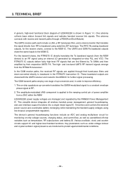
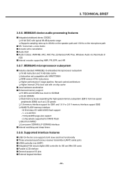
... for power savings - Charger transistor protection by power limit control - Control drivers for tracking time and generating associated alarms - Low power mode available on -chip RC assures MSM device sleep clock - Adjusted multiplexer output is optional - 3. TECHNICAL BRIEF 3.5.4 PMIC Functional Block Diagram (U300 : PM6650-2M) • Input power management - Valid external supply attachment and removal detection - Trickle, constant current, constant voltage, and pulsed charging...
... for power savings - Charger transistor protection by power limit control - Control drivers for tracking time and generating associated alarms - Low power mode available on -chip RC assures MSM device sleep clock - Adjusted multiplexer output is optional - 3. TECHNICAL BRIEF 3.5.4 PMIC Functional Block Diagram (U300 : PM6650-2M) • Input power management - Valid external supply attachment and removal detection - Trickle, constant current, constant voltage, and pulsed charging...
Service Manual
Page 27
... a USB peripheral, or connecting the MSM device to 3.1V in a small package - 84-pin BCCS with volume controlled 500 mW) • IC-level interfaces - Vibration motor driver programmable from 1.2 to other peripherals RUIM level translators enable MSM device interfacing with external modules • Twelve multi-purpose pins that can be configured as keypad backlight, LCD backlight, camera flash, and general-purpose drivers - Supports the MSM device...
... a USB peripheral, or connecting the MSM device to 3.1V in a small package - 84-pin BCCS with volume controlled 500 mW) • IC-level interfaces - Vibration motor driver programmable from 1.2 to other peripherals RUIM level translators enable MSM device interfacing with external modules • Twelve multi-purpose pins that can be configured as keypad backlight, LCD backlight, camera flash, and general-purpose drivers - Supports the MSM device...
Service Manual
Page 30
... are specified over a number of -band noise levels and Rx-band losses between the two. TECHNICAL BRIEF 3.5.6 UMTS Duplexer(FL104:ACMD-7602) A UMTS duplexer splits a single operating band into the Rx band. Important performance requirements include; • Insertion loss. this fairly narrowband device is also in -band to desensitize the receiver. The required Tx...
... are specified over a number of -band noise levels and Rx-band losses between the two. TECHNICAL BRIEF 3.5.6 UMTS Duplexer(FL104:ACMD-7602) A UMTS duplexer splits a single operating band into the Rx band. Important performance requirements include; • Insertion loss. this fairly narrowband device is also in -band to desensitize the receiver. The required Tx...
Service Manual
Page 33
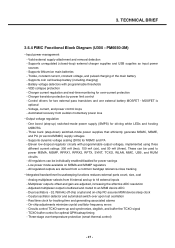
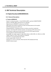
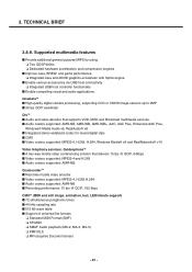
TECHNICAL BRIEF 3. Features(MSM6245) • Support for Open Mobile Alliance (OMA) DRM v2.0, SIM-lock and IMEI integrity. tri-band WCDMA (UMTS), quad-band GSM/GPRS/EDGE • Support for WCDMA (UMTS) uplink data rate up to 384 kbps • ...Bluetooth 1.2 baseband processor for wireless connectivity to peripherals • Qcamera™ with 30 fps QCIF viewfinder resolution, and support for 2 MP camera sensors • Direct interface to digital camera module with portable music players • Vocoder support (AMR, FR, EFR, HR) • Advanced 14 x 14 mm, 0.5 mm pitch, 409-pin lead-free...
TECHNICAL BRIEF 3. Features(MSM6245) • Support for Open Mobile Alliance (OMA) DRM v2.0, SIM-lock and IMEI integrity. tri-band WCDMA (UMTS), quad-band GSM/GPRS/EDGE • Support for WCDMA (UMTS) uplink data rate up to 384 kbps • ...Bluetooth 1.2 baseband processor for wireless connectivity to peripherals • Qcamera™ with 30 fps QCIF viewfinder resolution, and support for 2 MP camera sensors • Direct interface to digital camera module with portable music players • Vocoder support (AMR, FR, EFR, HR) • Advanced 14 x 14 mm, 0.5 mm pitch, 409-pin lead-free...
Service Manual
Page 37
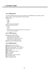
...; 1 phase/2 phase access procedures ■ Link adaptation and IR ■ NACC, extended UL TBF. - 38 - EDGE features ■ EDGE E2 power class for CS data and fax ❏ No sub-rates are supported by the MSM6245 device hardware. GPRS features ■ Packet switched data (GPRS) ❏ DTM (Simple Class A) operation ❏ Multi-slot class 12 data services ❏ CS...
...; 1 phase/2 phase access procedures ■ Link adaptation and IR ■ NACC, extended UL TBF. - 38 - EDGE features ■ EDGE E2 power class for CS data and fax ❏ No sub-rates are supported by the MSM6245 device hardware. GPRS features ■ Packet switched data (GPRS) ❏ DTM (Simple Class A) operation ❏ Multi-slot class 12 data services ❏ CS...
Service Manual
Page 38
... bus clock for EBI1 and 1.8 V or 2.6 V memory interface support EBI2 ❏ NAND FLASH memory interface - 8/16-bit data I /O pins ■ External keypad interface - 39 - Voice mail + voice memo ■ Acoustic echo cancellation ■ Audio AGC ■ Audio Codecs: AMR-NB, AAC, AAC Plus, Enhanced AAC Plus, Windows Audio v9, Real Audio 8 (G2) ■ Internal vocoder supporting AMR, FR, EFR, and HR 3.8.7. 3. MSM6245 device audio...
... bus clock for EBI1 and 1.8 V or 2.6 V memory interface support EBI2 ❏ NAND FLASH memory interface - 8/16-bit data I /O pins ■ External keypad interface - 39 - Voice mail + voice memo ■ Acoustic echo cancellation ■ Audio AGC ■ Audio Codecs: AMR-NB, AAC, AAC Plus, Enhanced AAC Plus, Windows Audio v9, Real Audio 8 (G2) ■ Internal vocoder supporting AMR, FR, EFR, and HR 3.8.7. 3. MSM6245 device audio...
Service Manual
Page 39
... supported: AMR-NB. QcamcorderTM ■ Real time mobile video encoder ■ Video codecs supported: MPEG-4, H.263.H.264 ■ Audio codecs supported: AMR-NB ■ Recording performance: 15 fps @ QCIF, 192 kbps CMXTM (MIDI and still image, animation, text, LED/vibrate support) ■ 72 simultaneous polyphonic tones ■ 44 kHz sampling rate ■ 512 kB wave table ■ Support of universal file formats ❏ Standard MIDI Format...
... supported: AMR-NB. QcamcorderTM ■ Real time mobile video encoder ■ Video codecs supported: MPEG-4, H.263.H.264 ■ Audio codecs supported: AMR-NB ■ Recording performance: 15 fps @ QCIF, 192 kbps CMXTM (MIDI and still image, animation, text, LED/vibrate support) ■ 72 simultaneous polyphonic tones ■ 44 kHz sampling rate ■ 512 kB wave table ■ Support of universal file formats ❏ Standard MIDI Format...
Service Manual
Page 42
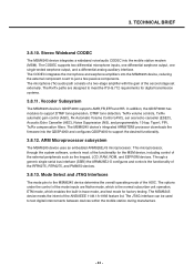
..., ETM mode, which enables the built-in trace mode, and test mode for digital transmission systems. 3.8.11. The MSM6245 device's integrated ARM9TDMI processor downloads the firmware into the QDSP4000 and configures QDSP4000 to test digital interconnects between devices within the mobile station during manufacture. - 43 - Mode Select and JTAG Interfaces The mode pins to support DTMF tone generation, DTMF tone detection, Tx/Rx volume controls, Tx...
..., ETM mode, which enables the built-in trace mode, and test mode for digital transmission systems. 3.8.11. The MSM6245 device's integrated ARM9TDMI processor downloads the firmware into the QDSP4000 and configures QDSP4000 to test digital interconnects between devices within the mobile station during manufacture. - 43 - Mode Select and JTAG Interfaces The mode pins to support DTMF tone generation, DTMF tone detection, Tx/Rx volume controls, Tx...
Service Manual
Page 58
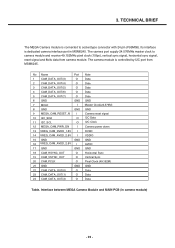
... CAM_DATA_OUT(0) O 23 CAM_DATA_OUT(1) O 24 CAM_DATA_OUT(2) O Note Data Data Data Data Data GND Master Clock(24.576M) GND Camera reset signal I2C Data I2C Clock Camera power down DVDD VDDIO GND AVDD GND Horizontal Sync Vertical Sync Pixel Clock (49.152M) GND Data Data Data Table. The camera module is controlled by I2C port from camera module. Its interface is connected to camera module and receive 49.152MHz pixel clock (15fps), vertical sync signal, horizontal sync signal, reset signal and 8bits data from MSM6245. 3.
... CAM_DATA_OUT(0) O 23 CAM_DATA_OUT(1) O 24 CAM_DATA_OUT(2) O Note Data Data Data Data Data GND Master Clock(24.576M) GND Camera reset signal I2C Data I2C Clock Camera power down DVDD VDDIO GND AVDD GND Horizontal Sync Vertical Sync Pixel Clock (49.152M) GND Data Data Data Table. The camera module is controlled by I2C port from camera module. Its interface is connected to camera module and receive 49.152MHz pixel clock (15fps), vertical sync signal, horizontal sync signal, reset signal and 8bits data from MSM6245. 3.
Service Manual
Page 59
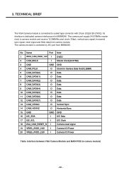
The camera module is connected to camera module and receive 12.288MHz pixel clock (15fps), vertical sync signal, horizontal sync signal, reset signal and 8bits data from MSM6245. TECHNICAL BRIEF The VGA Camera module is controlled by I2C port from camera module. The camera port supply 24.576MHz master clock to socket type connector with 20 pin (CLE9120-2761E). Interface between VGA Camera Module and MAIN PCB (in MSM6245. 3. No Name...
The camera module is connected to camera module and receive 12.288MHz pixel clock (15fps), vertical sync signal, horizontal sync signal, reset signal and 8bits data from MSM6245. TECHNICAL BRIEF The VGA Camera module is controlled by I2C port from camera module. The camera port supply 24.576MHz master clock to socket type connector with 20 pin (CLE9120-2761E). Interface between VGA Camera Module and MAIN PCB (in MSM6245. 3. No Name...

Service Manual
Page 61
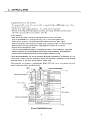
The NM176CN1 model is divided into Red, Green and Blue sub-pixels and dots which are arranged in MSM6245. CN400 35 34 33 32 31 30 29 28 ... has a 1.76 inch diagonally measured active display area with 35 pin (XF2B-3545-31A / OMROM) The LCD module is connected to LCD KEY FPCB with 176(RGB)X220 resolution. TECHNICAL BRIEF 3.11.7. LCD Driver IC: NT3916 (NOVATEK). - 16 bit CPU interface Parallel 3.11.8. Display mode(Main LCD) : Normally White, Transmissive TN mode 265K colors. - Display & LCD FPC Interface LCD module...
The NM176CN1 model is divided into Red, Green and Blue sub-pixels and dots which are arranged in MSM6245. CN400 35 34 33 32 31 30 29 28 ... has a 1.76 inch diagonally measured active display area with 35 pin (XF2B-3545-31A / OMROM) The LCD module is connected to LCD KEY FPCB with 176(RGB)X220 resolution. TECHNICAL BRIEF 3.11.7. LCD Driver IC: NT3916 (NOVATEK). - 16 bit CPU interface Parallel 3.11.8. Display mode(Main LCD) : Normally White, Transmissive TN mode 265K colors. - Display & LCD FPC Interface LCD module...
Service Manual
Page 96
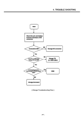
4. END NO Change the board [ Charger Troubleshooting Flow ] - 97 - TROUBLE SHOOTING Start Check the pin and battery Connect terminals of I /O connector Yes Is the TA (or USB Cable) voltage 5.1V (or 5.0V)? NO Change I /O connector Connection OK? Yes NO Change TA (or USB Cable) Is it charging properly Yes After turning on Q301(or Q302) , Q302?
4. END NO Change the board [ Charger Troubleshooting Flow ] - 97 - TROUBLE SHOOTING Start Check the pin and battery Connect terminals of I /O connector Yes Is the TA (or USB Cable) voltage 5.1V (or 5.0V)? NO Change I /O connector Connection OK? Yes NO Change TA (or USB Cable) Is it charging properly Yes After turning on Q301(or Q302) , Q302?

Service Manual
Page 116
Start Operate the Vibrator Work well? Yes NO Change vibrator or PM6650 End TP400 TP401 L400 56nH D400 RB521S-30 +VPWR MOTOR_PWR- - 117 - 4. TROUBLE SHOOTING 4.21 Vibrator The Vibrator is reference to +VPWR. The Vibrator motor driver is an SBI-programmable voltage out that is connected between +VPWR and VIB_DRV_N (PM6650 25 pin).
Start Operate the Vibrator Work well? Yes NO Change vibrator or PM6650 End TP400 TP401 L400 56nH D400 RB521S-30 +VPWR MOTOR_PWR- - 117 - 4. TROUBLE SHOOTING 4.21 Vibrator The Vibrator is reference to +VPWR. The Vibrator motor driver is an SBI-programmable voltage out that is connected between +VPWR and VIB_DRV_N (PM6650 25 pin).
Service Manual
Page 118
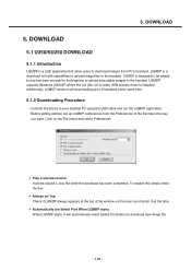
... simply check the box. ➢ Always on the File menu and select Preferences. ➢ Play a success sound It will automatically select Select Port button to 9 handsets at the top of the file menu the way you want. Before getting started, set up to download new image file. - 119 - LGMDP supports Windows 2000/XP where the LG (Ver 4.6 or later) USB modem driver is designed to handset. 5. LGMDP is installed...
... simply check the box. ➢ Always on the File menu and select Preferences. ➢ Play a success sound It will automatically select Select Port button to 9 handsets at the top of the file menu the way you want. Before getting started, set up to download new image file. - 119 - LGMDP supports Windows 2000/XP where the LG (Ver 4.6 or later) USB modem driver is designed to handset. 5. LGMDP is installed...
Service Manual
Page 120
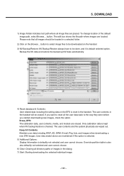
... should be located in a selected folder. 2) Click on the handset. 3) NV Backup/Restore: NV Backup/Restore always have to be erased. If you started downloading new images, check the option. Override partition table is checked. Keep All Contents Maintain user data including WAP, AD, DRM, E-mail, Play lists, and images when downloading a new S/W images. Erase_EFS: The calibration data, user contents, media, and module are wiped out. The edit box shows the file path...
... should be located in a selected folder. 2) Click on the handset. 3) NV Backup/Restore: NV Backup/Restore always have to be erased. If you started downloading new images, check the option. Override partition table is checked. Keep All Contents Maintain user data including WAP, AD, DRM, E-mail, Play lists, and images when downloading a new S/W images. Erase_EFS: The calibration data, user contents, media, and module are wiped out. The edit box shows the file path...


