
Owner's Manual (English)
Page 1
... Agency(EPA). www.lgusa.com / www.lg.ca See the label attached on the back cover and quote this product meets the ENERGY STAR guidelines for future reference. Record model number and serial number of the set of power-saving guidelines issued by the ... for energy efficiency. As an ENERGY STAR Partner LGE U.S.A., Inc. has determined that this information to your set. LCD TV PLASMA TV OWNER'S MANUAL LCD TV MODELS PLASMA TV MODELS 32LB9D 32LB9DB 47LC7DF 50PY3D 50PY3DF 60PY3D 60PY3DF Please read this manual carefully before operating your dealer when you require service.
... Agency(EPA). www.lgusa.com / www.lg.ca See the label attached on the back cover and quote this product meets the ENERGY STAR guidelines for future reference. Record model number and serial number of the set of power-saving guidelines issued by the ... for energy efficiency. As an ENERGY STAR Partner LGE U.S.A., Inc. has determined that this information to your set. LCD TV PLASMA TV OWNER'S MANUAL LCD TV MODELS PLASMA TV MODELS 32LB9D 32LB9DB 47LC7DF 50PY3D 50PY3DF 60PY3D 60PY3DF Please read this manual carefully before operating your dealer when you require service.
Owner's Manual (English)
Page 6
...60 XD - Digital Broadcasting System Captions . . .79 - Picture Mode - Black( Darkness) Level 63 Picture Reset 64 Image Sticking Minimization( ISM) Method 65 Low-Power Picture Mode 66 Front Ddisplay 67 SOUND & LANGUAGE CONTROL Auto Volume Leveler ( Auto Volume 68 Preset Sound Settings( Sound Mode 69 Sound Setting...39 Volume Adjustment 40 On-Screen Menus Selection 41 Channel Setup - User Mode 70 Balance 72 Stereo / SAP Broadcast Setup 73 TV Speakers On/ Off Setup 74 Audio Language 75 On-Screen Menus Language Selection 76 Caption Mode - Preset 58 Manual Picture Adjustment ...
...60 XD - Digital Broadcasting System Captions . . .79 - Picture Mode - Black( Darkness) Level 63 Picture Reset 64 Image Sticking Minimization( ISM) Method 65 Low-Power Picture Mode 66 Front Ddisplay 67 SOUND & LANGUAGE CONTROL Auto Volume Leveler ( Auto Volume 68 Preset Sound Settings( Sound Mode 69 Sound Setting...39 Volume Adjustment 40 On-Screen Menus Selection 41 Channel Setup - User Mode 70 Balance 72 Stereo / SAP Broadcast Setup 73 TV Speakers On/ Off Setup 74 Audio Language 75 On-Screen Menus Language Selection 76 Caption Mode - Preset 58 Manual Picture Adjustment ...

Owner's Manual (English)
Page 7
Manual Clock Setup 82 Auto On/ Off Time Setting 83 Sleep Time Setting 84 Auto Shut-off Setting 85 PARENTAL CONTROL / RATINGS Set Password & Lock System 86 Channel Blocking 88 Movie & TV Rating 89 Downloadable Rating 89 External Input Blocking 92 Key Lock 92 APPENDIX Troubleshooting 93 Maintenance 95 Product Specifications 96 Programming the Remote Control 97 IR Codes 101 External Control through RS-232C 103 5 Auto Clock Setup 81 - TIME SETTING Clock Setting -
Manual Clock Setup 82 Auto On/ Off Time Setting 83 Sleep Time Setting 84 Auto Shut-off Setting 85 PARENTAL CONTROL / RATINGS Set Password & Lock System 86 Channel Blocking 88 Movie & TV Rating 89 Downloadable Rating 89 External Input Blocking 92 Key Lock 92 APPENDIX Troubleshooting 93 Maintenance 95 Product Specifications 96 Programming the Remote Control 97 IR Codes 101 External Control through RS-232C 103 5 Auto Clock Setup 81 - TIME SETTING Clock Setting -

Owner's Manual (English)
Page 10
I Here shown may be somewhat different from your TV. Touch Pad ENTER INPUT Button POWER Button ENTER Button VOLUME MENU Button (F,G) Buttons CHANNEL (E,D) Buttons 8 PREPARATION FRONT PANEL CONTROLS I If your product has a protection tape attached, remove the tape. And then wipe the product with your product, use it). 50/60 inches PREPARATION Remote Control Sensor Program Display . . Power Standby Indicator • illuminates red in standby mode. • illuminates white when the set is included with a cloth (If a polishing cloth is switched on.
I Here shown may be somewhat different from your TV. Touch Pad ENTER INPUT Button POWER Button ENTER Button VOLUME MENU Button (F,G) Buttons CHANNEL (E,D) Buttons 8 PREPARATION FRONT PANEL CONTROLS I If your product has a protection tape attached, remove the tape. And then wipe the product with your product, use it). 50/60 inches PREPARATION Remote Control Sensor Program Display . . Power Standby Indicator • illuminates red in standby mode. • illuminates white when the set is included with a cloth (If a polishing cloth is switched on.

Owner's Manual (English)
Page 11
... conditions. POWER Button Remote Control Power/Standby Indicator Sensor • illuminates red in standby mode. • illuminates green when the set is switched on . 9 Power/Standby Indicator Remote Control Sensor • illuminates red in standby mode. • illuminates green when the... set is switched on . 32LB9D* CH CH CHANNEL (E,D) ButtonsCH VOL VOLUME (F,G) Buttons VOL ENTER Button MENU Button VOL ENTER MENU INPUT /I...
... conditions. POWER Button Remote Control Power/Standby Indicator Sensor • illuminates red in standby mode. • illuminates green when the set is switched on . 9 Power/Standby Indicator Remote Control Sensor • illuminates red in standby mode. • illuminates green when the... set is switched on . 32LB9D* CH CH CHANNEL (E,D) ButtonsCH VOL VOLUME (F,G) Buttons VOL ENTER Button MENU Button VOL ENTER MENU INPUT /I...

Owner's Manual (English)
Page 14
Caution: Please make sure that is mounted on or hang from your TV. 50 inches 60 inches 47LC7DF 32LB9D* PREPARATION I Insert the TV brackets and bolts(or eye-bolts) to tighten the product to a wall so it becomes horizontal between the wall and the product. Match the height... A WALL I This feature is safer to tie the product. I Here shown may cause injury/death. 12 Stand Desk Additionally, we recommend that you set up the TV close to the wall as shown in the picture. *Insert the eye-bolts and tighten them securely in the product. I Use a sturdy rope (not ...
Caution: Please make sure that is mounted on or hang from your TV. 50 inches 60 inches 47LC7DF 32LB9D* PREPARATION I Insert the TV brackets and bolts(or eye-bolts) to tighten the product to a wall so it becomes horizontal between the wall and the product. Match the height... A WALL I This feature is safer to tie the product. I Here shown may cause injury/death. 12 Stand Desk Additionally, we recommend that you set up the TV close to the wall as shown in the picture. *Insert the eye-bolts and tighten them securely in the product. I Use a sturdy rope (not ...
Owner's Manual (English)
Page 20
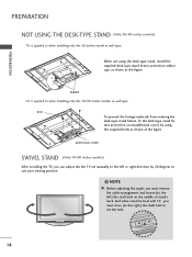
... as wall-type. PREPARATION PREPARATION NOT USING THE DESK-TYPE STAND (Only 50/60 inches models) I It is applied to suit your viewing position. NOTE G Before adjusting the angle, you can adjust the the TV set the hole. 18 BOLT To prevent the foreign materials from entering the desk-type... stand fixture, fix the desk-type stand fixture protection cover(additional cover) by 20 degrees to when installing only the 60 inches model as wall-type.
... as wall-type. PREPARATION PREPARATION NOT USING THE DESK-TYPE STAND (Only 50/60 inches models) I It is applied to suit your viewing position. NOTE G Before adjusting the angle, you can adjust the the TV set the hole. 18 BOLT To prevent the foreign materials from entering the desk-type... stand fixture, fix the desk-type stand fixture protection cover(additional cover) by 20 degrees to when installing only the 60 inches model as wall-type.
Owner's Manual (English)
Page 22
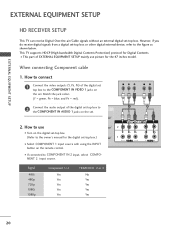
... if you do receive digital signals from a digital set . I This part of the digital set top box to the COMPONENT IN VIDEO 1 jacks on the set -top box. EXTERNAL EQUIPMENT SETUP EXTERNAL EQUIPMENT SETUP HD RECEIVER SETUP This TV can receive Digital Over-the-air/Cable signals without ...an external digital set . Y PB PR L R 1 2 2. Signal 480i 480p 720p 1080i 1080p Component 1/2 Yes Yes ...
... if you do receive digital signals from a digital set . I This part of the digital set top box to the COMPONENT IN VIDEO 1 jacks on the set -top box. EXTERNAL EQUIPMENT SETUP EXTERNAL EQUIPMENT SETUP HD RECEIVER SETUP This TV can receive Digital Over-the-air/Cable signals without ...an external digital set . Y PB PR L R 1 2 2. Signal 480i 480p 720p 1080i 1080p Component 1/2 Yes Yes ...
Owner's Manual (English)
Page 23
... with using the INPUT button on the digital set-top box. (Refer to the owner's manual for the digital set . How to connect 1 Connect the RGB output of the digital set-top box to the RGB (PC) jack on the set. 2 Connect the audio outputs of the set-top box to HDMI/DVI IN1, 2 or... 3 jack on the set . 2 No separated audio connection is necessary. 2. RGB...
... with using the INPUT button on the digital set-top box. (Refer to the owner's manual for the digital set . How to connect 1 Connect the RGB output of the digital set-top box to the RGB (PC) jack on the set. 2 Connect the audio outputs of the set-top box to HDMI/DVI IN1, 2 or... 3 jack on the set . 2 No separated audio connection is necessary. 2. RGB...
Owner's Manual (English)
Page 24
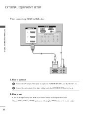
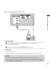
How to use I Turn on the digital set-top box. (Refer to the owner's manual for the digital set-top box.) I Select HDMI1, HDMI2 or HDMI3 input source with using the INPUT button on the set -top box to the AUDIO(RGB/DVI) jack on the remote control. 22 How to connect 1 Connect the DVI output of the digital set . 2. EXTERNAL EQUIPMENT SETUP When connecting HDMI to the HDMI/DVI IN1, 2 or 3 jack on the set. 2 Connect the audio output of the digital set-top box to DVI cable RGB 3 EXTERNAL EQUIPMENT SETUP 2 1 DVI-DTV OUTPUT L R 1.
How to use I Turn on the digital set-top box. (Refer to the owner's manual for the digital set-top box.) I Select HDMI1, HDMI2 or HDMI3 input source with using the INPUT button on the set -top box to the AUDIO(RGB/DVI) jack on the remote control. 22 How to connect 1 Connect the DVI output of the digital set . 2. EXTERNAL EQUIPMENT SETUP When connecting HDMI to the HDMI/DVI IN1, 2 or 3 jack on the set. 2 Connect the audio output of the digital set-top box to DVI cable RGB 3 EXTERNAL EQUIPMENT SETUP 2 1 DVI-DTV OUTPUT L R 1.
Owner's Manual (English)
Page 25
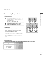
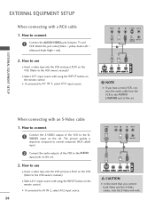
...1 Connect the video outputs (Y, PB, PR) of the DVD to the COMPONENT IN VIDEO1 jacks on the set . Match the jack colors (Y = green, PB = blue, and PR = red). 2 Connect the ...audio outputs of the DVD to the COMPONENT IN AUDIO1 jacks on the set . 2. Y PB PR L R 1 2 Component Input ports To get better picture quality, connect a DVD player to the...I Refer to the component input ports as shown below. Component ports on the TV Y PB PR Video output ports on the DVD player, insert a DVD. EXTERNAL EQUIPMENT SETUP DVD SETUP When connecting ...
...1 Connect the video outputs (Y, PB, PR) of the DVD to the COMPONENT IN VIDEO1 jacks on the set . Match the jack colors (Y = green, PB = blue, and PR = red). 2 Connect the ...audio outputs of the DVD to the COMPONENT IN AUDIO1 jacks on the set . 2. Y PB PR L R 1 2 Component Input ports To get better picture quality, connect a DVD player to the...I Refer to the component input ports as shown below. Component ports on the TV Y PB PR Video output ports on the DVD player, insert a DVD. EXTERNAL EQUIPMENT SETUP DVD SETUP When connecting ...
Owner's Manual (English)
Page 26
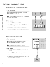
How to connect 1 Connect the S-VIDEO output of the DVD to the S-VIDEO input on the set. 2 Connect the audio outputs of the DVD to the HDMI/DVI IN1, 2 or 3 jack on the set . 2. I If the DVD does not support Auto HDMI, you need to the DVD player's manual for... operating instructions. I Refer to set the output resolution appropriately. 24 1 HDMI-DVD OUTPUT How to the AUDIO input jacks on the set . 2 No separated audio connection is necessary. 2. S-VIDEO AUDIO L R 1 2 EXTERNAL EQUIPMENT SETUP When connecting ...
How to connect 1 Connect the S-VIDEO output of the DVD to the S-VIDEO input on the set. 2 Connect the audio outputs of the DVD to the HDMI/DVI IN1, 2 or 3 jack on the set . 2. I If the DVD does not support Auto HDMI, you need to the DVD player's manual for... operating instructions. I Refer to set the output resolution appropriately. 24 1 HDMI-DVD OUTPUT How to the AUDIO input jacks on the set . 2 No separated audio connection is necessary. 2. S-VIDEO AUDIO L R 1 2 EXTERNAL EQUIPMENT SETUP When connecting ...
Owner's Manual (English)
Page 27
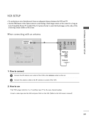
...remain visible on the VCR. (Refer to the same channel number. If the 4:3 picture format is used; How to use I Set VCR output switch to 3 or 4 and then tune TV to the VCR owner's manual.) 25 EXTERNAL EQUIPMENT SETUP VCR SETUP I To avoid picture noise (interference), leave an adequate distance ... to connect 1 Connect the RF antenna out socket of the VCR to the Antenna socket on the set. 2 Connect the antenna cable to avoid having a fixed image remain on the sides of time(Only Plasma TV model). When connecting with an antenna ANTENNA/ CABLE IN 1 ANT OUT S-VIDEO VIDEO L R ANT IN ...
...remain visible on the VCR. (Refer to the same channel number. If the 4:3 picture format is used; How to use I Set VCR output switch to 3 or 4 and then tune TV to the VCR owner's manual.) 25 EXTERNAL EQUIPMENT SETUP VCR SETUP I To avoid picture noise (interference), leave an adequate distance ... to connect 1 Connect the RF antenna out socket of the VCR to the Antenna socket on the set. 2 Connect the antenna cable to avoid having a fixed image remain on the sides of time(Only Plasma TV model). When connecting with an antenna ANTENNA/ CABLE IN 1 ANT OUT S-VIDEO VIDEO L R ANT IN ...
Owner's Manual (English)
Page 28
...1 Connect the S-VIDEO output of the VCR to connect 1 Connect the AUDIO/VIDEO jacks between TV and VCR. How to the S V I If connected to the AUDIO input jacks on the set. I D E O input on the set . compared to normal composite (RCA cable) input. 2 Connect the audio outputs of the... set . 2. How to use I Select A V 1 input source with using the INPUT button on the VCR....
...1 Connect the S-VIDEO output of the VCR to connect 1 Connect the AUDIO/VIDEO jacks between TV and VCR. How to the S V I If connected to the AUDIO input jacks on the set. I D E O input on the set . compared to normal composite (RCA cable) input. 2 Connect the audio outputs of the... set . 2. How to use I Select A V 1 input source with using the INPUT button on the VCR....

Owner's Manual (English)
Page 29
I If connected to use I Operate the corresponding external equipment. 27 I Select AV2 input source with using the INPUT button on the remote control. How to AV IN 1 input, select AV1 input source. Match the jack colors. (Video = yellow, Audio Left = white, and Audio Right = red) 2. How to connect 1 Connect the AUDIO/VIDEO jacks between TV and external equipment. EXTERNAL EQUIPMENT SETUP OTHER A/V SOURCE SETUP USB IN VIDEO L/MONO AUDIO R S-VIDEO 1 AV IN 2 VIDEO L R Camcorder Video Game Set 1.
I If connected to use I Operate the corresponding external equipment. 27 I Select AV2 input source with using the INPUT button on the remote control. How to AV IN 1 input, select AV1 input source. Match the jack colors. (Video = yellow, Audio Left = white, and Audio Right = red) 2. How to connect 1 Connect the AUDIO/VIDEO jacks between TV and external equipment. EXTERNAL EQUIPMENT SETUP OTHER A/V SOURCE SETUP USB IN VIDEO L/MONO AUDIO R S-VIDEO 1 AV IN 2 VIDEO L R Camcorder Video Game Set 1.

Owner's Manual (English)
Page 30
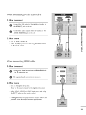
I Turn on the PC and the set . 2. How to the TV's settings. RGB 1 2 NOTE G Check the image on the remote control. There may be changed, change the refresh rate to the AUDIO (RGB/DVI) jack on the ... another rate or adjust the brightness and contrast on the set . When connecting D-sub 15 pin cable 1. How to connect 1 Connect the RGB output of the PC graphic card. RGB OUTPUT AUDIO 28 EXTERNAL EQUIPMENT SETUP EXTERNAL EQUIPMENT SETUP PC SETUP This TV provides Plug and Play capability, meaning that the PC...
I Turn on the PC and the set . 2. How to the TV's settings. RGB 1 2 NOTE G Check the image on the remote control. There may be changed, change the refresh rate to the AUDIO (RGB/DVI) jack on the ... another rate or adjust the brightness and contrast on the set . When connecting D-sub 15 pin cable 1. How to connect 1 Connect the RGB output of the PC graphic card. RGB OUTPUT AUDIO 28 EXTERNAL EQUIPMENT SETUP EXTERNAL EQUIPMENT SETUP PC SETUP This TV provides Plug and Play capability, meaning that the PC...
Owner's Manual (English)
Page 31
... to connect DVI-PC OUTPUT AUDIO 1 Connect the DVI output of PC graphics card's output resolution to set . (Use the HDMI to DVI cable) 2 Connect the PC audio output to DVI cable RGB EXTERNAL EQUIPMENT SETUP 1 2 1. To get the best picture quality, adjust ...the output resolution of the PC to the HDMI/DVI IN1, 2 or 3 jack on the set the output resolution appropriately. G If the PC does not support Auto DVI, you need to 1920x1080, 60Hz. (32LB9D* model: 1360x768, 60Hz) 29 NOTE G If the...
... to connect DVI-PC OUTPUT AUDIO 1 Connect the DVI output of PC graphics card's output resolution to set . (Use the HDMI to DVI cable) 2 Connect the PC audio output to DVI cable RGB EXTERNAL EQUIPMENT SETUP 1 2 1. To get the best picture quality, adjust ...the output resolution of the PC to the HDMI/DVI IN1, 2 or 3 jack on the set the output resolution appropriately. G If the PC does not support Auto DVI, you need to 1920x1080, 60Hz. (32LB9D* model: 1360x768, 60Hz) 29 NOTE G If the...

Owner's Manual (English)
Page 34
... G button to enter the screen adjustment menu. EXTERNAL EQUIPMENT SETUP EXTERNAL EQUIPMENT SETUP Screen Setup for PC mode Overview When the RGB input, of the set is connected to the screen adjustment menu. 32 When you to a PC Output, Select RGB-PC with using the INPUT button on the remote control...
... G button to enter the screen adjustment menu. EXTERNAL EQUIPMENT SETUP EXTERNAL EQUIPMENT SETUP Screen Setup for PC mode Overview When the RGB input, of the set is connected to the screen adjustment menu. 32 When you to a PC Output, Select RGB-PC with using the INPUT button on the remote control...

Owner's Manual (English)
Page 35
... Prev Resolution XGA(1024, 1280, 1360) isn't distinguished because of characters. And the horizontal screen size will also change. Resolution Position Size Phase Reset G Initialize Settings. EXTERNAL EQUIPMENT SETUP Adjustment for screen Resolution, Position, Size, Phase, Reset 1 Use D or E button to select Resolution, Position, Size, or Phase. 2 Press the ENTER button...
... Prev Resolution XGA(1024, 1280, 1360) isn't distinguished because of characters. And the horizontal screen size will also change. Resolution Position Size Phase Reset G Initialize Settings. EXTERNAL EQUIPMENT SETUP Adjustment for screen Resolution, Position, Size, Phase, Reset 1 Use D or E button to select Resolution, Position, Size, or Phase. 2 Press the ENTER button...

Owner's Manual (English)
Page 37
... Copy Protection) function. 1 2 35 EXTERNAL EQUIPMENT SETUP AUDIO OUT SETUP Send the TV's audio to the TV's AUDIO OUT jacks 1 2 Set the "TV Speaker option - Digital 1 Connect one end of the optical or coaxial cable to the TV's OPTICAL or COAXIAL port of DIGITAL AUDIO OUT. 2 Connect the other end of... the optical or coaxial cable to the digital audio input on the audio equipment. 3 Set the "TV Speaker option - G Block the SPDIF out(optical/coaxial) about the contents with external audio equipment, such as amplifers or speakers, please turn ...
... Copy Protection) function. 1 2 35 EXTERNAL EQUIPMENT SETUP AUDIO OUT SETUP Send the TV's audio to the TV's AUDIO OUT jacks 1 2 Set the "TV Speaker option - Digital 1 Connect one end of the optical or coaxial cable to the TV's OPTICAL or COAXIAL port of DIGITAL AUDIO OUT. 2 Connect the other end of... the optical or coaxial cable to the digital audio input on the audio equipment. 3 Set the "TV Speaker option - G Block the SPDIF out(optical/coaxial) about the contents with external audio equipment, such as amplifers or speakers, please turn ...


