Owner's Manual
Page 6
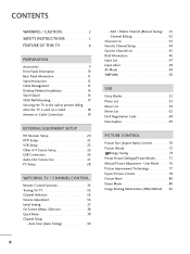
...Setup 23 VCR Setup 25 Other A/V Source Setup 26 USB Connection 26 Audio Out Connection 27 PC Setup 28 WATCHING TV / CHANNEL CONTROL Remote Control Functions 34 Turning On TV 36 Channel Selection 36 Volume Adjustment 36 Initial Setting 37 On-Screen Menus Selection 38 Quick Menu 39 ...Channel Setup - Auto Scan (Auto Tuning 40 - User Mode 76 Picture Improvement Technology 77 Expert Picture Control 78 Picture Reset 80 Demo Mode 80 Image Sticking Minimization (ISM) Method 81 6 Add / Delete Channel (Manual Tuning 41 - Channel Editing ...
...Setup 23 VCR Setup 25 Other A/V Source Setup 26 USB Connection 26 Audio Out Connection 27 PC Setup 28 WATCHING TV / CHANNEL CONTROL Remote Control Functions 34 Turning On TV 36 Channel Selection 36 Volume Adjustment 36 Initial Setting 37 On-Screen Menus Selection 38 Quick Menu 39 ...Channel Setup - Auto Scan (Auto Tuning 40 - User Mode 76 Picture Improvement Technology 77 Expert Picture Control 78 Picture Reset 80 Demo Mode 80 Image Sticking Minimization (ISM) Method 81 6 Add / Delete Channel (Manual Tuning 41 - Channel Editing ...
Owner's Manual
Page 9
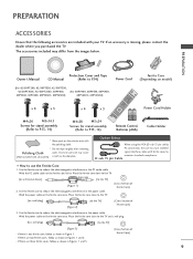
... in the PC audio cable. PREPARATION Owner's Manual Protection Cover and Tape CD Manual (Refer to P.14) Power Cord (For 42/50PT200, 42/50PT330, 42/50PT350, 42/50PT350C, 42/50PT250U, 50PV400, (For 60PV400, 60PV430, 60PV450, 50PV430, 50PV450, 50PV450C, 50PV550U) 60PV450C, 60PV550U) Ferrite Core (Depending on model) x ... ferrite core close to the TV and a wall plug. [to a wall plug] [to P.13, 14) 1.5V 1.5V Power Cord Holder Remote Control, Batteries (AAA) Cable Holder * Wipe spots on the ferrite core once. Wind the power cable on the exterior only with all models) scratch ...
... in the PC audio cable. PREPARATION Owner's Manual Protection Cover and Tape CD Manual (Refer to P.14) Power Cord (For 42/50PT200, 42/50PT330, 42/50PT350, 42/50PT350C, 42/50PT250U, 50PV400, (For 60PV400, 60PV430, 60PV450, 50PV430, 50PV450, 50PV450C, 50PV550U) 60PV450C, 60PV550U) Ferrite Core (Depending on model) x ... ferrite core close to the TV and a wall plug. [to a wall plug] [to P.13, 14) 1.5V 1.5V Power Cord Holder Remote Control, Batteries (AAA) Cable Holder * Wipe spots on the ferrite core once. Wind the power cable on the exterior only with all models) scratch ...
Owner's Manual
Page 10
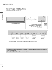
... step on . It may be damaged. 10 G Do not drag the TV. The floor or the product may break, causing possible injury from your finger. Remote Control Sensor HOME ENTER VOL CH POWER INPUT Button Button HOME Button ENTER Button VOLUME Buttons You can operate the buttons just by touching them lightly...
... step on . It may be damaged. 10 G Do not drag the TV. The floor or the product may break, causing possible injury from your finger. Remote Control Sensor HOME ENTER VOL CH POWER INPUT Button Button HOME Button ENTER Button VOLUME Buttons You can operate the buttons just by touching them lightly...
Owner's Manual
Page 12
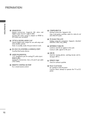
PREPARATION PREPARATION 1 HDMI/DVI IN Digital Connection. Uses a D-sub 15 pin cable (VGA cable). 5 REMOTE CONTROL IN PORT For a wired remote control. 6 COMPONENT IN Analog Connection. Supports standard definition video only (480i). 8 ANTENNA/CABLE IN Connect over-the air signals to MP3s. 10 ... Connect cable signals to this jack. 9 USB IN Used for viewing photos, waching movies and listening to this port doesn't work. 3 RS-232C IN (CONTROL & SERVICE) PORT Used by third party devices. 4 AUDIO IN (RGB/DVI) 1/8" headphone jack for analog PC audio input. Supports HD video and Digital...
PREPARATION PREPARATION 1 HDMI/DVI IN Digital Connection. Uses a D-sub 15 pin cable (VGA cable). 5 REMOTE CONTROL IN PORT For a wired remote control. 6 COMPONENT IN Analog Connection. Supports standard definition video only (480i). 8 ANTENNA/CABLE IN Connect over-the air signals to MP3s. 10 ... Connect cable signals to this jack. 9 USB IN Used for viewing photos, waching movies and listening to this port doesn't work. 3 RS-232C IN (CONTROL & SERVICE) PORT Used by third party devices. 4 AUDIO IN (RGB/DVI) 1/8" headphone jack for analog PC audio input. Supports HD video and Digital...
Owner's Manual
Page 20
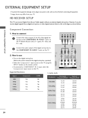
...) of the digital set -top box. Y PB PR L R 2 Connect the audio output of the digital settop box to use s Turn on the TV. 1 2 O IN /DVI) REMOTE CONTROL IN AV IN 1 VIDEO /MONO AUDIO 2 L R 1 VIDEO AUDIO COMPONENT IN ANT CA Supported Resolutions Signal 480i 480p 720p 1080i 1080p Component Yes Yes Yes Yes....94 60.00 24.00 30.00 59.939 60.00 23.94 29.97 20 How to the COMPONENT IN VIDEO 1 jacks on the remote control. s Image shown may differ from a digital set -top box.
...) of the digital set -top box. Y PB PR L R 2 Connect the audio output of the digital settop box to use s Turn on the TV. 1 2 O IN /DVI) REMOTE CONTROL IN AV IN 1 VIDEO /MONO AUDIO 2 L R 1 VIDEO AUDIO COMPONENT IN ANT CA Supported Resolutions Signal 480i 480p 720p 1080i 1080p Component Yes Yes Yes Yes....94 60.00 24.00 30.00 59.939 60.00 23.94 29.97 20 How to the COMPONENT IN VIDEO 1 jacks on the remote control. s Image shown may differ from a digital set -top box.
Owner's Manual
Page 21
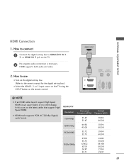
HDMI-DTV OUTPUT 1 OPTICAL DIGITAL AUDIO OUT AUDIO (RGB/DVI) 2 1 HDMI/DVI IN RS-232C IN (CONTROL & SERVICE) RGB IN(PC) ! In this case use I Select the HDMI1, 2, or 3 input source on the TV using the INPUT button on the TV. 2 No ...'s manual for the digital set-top box.) I Turn on the digital set-top box. (Refer to HDMI/DVI IN 1, 2, or HDMI IN 3 jack on the remote control.
HDMI-DTV OUTPUT 1 OPTICAL DIGITAL AUDIO OUT AUDIO (RGB/DVI) 2 1 HDMI/DVI IN RS-232C IN (CONTROL & SERVICE) RGB IN(PC) ! In this case use I Select the HDMI1, 2, or 3 input source on the TV using the INPUT button on the TV. 2 No ...'s manual for the digital set-top box.) I Turn on the digital set-top box. (Refer to HDMI/DVI IN 1, 2, or HDMI IN 3 jack on the remote control.
Owner's Manual
Page 22
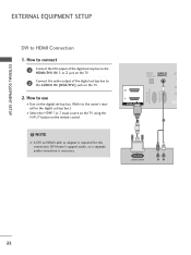
How to use I Select the HDMI1 or 2 input source on the TV using the INPUT button on the remote control. ! DVI doesn't support audio, so a separate audio connection is required for the digital set -top box to HDMI cable or adapter is necessary. NOTE G A DVI ... the digital set-top box. (Refer to the owner's manual for this connection. OPTICAL DIGITAL AUDIO OUT AUDIO IN (RGB/DVI) R CO RS-232C IN (CONTROL & SERVICE) RGB IN (PC) 2 2 1 1 HDMI/DVI IN 1 2 DVI-DTV OUTPUT R L 22 How to connect 1 Connect the DVI output of the digital set-top box to...
How to use I Select the HDMI1 or 2 input source on the TV using the INPUT button on the remote control. ! DVI doesn't support audio, so a separate audio connection is required for the digital set -top box to HDMI cable or adapter is necessary. NOTE G A DVI ... the digital set-top box. (Refer to the owner's manual for this connection. OPTICAL DIGITAL AUDIO OUT AUDIO IN (RGB/DVI) R CO RS-232C IN (CONTROL & SERVICE) RGB IN (PC) 2 2 1 1 HDMI/DVI IN 1 2 DVI-DTV OUTPUT R L 22 How to connect 1 Connect the DVI output of the digital set-top box to...
Owner's Manual
Page 23
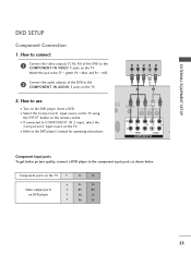
... outputs of the DVD to the COMPONENT IN AUDIO 1 jacks on the TV. Y PB PR L R 1 2 2. Component ports on the TV Y Y Video output ports Y on the remote control. How to use I If connected to COMPONENT IN 2 input, select the Component2 input source on the TV. DIO IN B/DVI...) REMOTE CONTROL IN AV IN 1 VIDEO /MONO AUDIO 2 L R 1 VIDEO AUDIO A COMPONENT IN Component Input ports To get better picture quality, connect a DVD player to the DVD player's ...
... outputs of the DVD to the COMPONENT IN AUDIO 1 jacks on the TV. Y PB PR L R 1 2 2. Component ports on the TV Y Y Video output ports Y on the remote control. How to use I If connected to COMPONENT IN 2 input, select the Component2 input source on the TV. DIO IN B/DVI...) REMOTE CONTROL IN AV IN 1 VIDEO /MONO AUDIO 2 L R 1 VIDEO AUDIO A COMPONENT IN Component Input ports To get better picture quality, connect a DVD player to the DVD player's ...
Owner's Manual
Page 24
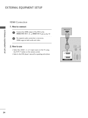
EXTERNAL EQUIPMENT SETUP EXTERNAL EQUIPMENT SETUP HDMI Connection 1. HDMI supports both audio and video. 2. I Select the HDMI1, 2, or 3 input source on the TV using the INPUT button on the TV. 2 No separate audio connection is necessary. HDMI-DVD OUTPUT 1 OPTICAL DIGITAL AUDIO OUT AUD (RGB/D 2 1 HDMI/DVI IN RS-232C IN (CONTROL & SERVICE) RGB IN (PC) 24 How to connect 1 Connect the HDMI output of the DVD to the DVD player's manual for operating instructions. How to use I Refer to the HDMI/DVI IN 1, 2, or HDMI IN 3 jack on the remote control.
EXTERNAL EQUIPMENT SETUP EXTERNAL EQUIPMENT SETUP HDMI Connection 1. HDMI supports both audio and video. 2. I Select the HDMI1, 2, or 3 input source on the TV using the INPUT button on the TV. 2 No separate audio connection is necessary. HDMI-DVD OUTPUT 1 OPTICAL DIGITAL AUDIO OUT AUD (RGB/D 2 1 HDMI/DVI IN RS-232C IN (CONTROL & SERVICE) RGB IN (PC) 24 How to connect 1 Connect the HDMI output of the DVD to the DVD player's manual for operating instructions. How to use I Refer to the HDMI/DVI IN 1, 2, or HDMI IN 3 jack on the remote control.
Owner's Manual
Page 25
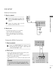
...IN 1 2 Connect the antenna cable to the RF antenna in socket of the TV. How to AV IN 2, select AV2 input source on the remote control. How to use I Insert a video tape into the VCR and press PLAY on the VCR. (Refer to the VCR owner's manual.) I If ...OUT S-VIDEO VIDEO L R ANT IN OUTPUT SWITCH 2 Wall Jack Antenna Composite (RCA) Connection 1. N (PC) ANT IN S-VIDEO VIDEO L R ANT OUT OUTPUT SWITCH 1 UDIO B/DVI) REMOTE CONTROL IN AV IN 1 VIDEO L//MMOONNOO AUDIO R 2 L R 1 25 I Select the A V 1 input source on the TV using the INPUT button on the TV. ! I Set VCR...
...IN 1 2 Connect the antenna cable to the RF antenna in socket of the TV. How to AV IN 2, select AV2 input source on the remote control. How to use I Insert a video tape into the VCR and press PLAY on the VCR. (Refer to the VCR owner's manual.) I If ...OUT S-VIDEO VIDEO L R ANT IN OUTPUT SWITCH 2 Wall Jack Antenna Composite (RCA) Connection 1. N (PC) ANT IN S-VIDEO VIDEO L R ANT OUT OUTPUT SWITCH 1 UDIO B/DVI) REMOTE CONTROL IN AV IN 1 VIDEO L//MMOONNOO AUDIO R 2 L R 1 25 I Select the A V 1 input source on the TV using the INPUT button on the TV. ! I Set VCR...

Owner's Manual
Page 26
... IN 2 VIDEO L/MONO AUDIO R HDMI IN 3 USB IN USB CONNECTION - How to AV IN 1 input, select the A V 1 input source on the remote control. EXTERNAL EQUIPMENT SETUP OTHER A/V SOURCE SETUP 1. For 42/50PT350, 42/50PT350C, 50/60PV450, 50/60PV450C, 42/50PT250U, 50/60PV550U 1. How to use I After connecting the USB I N jack, you use I Operate...
... IN 2 VIDEO L/MONO AUDIO R HDMI IN 3 USB IN USB CONNECTION - How to AV IN 1 input, select the A V 1 input source on the remote control. EXTERNAL EQUIPMENT SETUP OTHER A/V SOURCE SETUP 1. For 42/50PT350, 42/50PT350C, 50/60PV450, 50/60PV450C, 42/50PT250U, 50/60PV550U 1. How to use I After connecting the USB I N jack, you use I Operate...
Owner's Manual
Page 28
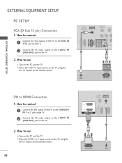
... on the PC and the TV. I Turn on the PC and the TV. OPTICAL DIGITAL AUDIO OUT AUDIO IN (RGB/DVI) REMOTE CONTROL IN VIDEO 2 2 1 VIDEO COMPONEN 1 RS-232C IN (CONTROL & SERVICE) RGB IN (PC) 2 1 AUDIO RGB OUTPUT DVI to the AUDIO IN (RGB/DVI) jack on the TV. 2. How to the AUDIO... output to use I Select the HDMI1 or 2 input source on the TV using the INPUT button on the remote control. 28 OPTICAL AUDIO IN DIGITAL AUDIO OUT (RGB/DVI) 2 1 HDMI/DVI IN RS-232C IN (CONTROL & SERVICE) RGB IN (PC) 1 2 DVI-PC OUTPUT AUDIO How to connect 1 Connect the DVI output of the...
... on the PC and the TV. I Turn on the PC and the TV. OPTICAL DIGITAL AUDIO OUT AUDIO IN (RGB/DVI) REMOTE CONTROL IN VIDEO 2 2 1 VIDEO COMPONEN 1 RS-232C IN (CONTROL & SERVICE) RGB IN (PC) 2 1 AUDIO RGB OUTPUT DVI to the AUDIO IN (RGB/DVI) jack on the TV. 2. How to the AUDIO... output to use I Select the HDMI1 or 2 input source on the TV using the INPUT button on the remote control. 28 OPTICAL AUDIO IN DIGITAL AUDIO OUT (RGB/DVI) 2 1 HDMI/DVI IN RS-232C IN (CONTROL & SERVICE) RGB IN (PC) 1 2 DVI-PC OUTPUT AUDIO How to connect 1 Connect the DVI output of the...

Owner's Manual
Page 34
...) menu. G p.49 INPUT Rotates through preset Video and Audio modes. WATCHING TV / CHANNEL CONTROL WATCHING TV / CHANNEL CONTROL REMOTE CONTROL FUNCTIONS When using the remote control, aim it at the remote control sensor on from standby or off to standby. AV MODE Toggles through inputs. Also switches the ...FLASHBK P CH A G E MUTE INFO Home Q.MENU ENTER BACK EXIT FREEZE 34 LIGHT Illuminates the remote control buttons. (Depending on from the images below. G p.47 TV Select the remote operating mode: TV NUMBER button - (DASH) Used to the last channel viewed. LIST Displays the...
...) menu. G p.49 INPUT Rotates through preset Video and Audio modes. WATCHING TV / CHANNEL CONTROL WATCHING TV / CHANNEL CONTROL REMOTE CONTROL FUNCTIONS When using the remote control, aim it at the remote control sensor on from standby or off to standby. AV MODE Toggles through inputs. Also switches the ...FLASHBK P CH A G E MUTE INFO Home Q.MENU ENTER BACK EXIT FREEZE 34 LIGHT Illuminates the remote control buttons. (Depending on from the images below. G p.47 TV Select the remote operating mode: TV NUMBER button - (DASH) Used to the last channel viewed. LIST Displays the...

Owner's Manual
Page 36
... the MUTE button. 3 You can cancel the Mute function by using the INPUT button on the remote control. 3 When finished using the TV, press the POWER button on the remote control. s In standby mode to be away on the remote control. 2 Select the viewing source by pressing the MUTE or VOL (+ or -) button. 36 The TV...
... the MUTE button. 3 You can cancel the Mute function by using the INPUT button on the remote control. 3 When finished using the TV, press the POWER button on the remote control. s In standby mode to be away on the remote control. 2 Select the viewing source by pressing the MUTE or VOL (+ or -) button. 36 The TV...
Owner's Manual
Page 50
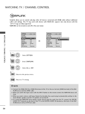
... fully supported. EXIT Return to the previous menu. G When you select a device with HDMI cable without additional cables and settings. WATCHING TV / CHANNEL CONTROL Simplink allows you to control and play the audio from the TV, connect the DIGITAL AUDIO OUT terminal on the back of the TV to the DIGITAL AUDIO... IN terminal on the back of the SIMPLINK device with the INPUT button on and off . SIMPLINK can be turned on the remote control, the SIMPLINK device will stop. NOTE G Connect the HDMI/DVI IN or HDMI IN terminal of the TV to the rear terminal (HDMI terminal) of...
... fully supported. EXIT Return to the previous menu. G When you select a device with HDMI cable without additional cables and settings. WATCHING TV / CHANNEL CONTROL Simplink allows you to control and play the audio from the TV, connect the DIGITAL AUDIO OUT terminal on the back of the TV to the DIGITAL AUDIO... IN terminal on the back of the SIMPLINK device with the INPUT button on and off . SIMPLINK can be turned on the remote control, the SIMPLINK device will stop. NOTE G Connect the HDMI/DVI IN or HDMI IN terminal of the TV to the rear terminal (HDMI terminal) of...
Owner's Manual
Page 53
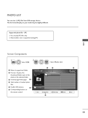
... memory. 1 6 Corresponding buttons on your model may be slightly different. USB PHOTO LIST You can play JPG files only. The On Screen Display on the remote control. Supported photo file: *.JPG I Only baseline scan is supported among JPG. PHOTO LIST Top Folder DriveA 3 4 Page 1/1 No Marked DriveA 1 2 folder, 4 file(s) Up Folder Move...
... memory. 1 6 Corresponding buttons on your model may be slightly different. USB PHOTO LIST You can play JPG files only. The On Screen Display on the remote control. Supported photo file: *.JPG I Only baseline scan is supported among JPG. PHOTO LIST Top Folder DriveA 3 4 Page 1/1 No Marked DriveA 1 2 folder, 4 file(s) Up Folder Move...

Owner's Manual
Page 59
... CH Move Page Q.MENU Option MARK Mark 5 USB Device Free Space 150MB Duration 04:12 05:30 Exit 6 59 The On Screen Display on the remote control. USB MUSIC LIST You can use the Music List menu to upper level folder. 2 Preview: Display the title/folder name of the music in the...
... CH Move Page Q.MENU Option MARK Mark 5 USB Device Free Space 150MB Duration 04:12 05:30 Exit 6 59 The On Screen Display on the remote control. USB MUSIC LIST You can use the Music List menu to upper level folder. 2 Preview: Display the title/folder name of the music in the...
Owner's Manual
Page 63
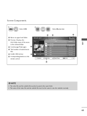
... must be the same to upper level folder. 2 Preview: Display the title/folder name of marked movie files. 5 Usable USB memory. 1 6 Corresponding buttons on the remote control. USB Screen Components 1 Home Select U S B. 2 ENTER ENTER Select Mo v i e Li s t. 1 Moves to view the subtitles normally 63
... must be the same to upper level folder. 2 Preview: Display the title/folder name of marked movie files. 5 Usable USB memory. 1 6 Corresponding buttons on the remote control. USB Screen Components 1 Home Select U S B. 2 ENTER ENTER Select Mo v i e Li s t. 1 Moves to view the subtitles normally 63

Owner's Manual
Page 65
...-> GGG -> GGGG -> GGGGG -> GGGGGG. I When using the or buttons during playback a cursor indicating the position can adjust various method during movie play. USB Using the remote control You can be viewed on the screen.
...-> GGG -> GGGG -> GGGGG -> GGGGGG. I When using the or buttons during playback a cursor indicating the position can adjust various method during movie play. USB Using the remote control You can be viewed on the screen.
Owner's Manual
Page 70
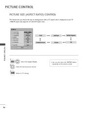
... the RATIO button repeatedly on your TV. Select the desired picture format. 3 EXIT Return to TV viewing. PICTURE CONTROL PICTURE SIZE (ASPECT RATIO) CONTROL This feature lets you choose the way an analog picture with a 4:3 aspect ratio is displayed on the remote control. PICTURE CONTROL 70 s RGB-PC input only supports 4:3 and 16:9 aspect ratio.
... the RATIO button repeatedly on your TV. Select the desired picture format. 3 EXIT Return to TV viewing. PICTURE CONTROL PICTURE SIZE (ASPECT RATIO) CONTROL This feature lets you choose the way an analog picture with a 4:3 aspect ratio is displayed on the remote control. PICTURE CONTROL 70 s RGB-PC input only supports 4:3 and 16:9 aspect ratio.


