User Manual
Page 1
... : 50PQ1000-ZD 6632 : 42PQ1100-ZE 6633 : 50PQ1100-ZE 6023: 42PQ2000-ZA 6320 : 42PQ2010-ZB 6024: 50PQ2000-ZA 6319 : 50PQ2010-ZB 6025: 42PQ3000-ZA 6020: 50PQ3000-ZA 6026: 42PQ6000-ZA 6875 : 42PQ6010-ZB 6029: 50PQ6000-ZA 6884 : 50PS2000-ZB 6322 : 50PS3000-ZB 6341: 50PS6000-ZC 6609... : 60PS4000-ZA PLASMA TV OWNER'S MANUAL PLASMA TV MODELS 42PQ10** 50PQ10** 42PQ11** 50PQ11** 42PQ20** 50PQ20** 42PQ30** 50PQ30** 42PQ60** 50PQ60** 50PS20** 50PS30** 50PS60** 60PS40** Please read this manual...
... : 50PQ1000-ZD 6632 : 42PQ1100-ZE 6633 : 50PQ1100-ZE 6023: 42PQ2000-ZA 6320 : 42PQ2010-ZB 6024: 50PQ2000-ZA 6319 : 50PQ2010-ZB 6025: 42PQ3000-ZA 6020: 50PQ3000-ZA 6026: 42PQ6000-ZA 6875 : 42PQ6010-ZB 6029: 50PQ6000-ZA 6884 : 50PS2000-ZB 6322 : 50PS3000-ZB 6341: 50PS6000-ZC 6609... : 60PS4000-ZA PLASMA TV OWNER'S MANUAL PLASMA TV MODELS 42PQ10** 50PQ10** 42PQ11** 50PQ11** 42PQ20** 50PQ20** 42PQ30** 50PQ30** 42PQ60** 50PQ60** 50PS20** 50PS30** 50PS60** 60PS40** Please read this manual...

User Manual
Page 3
... not use on the screen. * Lightly wipe any stains or fingerprints on the surface of the TV with your TV. This may differ from your TV. This item is missing, please contact the dealer where you purchased the TV. I Image shown may cause scratching or discolouration. If an accessory is not included for all...
... not use on the screen. * Lightly wipe any stains or fingerprints on the surface of the TV with your TV. This may differ from your TV. This item is missing, please contact the dealer where you purchased the TV. I Image shown may cause scratching or discolouration. If an accessory is not included for all...
User Manual
Page 4
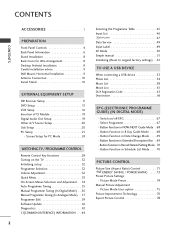
...Aspect Ratio) Control 71 ENERGY SAVING / POWER SAVING . . . . .73 Preset Picture Settings - Button Function in NOW/NEXT Guide Mode . 68 - Switch on the TV 32 Initializing setup 32 Programme Selection 32 Volume Adjustment 32 Quick Menu 33 On-Screen Menus Selection and Adjustment . . 34 Auto Programme Tuning 35 Manual... Day Guide Mode . . . . 68 - CONTENTS CONTENTS ACCESSORIES 1 PREPARATION Front Panel Controls 4 Back Panel Information 6 Stand Installation 8 Back Cover for PC Mode 24 WATCHING TV / PROGRAMME CONTROL Remote Control Key Functions 28 Turning on /off EPG 67 -
...Aspect Ratio) Control 71 ENERGY SAVING / POWER SAVING . . . . .73 Preset Picture Settings - Button Function in NOW/NEXT Guide Mode . 68 - Switch on the TV 32 Initializing setup 32 Programme Selection 32 Volume Adjustment 32 Quick Menu 33 On-Screen Menus Selection and Adjustment . . 34 Auto Programme Tuning 35 Manual... Day Guide Mode . . . . 68 - CONTENTS CONTENTS ACCESSORIES 1 PREPARATION Front Panel Controls 4 Back Panel Information 6 Stand Installation 8 Back Cover for PC Mode 24 WATCHING TV / PROGRAMME CONTROL Remote Control Key Functions 28 Turning on /off EPG 67 -
User Manual
Page 5
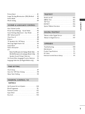
Sound Mode 86 Sound Setting Adjustment -User Mode 87 SRS TruSurround XT 87 Clear Voice II 88 Balance 88 TV Speakers On/ Off Setup 89 Selecting Digital Audio Out 90 Audio Reset 91 Audio description 92 I/II - Stereo/Dual Reception (In Analogue Mode Only) . . . . 93 - ...
Sound Mode 86 Sound Setting Adjustment -User Mode 87 SRS TruSurround XT 87 Clear Voice II 88 Balance 88 TV Speakers On/ Off Setup 89 Selecting Digital Audio Out 90 Audio Reset 91 Audio description 92 I/II - Stereo/Dual Reception (In Analogue Mode Only) . . . . 93 - ...

User Manual
Page 6
... Illuminates red in standby mode. PREPARATION PREPARATION FRONT PANEL CONTROLS I Image shown may differ from your TV. POWER POWER INPUT MENU OK P INPUT INPUT MENU OK MENU OK VOLUME PROGRAMME P POWER 4 CAUTION G When the TV cannot be turned on with the remote control, press the main power button on the... TV (When the power is turned off with the main power button on the TV, it will not be turned on with the remote control.) 42/50PQ11**, 42/50PQ30**, 50PS30** Remote Control Sensor Intelligent ...
... Illuminates red in standby mode. PREPARATION PREPARATION FRONT PANEL CONTROLS I Image shown may differ from your TV. POWER POWER INPUT MENU OK P INPUT INPUT MENU OK MENU OK VOLUME PROGRAMME P POWER 4 CAUTION G When the TV cannot be turned on with the remote control, press the main power button on the... TV (When the power is turned off with the main power button on the TV, it will not be turned on with the remote control.) 42/50PQ11**, 42/50PQ30**, 50PS30** Remote Control Sensor Intelligent ...

User Manual
Page 7
... Control Sensor Intelligent Sensor Adjusts picture according to the surrounding conditions Power/Standby Indicator • Illuminates red in standby mode. • illuminates green when the TV is off while the...
... Control Sensor Intelligent Sensor Adjusts picture according to the surrounding conditions Power/Standby Indicator • Illuminates red in standby mode. • illuminates green when the TV is off while the...

User Manual
Page 8
.../50PQ10**, 42/50PQ11** USB IN SERVICE ONLY PREPARATION USB IN SERVICE ONLY 1 7 2 3 USB IN SERVICE ONLY 8 HDMI IN (CONTROL & SERVICE) 4 5 1 Power Cord Socket This TV operates on the Specifications page. Connect to PCMCIA CARD SLOT. (This feature is indicated on an AC power. The voltage is not available in all .... 6 5 RS-232C IN (CONTROL & SERVICE) PORT Connect to the RS-232C port on DC power. 2 OPTICAL DIGITAL AUDIO OUT Connect digital audio to operate the TV on a PC.
.../50PQ10**, 42/50PQ11** USB IN SERVICE ONLY PREPARATION USB IN SERVICE ONLY 1 7 2 3 USB IN SERVICE ONLY 8 HDMI IN (CONTROL & SERVICE) 4 5 1 Power Cord Socket This TV operates on the Specifications page. Connect to PCMCIA CARD SLOT. (This feature is indicated on an AC power. The voltage is not available in all .... 6 5 RS-232C IN (CONTROL & SERVICE) PORT Connect to the RS-232C port on DC power. 2 OPTICAL DIGITAL AUDIO OUT Connect digital audio to operate the TV on a PC.

User Manual
Page 9
... L/MONO AUDIO R S-VIDEO HDMI IN 3 11 2 3 4 5 HDMI IN 2 1 12 HDMI/DVI IN AV IN 3 5 6 7 8 9 1 Power Cord Socket This TV operates on the Specifications page. The voltage is used for Service or Hotel mode. 8 Component Input Connect a component video/audio device to these jacks. Connect...signal to these jacks. 3 OPTICAL DIGITAL AUDIO OUT 9 Antenna Input Connect digital audio to various types of equipment. Never attempt to operate the TV on a PC. Use an Optical audio cable. 4 Euro Scart Socket (AV1/AV2) Connect scart socket input or output from an S-VIDEO device...
... L/MONO AUDIO R S-VIDEO HDMI IN 3 11 2 3 4 5 HDMI IN 2 1 12 HDMI/DVI IN AV IN 3 5 6 7 8 9 1 Power Cord Socket This TV operates on the Specifications page. The voltage is used for Service or Hotel mode. 8 Component Input Connect a component video/audio device to these jacks. Connect...signal to these jacks. 3 OPTICAL DIGITAL AUDIO OUT 9 Antenna Input Connect digital audio to various types of equipment. Never attempt to operate the TV on a PC. Use an Optical audio cable. 4 Euro Scart Socket (AV1/AV2) Connect scart socket input or output from an S-VIDEO device...
User Manual
Page 10
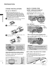
...CABLE MANAGEMENT CLIP to distinguish and assemble the front and rear side of the bolt. 1 Carefully place the TV screen side down on a cushioned surface to protect the screen from your TV. Only 60PS40** CABLE HOLDER Install the CABLE MANAGEMENT CLIP as shown. MENT CLIP 3 Fix the 4 bolts...bolt can tilt forward after the product installation.) If you may be damaged. Insert the PROTECTION COVER into the TV until clicking sound. 8 protection cover CABLE MANAGE- If the TV is fully tightened. (If not tightened fully, the product can deviate from abrasion of the tightening part of ...
...CABLE MANAGEMENT CLIP to distinguish and assemble the front and rear side of the bolt. 1 Carefully place the TV screen side down on a cushioned surface to protect the screen from your TV. Only 60PS40** CABLE HOLDER Install the CABLE MANAGEMENT CLIP as shown. MENT CLIP 3 Fix the 4 bolts...bolt can tilt forward after the product installation.) If you may be damaged. Insert the PROTECTION COVER into the TV until clicking sound. 8 protection cover CABLE MANAGE- If the TV is fully tightened. (If not tightened fully, the product can deviate from abrasion of the tightening part of ...
User Manual
Page 11
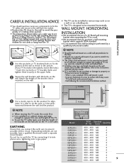
... the height of it to the wall, avoiding the possibility of a LG Brand wall mounting bracket when mounting the TV to telephone wires, lightening rods or gas pipes. This will prevent the TV from the market. A The TV is safer to tie the rope so it to a wall. A ... below are not possible, have a qualified electrician install a separate circuit breaker. A The TV can be mounted horizontally. WALL MOUNT: HORIZONTAL INSTALLATION A We recommend the use of it to surface which supports VESA standard. G LG is the same. G Use a platform or cabinet strong and large enough to support the...
... the height of it to the wall, avoiding the possibility of a LG Brand wall mounting bracket when mounting the TV to telephone wires, lightening rods or gas pipes. This will prevent the TV from the market. A The TV is safer to tie the rope so it to a wall. A ... below are not possible, have a qualified electrician install a separate circuit breaker. A The TV can be mounted horizontally. WALL MOUNT: HORIZONTAL INSTALLATION A We recommend the use of it to surface which supports VESA standard. G LG is the same. G Use a platform or cabinet strong and large enough to support the...

User Manual
Page 12
I If signal needs to be necessary to install a signal amplifier to achieve better picture quality it may be split for two TVs,use an antenna signal splitter for outdoor antenna) Antenna UHF Signal Amplifier VHF I In poor signal areas, to the antenna as shown above....to wall jack for connection. ANTENNA CONNECTION I An antenna cable and converter are made between the devices. SWIVEL STAND After installing the TV, you can adjust the TV manually to the left or right direction by 20 degrees to the mains outlet until all connections are not supplied. PREPARATION PREPARATION I...
I If signal needs to be necessary to install a signal amplifier to achieve better picture quality it may be split for two TVs,use an antenna signal splitter for outdoor antenna) Antenna UHF Signal Amplifier VHF I In poor signal areas, to the antenna as shown above....to wall jack for connection. ANTENNA CONNECTION I An antenna cable and converter are made between the devices. SWIVEL STAND After installing the TV, you can adjust the TV manually to the left or right direction by 20 degrees to the mains outlet until all connections are not supplied. PREPARATION PREPARATION I...
User Manual
Page 13
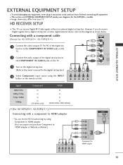
HD RECEIVER SETUP I This TV can inquire and purchase Component to HDMI adapter at Website or Market.) HDMI OUT Component to the diagram as shown below. I This section ... PB, PR) of the digital set 1 top box to the COMPONENT IN VIDEO jacks on the TV. 2 Connect the audio output of the digital set-top box to 2 the COMPONENT IN AUDIO jacks on the TV. 3 Turn on the digital set-top box. (Refer to HDMI adapter. (You can receive Digital... SETUP EXTERNAL EQUIPMENT SETUP I To avoid damaging any equipment, never plug in any power cords until you do receive Digital signals from your TV.
HD RECEIVER SETUP I This TV can inquire and purchase Component to HDMI adapter at Website or Market.) HDMI OUT Component to the diagram as shown below. I This section ... PB, PR) of the digital set 1 top box to the COMPONENT IN VIDEO jacks on the TV. 2 Connect the audio output of the digital set-top box to 2 the COMPONENT IN AUDIO jacks on the TV. 3 Turn on the digital set-top box. (Refer to HDMI adapter. (You can receive Digital... SETUP EXTERNAL EQUIPMENT SETUP I To avoid damaging any equipment, never plug in any power cords until you do receive Digital signals from your TV.
User Manual
Page 14
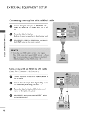
...HDMI cable 1 Connect the digital set-top box to HDMI/DVI IN 1, HDMI IN, HDMI IN 2 or HDMI IN 3 jack on the TV. 2 Turn on the digital set-top box. (Refer to the owner's manual for the digital set -top box.) 4 Select HDMI1 input... 42/50PQ10**, 42/50PQ11**) 1 Connect the digital set-top box to HDMI/DVI IN 1 jack on the TV. 2 Connect the audio output of the digital set-top box to the AUDIO IN (RGB/DVI) jack on the... TV. 3 Turn on the digital set-top box. (Refer to the owner's manual for the digital set -top box.)...
...HDMI cable 1 Connect the digital set-top box to HDMI/DVI IN 1, HDMI IN, HDMI IN 2 or HDMI IN 3 jack on the TV. 2 Turn on the digital set-top box. (Refer to the owner's manual for the digital set -top box.) 4 Select HDMI1 input... 42/50PQ10**, 42/50PQ11**) 1 Connect the digital set-top box to HDMI/DVI IN 1 jack on the TV. 2 Connect the audio output of the digital set-top box to the AUDIO IN (RGB/DVI) jack on the... TV. 3 Turn on the digital set-top box. (Refer to the owner's manual for the digital set -top box.)...

User Manual
Page 15
...'s manual for 42/50PQ10**, 42/50PQ11**) 1 Connect the video outputs (Y, PB, PR) of the DVD to the COMPONENT IN VIDEO jacks on the TV. 2 Connect the audio outputs of the DVD to the component input ports as shown below. tions. 1 2 Component Input ports To achieve better picture ...quality, connect a DVD player to the COMPONENT IN AUDIO jacks on the TV. 3 Turn on the DVD player, insert a DVD. 4 Select Component input source using the INPUT button on DVD player Y PB PR Y B-Y R-Y Y Cb Cr ...
...'s manual for 42/50PQ10**, 42/50PQ11**) 1 Connect the video outputs (Y, PB, PR) of the DVD to the COMPONENT IN VIDEO jacks on the TV. 2 Connect the audio outputs of the DVD to the component input ports as shown below. tions. 1 2 Component Input ports To achieve better picture ...quality, connect a DVD player to the COMPONENT IN AUDIO jacks on the TV. 3 Turn on the DVD player, insert a DVD. 4 Select Component input source using the INPUT button on DVD player Y PB PR Y B-Y R-Y Y Cb Cr ...

User Manual
Page 16
...Out: Outputs the current screen image. G AV3, Component, RGB : Except for operating instructions. Output Type Current input mode Digital TV Analogue TV AV1 (TV Out) X O AV2 (Monitor Out) O O AV2 (When DTV scheduled recording is in progress using the INPUT button on the...to A V 2 Euro scart socket, select A V 2 input source. 1 4 Refer to DTV automatically.) AV1/2/3 O O O Component/RGB/HDMI O X O G TV Out : Outputs analog TV video signals. AUDIO/ VIDEO (R) AUDIO (L) Input Scart Video Audio RGB AV1 O O O Output Video, Audio ATV only AV2 O O X ATV, DTV, AV1/2/3 output...
...Out: Outputs the current screen image. G AV3, Component, RGB : Except for operating instructions. Output Type Current input mode Digital TV Analogue TV AV1 (TV Out) X O AV2 (Monitor Out) O O AV2 (When DTV scheduled recording is in progress using the INPUT button on the...to A V 2 Euro scart socket, select A V 2 input source. 1 4 Refer to DTV automatically.) AV1/2/3 O O O Component/RGB/HDMI O X O G TV Out : Outputs analog TV video signals. AUDIO/ VIDEO (R) AUDIO (L) Input Scart Video Audio RGB AV1 O O O Output Video, Audio ATV only AV2 O O X ATV, DTV, AV1/2/3 output...

User Manual
Page 17
...must set the output resolution appropriately. Please use the latest cables that your HDMI cable is version 1.3 or higher. NOTE 1 G The TV can result. If the HDMI cables don't support HDMI version 1.3, flickering or no screen display can receive video and audio signals simultaneously when...manual for operating instructions. AV IN 3 Connecting the HDMI cable 1 Connect the HDMI output of the DVD to the AUDIO input jacks on the TV. 3 Turn on the remote control. 3 Refer to the DVD player's manual for operating instruc- EXTERNAL EQUIPMENT SETUP Connecting with a S-Video ...
...must set the output resolution appropriately. Please use the latest cables that your HDMI cable is version 1.3 or higher. NOTE 1 G The TV can result. If the HDMI cables don't support HDMI version 1.3, flickering or no screen display can receive video and audio signals simultaneously when...manual for operating instructions. AV IN 3 Connecting the HDMI cable 1 Connect the HDMI output of the DVD to the AUDIO input jacks on the TV. 3 Turn on the remote control. 3 Refer to the DVD player's manual for operating instruc- EXTERNAL EQUIPMENT SETUP Connecting with a S-Video ...

User Manual
Page 18
EXTERNAL EQUIPMENT SETUP EXTERNAL EQUIPMENT SETUP VCR SETUP I To avoid picture noise (interference), allow adequate distance between the TV and VCR for viewing. Connecting with a RF Cable 1 ANT OUT S-VIDEO VIDEO L R ANT IN OUTPUT SWITCH Wall Jack 2 Antenna 1 Connect the ANT OUT socket of the VCR to the ANTENNA IN socket on the TV. 2 Connect the antenna cable to the ANT IN socket of the VCR. 3 Press the PLAY button on the VCR and match the appropriate channel between the VCR and TV. R S-VIDEO HDMI IN 3 16
EXTERNAL EQUIPMENT SETUP EXTERNAL EQUIPMENT SETUP VCR SETUP I To avoid picture noise (interference), allow adequate distance between the TV and VCR for viewing. Connecting with a RF Cable 1 ANT OUT S-VIDEO VIDEO L R ANT IN OUTPUT SWITCH Wall Jack 2 Antenna 1 Connect the ANT OUT socket of the VCR to the ANTENNA IN socket on the TV. 2 Connect the antenna cable to the ANT IN socket of the VCR. 3 Press the PLAY button on the VCR and match the appropriate channel between the VCR and TV. R S-VIDEO HDMI IN 3 16

User Manual
Page 19
EXTERNAL EQUIPMENT SETUP Connecting with a Euro Scart cable 1 Connect the Euro scart socket of the VCR to the A V 1 Euro scart socket on the TV. 2 Insert a video tape into the VCR and press PLAY on the remote control. 4 If connected to AV2 Euro scart socket, select AV2 input source... equipment.) O O (The input mode is available. NOTE G Any Euro Scart cable used must be signal shielded. 17 Output Type Current input mode Digital TV Analogue TV AV1 (TV Out) X O AV2 (Monitor Out) O O AV2 (When DTV scheduled recording is in progress using the INPUT button on the VCR. (Refer to DTV...
EXTERNAL EQUIPMENT SETUP Connecting with a Euro Scart cable 1 Connect the Euro scart socket of the VCR to the A V 1 Euro scart socket on the TV. 2 Insert a video tape into the VCR and press PLAY on the remote control. 4 If connected to AV2 Euro scart socket, select AV2 input source... equipment.) O O (The input mode is available. NOTE G Any Euro Scart cable used must be signal shielded. 17 Output Type Current input mode Digital TV Analogue TV AV1 (TV Out) X O AV2 (Monitor Out) O O AV2 (When DTV scheduled recording is in progress using the INPUT button on the VCR. (Refer to DTV...

User Manual
Page 20
... (RCA cable) input. AV IN 3 ! VIDEO L/MONO AUDIO R S-VIDEO HDMI IN 3 2 Connect the audio outputs of the VCR to the AUDIO input jacks on the TV. 3 Insert a video tape into the VCR and press PLAY on the VCR. (Refer to the VCR owner's manual.) AV IN 3 3 Select A V 3 input source ... VCR to the VCR owner's manual.) 4 Select AV3 input source with a S-Video cable (Except for 42/50PQ10**, 42/50PQ11**) 1 Connect the AUDIO/VIDEO jacks between TV and VCR. Match the jack colours (Video = yellow, Audio Left = white, and Audio Right = red) 2 Insert a video tape into the VCR and press PLAY...
... (RCA cable) input. AV IN 3 ! VIDEO L/MONO AUDIO R S-VIDEO HDMI IN 3 2 Connect the audio outputs of the VCR to the AUDIO input jacks on the TV. 3 Insert a video tape into the VCR and press PLAY on the VCR. (Refer to the VCR owner's manual.) AV IN 3 3 Select A V 3 input source ... VCR to the VCR owner's manual.) 4 Select AV3 input source with a S-Video cable (Except for 42/50PQ10**, 42/50PQ11**) 1 Connect the AUDIO/VIDEO jacks between TV and VCR. Match the jack colours (Video = yellow, Audio Left = white, and Audio Right = red) 2 Insert a video tape into the VCR and press PLAY...

User Manual
Page 21
... of the optical cable to the digi- If you want to the TV Digital Audio (Optical) Output port. 2 Connect the other end of TV as shown. DIGITAL AUDIO OUT SETUP Sending the TV's audio signal to the TV and the PCMCIA card slot. Looking at the laser beam may damage your... of an optical cable to enjoy digital broadcasting through 5.1-channel speakers, connect the OPTICAL DIGITAL AUDIO OUT terminal on the audio equipment. 3 Set the "TV Speaker option - EXTERNAL EQUIPMENT SETUP INSERTION OF CI MODULE - NOTE G Check if the CI module is not included for operation. 2 CAUTION GDo not...
... of the optical cable to the digi- If you want to the TV Digital Audio (Optical) Output port. 2 Connect the other end of TV as shown. DIGITAL AUDIO OUT SETUP Sending the TV's audio signal to the TV and the PCMCIA card slot. Looking at the laser beam may damage your... of an optical cable to enjoy digital broadcasting through 5.1-channel speakers, connect the OPTICAL DIGITAL AUDIO OUT terminal on the audio equipment. 3 Set the "TV Speaker option - EXTERNAL EQUIPMENT SETUP INSERTION OF CI MODULE - NOTE G Check if the CI module is not included for operation. 2 CAUTION GDo not...


