Owners Manual
Page 1
... information on the advanced features of these files, you require service. LCD TV PLASMA TV OWNER'S MANUAL LCD TV MODELS 32LG30 37LG30 42LG30 37LG50 42LG50 47LG50 52LG50 32LG60 37LG60 42LG60 47LG60 52LG60 32LG70 42LG70 47LG70 52LG70 PLASMA TV MODELS 42PG25 50PG25 50PG60 60PG60 Please read these LG TV sets is a set of the set . See the label attached on...
... information on the advanced features of these files, you require service. LCD TV PLASMA TV OWNER'S MANUAL LCD TV MODELS 32LG30 37LG30 42LG30 37LG50 42LG50 47LG50 52LG50 32LG60 37LG60 42LG60 47LG60 52LG60 32LG70 42LG70 47LG70 52LG70 PLASMA TV MODELS 42PG25 50PG25 50PG60 60PG60 Please read these LG TV sets is a set of the set . See the label attached on...

Owners Manual
Page 2
... alert the user to persons. Any changes or modifications not expressly approved by turning the equipment off and on a circuit different from LG Electronics. Unauthorized modification could void the user's authority to constitute a risk of the following measures: - REFER TO QUALIFIED SERVICE PERSONNEL.... from that the cable ground shall be of sufficient magnitude to operate the equipment. Consult the dealer or an experienced radio/TV technician for compliance could void the user's authority to operate this product to the grounding system of the building, as practical...
... alert the user to persons. Any changes or modifications not expressly approved by turning the equipment off and on a circuit different from LG Electronics. Unauthorized modification could void the user's authority to constitute a risk of the following measures: - REFER TO QUALIFIED SERVICE PERSONNEL.... from that the cable ground shall be of sufficient magnitude to operate the equipment. Consult the dealer or an experienced radio/TV technician for compliance could void the user's authority to operate this product to the grounding system of the building, as practical...

Owners Manual
Page 3
...apparatus. The following safety instruction list. Install in an instruction for installation for use attachments/accessories specified by the manufacturer. 5 When mounting a TV it on the back of the obsolete outlet. A grounding type plug has two blades and a third grounding prong, The wide blade or... and, when used . This information shall be included by hanging power and signal cables on the wall, make sure not to install TV by adding statements after the end of a specific safety instruction may be given in a separate booklet or sheet, or be entitled "Important...
...apparatus. The following safety instruction list. Install in an instruction for installation for use attachments/accessories specified by the manufacturer. 5 When mounting a TV it on the back of the obsolete outlet. A grounding type plug has two blades and a third grounding prong, The wide blade or... and, when used . This information shall be included by hanging power and signal cables on the wall, make sure not to install TV by adding statements after the end of a specific safety instruction may be given in a separate booklet or sheet, or be entitled "Important...

Owners Manual
Page 4
...plug is turned on the screen. Check the specification page of the appliance, and have a qualified electrician install a separate circuit breaker. FOR LCD TV I Some minute dot defects may produce some temporary distortion effects on . MFL34797048-en-4 3/18/08 7:26 PM Page 4 SAFETY INSTRUCTIONS 10 ...Use only with the cart, stand, tripod, bracket, or table specified by the manufacturer, or sold with TV. The plug must be placed on the monitor's performance. Protect the power cord from tip-over apparatus. 17 GROUNDING Ensure that appliance and ...
...plug is turned on the screen. Check the specification page of the appliance, and have a qualified electrician install a separate circuit breaker. FOR LCD TV I Some minute dot defects may produce some temporary distortion effects on . MFL34797048-en-4 3/18/08 7:26 PM Page 4 SAFETY INSTRUCTIONS 10 ...Use only with the cart, stand, tripod, bracket, or table specified by the manufacturer, or sold with TV. The plug must be placed on the monitor's performance. Protect the power cord from tip-over apparatus. 17 GROUNDING Ensure that appliance and ...

Owners Manual
Page 5
... Cable Management 14 Desktop Pedestal Installation 16 Swivel Stand 16 Attaching the TV to a Desk 16 VESA Wall Mounting 17 Protection Cover 18 Securing the TV to the Wall to install those programs, Open the "My Computer" Open the "LG" Open the "ACRORD" double-click your language. You can find ... . 19 Antenna or Cable Connection 20 EXTERNAL EQUIPMENT SETUP HD Receiver Setup 21 DVD Setup 22 VCR Setup 23 PC Setup 24 WATCHING TV Turning On TV 26 Channel Setup 26 Quick Menu 27 On-Screen Menus Selection 27 USB Entry Modes 30 Photo List 31 Music List 33 APPENDIX Troubleshooting...
... Cable Management 14 Desktop Pedestal Installation 16 Swivel Stand 16 Attaching the TV to a Desk 16 VESA Wall Mounting 17 Protection Cover 18 Securing the TV to the Wall to install those programs, Open the "My Computer" Open the "LG" Open the "ACRORD" double-click your language. You can find ... . 19 Antenna or Cable Connection 20 EXTERNAL EQUIPMENT SETUP HD Receiver Setup 21 DVD Setup 22 VCR Setup 23 PC Setup 24 WATCHING TV Turning On TV 26 Channel Setup 26 Quick Menu 27 On-Screen Menus Selection 27 USB Entry Modes 30 Photo List 31 Music List 33 APPENDIX Troubleshooting...

Owners Manual
Page 6
... differ from the images below. For Plasma TV models x 4 Bolts for stand assembly (Refer to P.12) (Only 42PG25) Cable Holder (Only 42PG25) (Only 50PG25, 50/60PG60) Cable Management Clip Protection Cover (Refer to P.18) For LCD TV models 32/37/42LG30, 37/42/47/52LG50, 32/42/47/52LG70 (Only 32/37/42LG30,...stain. For further information, see the the Owner's Manual files supplied CD-ROM. RETURN TV Q. Owner's Manual CD Manual (Refer to p.5) * Wipe spots on the exterior only with ferrite cores to P.18) 32/37/42/47/52LG60 (Only 32/37LG60) (Only 42LG60) or 32LG60: 3EA 4EA 37LG60: 4EA...
... differ from the images below. For Plasma TV models x 4 Bolts for stand assembly (Refer to P.12) (Only 42PG25) Cable Holder (Only 42PG25) (Only 50PG25, 50/60PG60) Cable Management Clip Protection Cover (Refer to P.18) For LCD TV models 32/37/42LG30, 37/42/47/52LG50, 32/42/47/52LG70 (Only 32/37/42LG30,...stain. For further information, see the the Owner's Manual files supplied CD-ROM. RETURN TV Q. Owner's Manual CD Manual (Refer to p.5) * Wipe spots on the exterior only with ferrite cores to P.18) 32/37/42/47/52LG60 (Only 32/37LG60) (Only 42LG60) or 32LG60: 3EA 4EA 37LG60: 4EA...

Owners Manual
Page 7
... CHANNEL Button Button Button (-, +) Buttons (E,D)Buttons 32/37/42LG30, 37/42/47/52LG50, 32/42/47/52LG70 CH Remote Control Sensor POWER Button Power/Standby Indicator Illuminates red in standby mode. And then wipe the TV with a cloth (If a polishing cloth is switched on . (Can ...Button 32/37/42/47/52LG60 CH CHANNEL ( , ) Buttons VOLUME (+, -) Buttons VOL POWER Button Remote Control Sensor Power/Standby Indicator Illuminates red in MENU Button MENU the OPTION menu.) INPUT Button INPUT 7 Illuminates blue when the TV is included with your TV, use it). Plasma TV Models Remote ...
... CHANNEL Button Button Button (-, +) Buttons (E,D)Buttons 32/37/42LG30, 37/42/47/52LG50, 32/42/47/52LG70 CH Remote Control Sensor POWER Button Power/Standby Indicator Illuminates red in standby mode. And then wipe the TV with a cloth (If a polishing cloth is switched on . (Can ...Button 32/37/42/47/52LG60 CH CHANNEL ( , ) Buttons VOLUME (+, -) Buttons VOL POWER Button Remote Control Sensor Power/Standby Indicator Illuminates red in MENU Button MENU the OPTION menu.) INPUT Button INPUT 7 Illuminates blue when the TV is included with your TV, use it). Plasma TV Models Remote ...

Owners Manual
Page 9
... cable signals to this jack. MFL34797048-en-4 3/18/08 7:27 PM Page 9 R RGB IN HDMI/DVI IN PREPARATION 32/42/47/52LG70 1 HDMI/DVI IN 3 2 1 3 5 ANTENNA/ CABLE IN 6 4 RGB IN DIGITAL AUDIO OUT RGB(PC... AUDIO OUT (CONTROL & SERVICE) 8 2 AV IN 1 1 VIDEO AUDIO COMPONENT IN 2 9 S-VIDEO VIDEO (MONO) AUDIO 32/37/42/47/52LG60 2 1 2 1 VIDEO COMPONENT IN 1 23 DIGITAL AUDIO OUT AUDIO (RGB/DVI) AUDIO COAXIAL 11 3 OPTICAL RGB(PC) RS...systems. Accepts DVI video using an adapter or HDMI to operate the TV on DC power. 9 Supports standard Analog PC Connection.
... cable signals to this jack. MFL34797048-en-4 3/18/08 7:27 PM Page 9 R RGB IN HDMI/DVI IN PREPARATION 32/42/47/52LG70 1 HDMI/DVI IN 3 2 1 3 5 ANTENNA/ CABLE IN 6 4 RGB IN DIGITAL AUDIO OUT RGB(PC... AUDIO OUT (CONTROL & SERVICE) 8 2 AV IN 1 1 VIDEO AUDIO COMPONENT IN 2 9 S-VIDEO VIDEO (MONO) AUDIO 32/37/42/47/52LG60 2 1 2 1 VIDEO COMPONENT IN 1 23 DIGITAL AUDIO OUT AUDIO (RGB/DVI) AUDIO COAXIAL 11 3 OPTICAL RGB(PC) RS...systems. Accepts DVI video using an adapter or HDMI to operate the TV on DC power. 9 Supports standard Analog PC Connection.
Owners Manual
Page 10
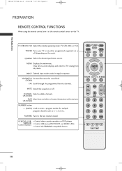
... ENTER RETURN AV MODE FAV VOL MUTE 12 P CH A G E 3 456 789 0 FLASHBK 10 TV/STB/DVD/VCR Select the remote operating mode: TV, STB, DVD, or VCR. CHANNEL Select available channels. TV POWER DVD STB VCR Q. POWER Turns your TV or any menu. Control USB menu (PHOTO LIST and MUSIC LIST.) Control the SIMPLINK... Page 10 PREPARATION PREPARATION REMOTE CONTROL FUNCTIONS When using the remote control, aim it at the remote control sensor on -screen displays and return to TV viewing from one full set of screen information to the next one.
... ENTER RETURN AV MODE FAV VOL MUTE 12 P CH A G E 3 456 789 0 FLASHBK 10 TV/STB/DVD/VCR Select the remote operating mode: TV, STB, DVD, or VCR. CHANNEL Select available channels. TV POWER DVD STB VCR Q. POWER Turns your TV or any menu. Control USB menu (PHOTO LIST and MUSIC LIST.) Control the SIMPLINK... Page 10 PREPARATION PREPARATION REMOTE CONTROL FUNCTIONS When using the remote control, aim it at the remote control sensor on -screen displays and return to TV viewing from one full set of screen information to the next one.

Owners Manual
Page 11
... the battery compartment cover on -screen menus and adjust the system settings to your preference. (Up/Down/Left Right/ENTER) RETURN Allows the user to TV. When you select and set images and sounds. AV MODE It helps you toggle this button, the SIMPLINK menu appears at the screen. I Close cover...
... the battery compartment cover on -screen menus and adjust the system settings to your preference. (Up/Down/Left Right/ENTER) RETURN Allows the user to TV. When you select and set images and sounds. AV MODE It helps you toggle this button, the SIMPLINK menu appears at the screen. I Close cover...

Owners Manual
Page 12
... bolts securely using the holes in the back of the TV. 3 Assemble the TV as shown. 2 Assemble the parts of the STAND BODY with COVER BASE of the TV. 12 Only 32/37/42LG30, 37/42LG50, 32/42LG70 1 Carefully place the TV screen side down on a cushioned surface to protect the... from damage. PREPARATION 2 Assemble the TV as shown. 4 Fix the 4 bolts securely using the holes in the back of the TV. MFL34797048-en-4 3/18/08 7:27 PM Page 12 PREPARATION STAND INSTALLATION I Image shown may differ from your TV Only 42PG25 1 Carefully place the TV screen side down on a cushioned surface...
... bolts securely using the holes in the back of the TV. 3 Assemble the TV as shown. 2 Assemble the parts of the STAND BODY with COVER BASE of the TV. 12 Only 32/37/42LG30, 37/42LG50, 32/42LG70 1 Carefully place the TV screen side down on a cushioned surface to protect the... from damage. PREPARATION 2 Assemble the TV as shown. 4 Fix the 4 bolts securely using the holes in the back of the TV. MFL34797048-en-4 3/18/08 7:27 PM Page 12 PREPARATION STAND INSTALLATION I Image shown may differ from your TV Only 42PG25 1 Carefully place the TV screen side down on a cushioned surface...

Owners Manual
Page 13
MFL34797048-en-4 3/18/08 7:27 PM Page 13 PREPARATION Only 32/37/42LG60 1 Carefully place the TV screen side down on a cushioned surface to protect the screen from damage. 2 Assemble the parts of the STAND BODY with COVER BASE of the TV. 32LG60 37LG60 42LG60 STAND BODY STAND BODY (M4x16) STAND BODY COVER BASE COVER BASE COVER BASE 3 Assemble the TV as shown. 4 Fix the 4 bolts securely using the holes in the back of the TV. (M4x20) 13
MFL34797048-en-4 3/18/08 7:27 PM Page 13 PREPARATION Only 32/37/42LG60 1 Carefully place the TV screen side down on a cushioned surface to protect the screen from damage. 2 Assemble the parts of the STAND BODY with COVER BASE of the TV. 32LG60 37LG60 42LG60 STAND BODY STAND BODY (M4x16) STAND BODY COVER BASE COVER BASE COVER BASE 3 Assemble the TV as shown. 4 Fix the 4 bolts securely using the holes in the back of the TV. (M4x20) 13

Owners Manual
Page 14
...the EXTERNAL EQUIPMENT SETUP section. 2 Install the CABLE MANAGEMENT CLIP as necessary. CABLE HOLDER CABLE MANAGEMENT CLIP How to remove the CABLE MANAGEMENT CLIP 42PG25 G First, press the cable management. Hold the CABLE MANAGEMENT CLIP with both hands and pull it upward. 50PG25, 50/60PG60 G Hold the ...CABLE MANAGEMENT CLIP with both hands and pull it as shown and bundle the cables. Plasma TV Model 1 Connect the cables as shown. MFL34797048-en-4 3/18/08 7:27 PM Page 14 PREPARATION PREPARATION CABLE MANAGEMENT I Here shown may be ...
...the EXTERNAL EQUIPMENT SETUP section. 2 Install the CABLE MANAGEMENT CLIP as necessary. CABLE HOLDER CABLE MANAGEMENT CLIP How to remove the CABLE MANAGEMENT CLIP 42PG25 G First, press the cable management. Hold the CABLE MANAGEMENT CLIP with both hands and pull it upward. 50PG25, 50/60PG60 G Hold the ...CABLE MANAGEMENT CLIP with both hands and pull it as shown and bundle the cables. Plasma TV Model 1 Connect the cables as shown. MFL34797048-en-4 3/18/08 7:27 PM Page 14 PREPARATION PREPARATION CABLE MANAGEMENT I Here shown may be ...

Owners Manual
Page 15
... closed. 2 Connect the cables as shown. Turn the CABLE MANAGEMENT CLIP as necessary. To connect additional equipment, see the EXTERNAL EQUIPMENT SETUP section. 32/37/42/47/52LG60 1 Align the hole with the tab on the CABLE MANAGEMENT CLIP. Note: This cable management can be broken by excessive pressure. 2 Install the... MANAGEMENT CLIP as necessary. To connect additional equipment, see the EXTERNAL EQUIPMENT SETUP section. 15 PREPARATION MFL34797048-en-4 3/18/08 7:27 PM Page 15 LCD TV Model 32/37/42LG30, 37/42/47/52LG50, 32/42/47/52LG70 1 Connect the cables as shown.
... closed. 2 Connect the cables as shown. Turn the CABLE MANAGEMENT CLIP as necessary. To connect additional equipment, see the EXTERNAL EQUIPMENT SETUP section. 32/37/42/47/52LG60 1 Align the hole with the tab on the CABLE MANAGEMENT CLIP. Note: This cable management can be broken by excessive pressure. 2 Install the... MANAGEMENT CLIP as necessary. To connect additional equipment, see the EXTERNAL EQUIPMENT SETUP section. 15 PREPARATION MFL34797048-en-4 3/18/08 7:27 PM Page 15 LCD TV Model 32/37/42LG30, 37/42/47/52LG50, 32/42/47/52LG70 1 Connect the cables as shown.

Owners Manual
Page 16
...degrees to the left or right direction by following the clearance recommendations. Tipping, shaking, or rocking the machine may differ from falling over, the TV should be pulled in a forward/backward direction, potentially causing injury or damaging the product. MFL34797048-en-4 3/18/08 7:27 PM Page 16... PREPARATION DESKTOP PEDESTAL INSTALLATION I Image shown may cause injury. 16 SWIVEL STAND After installing the TV, you can adjust the TV set manually to suit your TV. For proper ventilation, allow a clearance of the product) Desk WARNING G To prevent...
...degrees to the left or right direction by following the clearance recommendations. Tipping, shaking, or rocking the machine may differ from falling over, the TV should be pulled in a forward/backward direction, potentially causing injury or damaging the product. MFL34797048-en-4 3/18/08 7:27 PM Page 16... PREPARATION DESKTOP PEDESTAL INSTALLATION I Image shown may cause injury. 16 SWIVEL STAND After installing the TV, you can adjust the TV set manually to suit your TV. For proper ventilation, allow a clearance of the product) Desk WARNING G To prevent...

Owners Manual
Page 17
Plasma TV Models 400 mm (Except 60PG60: 600 mm) 400 mm R R R LCD TV Models 32/37/42LG30, 37/42/47/52LG50, 32/42/47/52LG70 200 mm (Except 52LG50/70: 800 mm) ( ) 32LG30/70: 100 mm 37LG30/50: 200 mm 42LG30/50/70: 200 mm 47LG50/70: 200 mm 52LG50/70: 400 mm 32/37/42/47... mounting bracket of the TV. MFL34797048-en-4 3/18/08 7:27 PM Page 17 PREPARATION VESA WALL MOUNTING This TV accepts VESA FDMI compliant mounts via the four screw holes on the wall mount used. NOTE G Screw length needed depends on the back of LG brand when mounting the TV to the instructions included with...
Plasma TV Models 400 mm (Except 60PG60: 600 mm) 400 mm R R R LCD TV Models 32/37/42LG30, 37/42/47/52LG50, 32/42/47/52LG70 200 mm (Except 52LG50/70: 800 mm) ( ) 32LG30/70: 100 mm 37LG30/50: 200 mm 42LG30/50/70: 200 mm 47LG50/70: 200 mm 52LG50/70: 400 mm 32/37/42/47... mounting bracket of the TV. MFL34797048-en-4 3/18/08 7:27 PM Page 17 PREPARATION VESA WALL MOUNTING This TV accepts VESA FDMI compliant mounts via the four screw holes on the wall mount used. NOTE G Screw length needed depends on the back of LG brand when mounting the TV to the instructions included with...

Owners Manual
Page 18
Plasma TV Models LCD TV Models After removing the protection paper from your TV. After removing the stand, install the included protection cover over the hole for the stand. Insert the PROTECTION COVER into the TV until clicking sound. PREPARATION MFL34797048-en-4 3/18/08 7:27 PM Page 18 PREPARATION PROTECTION COVER I Image shown may differ from the protection cover, adhere it to the TV as shown. 18 You can remove the stand before installing the TV on a wall mount by performing the previous stand instructions in reverse.
Plasma TV Models LCD TV Models After removing the protection paper from your TV. After removing the stand, install the included protection cover over the hole for the stand. Insert the PROTECTION COVER into the TV until clicking sound. PREPARATION MFL34797048-en-4 3/18/08 7:27 PM Page 18 PREPARATION PROTECTION COVER I Image shown may differ from the protection cover, adhere it to the TV as shown. 18 You can remove the stand before installing the TV on a wall mount by performing the previous stand instructions in reverse.

Owners Manual
Page 19
Caution: Please make sure that the height of the bracket on the wall and the one on or hang from the TV. I You should purchase necessary components to prevent TV from your product has the bolts in the eye-bolts position before inserting the eye-bolts, loosen the bolts. * Insert the eye-...bolts or TV brackets/bolts and tighten them securely in a forward direction, potentially causing injury or damaging the product. Secure the wall brackets with the bolts (not provided...
Caution: Please make sure that the height of the bracket on the wall and the one on or hang from the TV. I You should purchase necessary components to prevent TV from your product has the bolts in the eye-bolts position before inserting the eye-bolts, loosen the bolts. * Insert the eye-...bolts or TV brackets/bolts and tighten them securely in a forward direction, potentially causing injury or damaging the product. Secure the wall brackets with the bolts (not provided...

Owners Manual
Page 20
...-en-4 3/18/08 7:27 PM Page 20 PREPARATION PREPARATION I To prevent damage do not connect to be split for two TV's, install a 2-Way Signal Splitter. Cable Cable TV Wall Jack RF Coaxial Wire (75 ohm) ANTENNA/ CABLE IN R I If the antenna is not installed properly, contact your... adjust antenna direction if needed. Antenna (Analog or Digital) Wall Antenna Socket or Outdoor Antenna without a Cable Box Connection. NOTE G The TV will let you know when the analog, cable, and digital channel scans are made between the devices. Wall Antenna Socket Multi-family Dwellings/Apartments ...
...-en-4 3/18/08 7:27 PM Page 20 PREPARATION PREPARATION I To prevent damage do not connect to be split for two TV's, install a 2-Way Signal Splitter. Cable Cable TV Wall Jack RF Coaxial Wire (75 ohm) ANTENNA/ CABLE IN R I If the antenna is not installed properly, contact your... adjust antenna direction if needed. Antenna (Analog or Digital) Wall Antenna Socket or Outdoor Antenna without a Cable Box Connection. NOTE G The TV will let you know when the analog, cable, and digital channel scans are made between the devices. Wall Antenna Socket Multi-family Dwellings/Apartments ...

Owners Manual
Page 21
... settop box to the COMPONENT IN VIDEO 1 jacks on the remote control. I If connected to COMPONENT IN2 input, select the Component 2 input source on the TV. 2. Match the jack colors (Y = green, PB = blue, and PR = red). 2 Connect the audio output of EXTERNAL EQUIPMENT SETUP mainly use I ...set -top box to the COMPONENT IN AUDIO 1 jacks on the TV. 1 2 RGB IN DIGI RGB(PC) AUDIO REMOTE (RGB/DVI) CONTROL IN OPT 2 Y 1 PB PR L R VIDEO AUDIO COMPONENT IN RS-232 (CONTROL & S-VIDEO i.e) 37/42/47/52LG50 Supported Resolutions Signal 480i 480p 720p 1080i 1080p Component Yes ...
... settop box to the COMPONENT IN VIDEO 1 jacks on the remote control. I If connected to COMPONENT IN2 input, select the Component 2 input source on the TV. 2. Match the jack colors (Y = green, PB = blue, and PR = red). 2 Connect the audio output of EXTERNAL EQUIPMENT SETUP mainly use I ...set -top box to the COMPONENT IN AUDIO 1 jacks on the TV. 1 2 RGB IN DIGI RGB(PC) AUDIO REMOTE (RGB/DVI) CONTROL IN OPT 2 Y 1 PB PR L R VIDEO AUDIO COMPONENT IN RS-232 (CONTROL & S-VIDEO i.e) 37/42/47/52LG50 Supported Resolutions Signal 480i 480p 720p 1080i 1080p Component Yes ...

