Owner's Manual (English)
Page 2
...-resolution digital television broadcast and playback system composed of digital television, HDTV formats include 1080i and 720p resolutions. LG TV with one remote control. It has three HDMI ports that connect audio and video devices with this logo can play MP3 music from a MP3 player, such as iPOD, and JPEG images from SRS Labs, Inc. High-definition television. A subset of roughly a million or more pixels, 16:9 aspect-ratio screens, and AC3 digital audio. LG...
...-resolution digital television broadcast and playback system composed of digital television, HDTV formats include 1080i and 720p resolutions. LG TV with one remote control. It has three HDMI ports that connect audio and video devices with this logo can play MP3 music from a MP3 player, such as iPOD, and JPEG images from SRS Labs, Inc. High-definition television. A subset of roughly a million or more pixels, 16:9 aspect-ratio screens, and AC3 digital audio. LG...
Owner's Manual (English)
Page 3
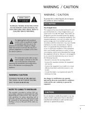
.... Connect the equipment to an outlet on , the user is provided to call the CATV system installer's attention to persons. NOTE TO CABLE/TV INSTALLER This reminder is encouraged to try to correct the interference by the party responsible for a Class B digital device, pursuant to Part 15 of electric shock to Article 820-40 of important operating and maintenance (servicing) instructions...
.... Connect the equipment to an outlet on , the user is provided to call the CATV system installer's attention to persons. NOTE TO CABLE/TV INSTALLER This reminder is encouraged to try to correct the interference by the party responsible for a Class B digital device, pursuant to Part 15 of electric shock to Article 820-40 of important operating and maintenance (servicing) instructions...

Owner's Manual (English)
Page 6
... Installation 16 Vesa Wall Mounting 16 Antenna or Cable Connection 17 EXTERNAL EQUIPMENT SETUP HD Receiver Setup 18 DVD Setup 21 VCR Setup 23 Other A/V Source Setup 25 PC Setup 26 USB In Setup 32 Audio Out Setup 33 WATCHING TV / CHANNEL CONTROL Remote Control Functions 34 Turning on TV 36 Channel Selection 37 Volume Adjustment 38 On-Screen Menus Selection 39 Channel Setup - Picture Mode - Color Tone - TruM 62 Picture Reset 63 SOUND & LANGUAGE CONTROL Auto Volume Leveler ( Auto Volume 64 Preset Sound Settings( Sound Mode 65 Sound Setting Adjustment - Analog Broadcasting...
... Installation 16 Vesa Wall Mounting 16 Antenna or Cable Connection 17 EXTERNAL EQUIPMENT SETUP HD Receiver Setup 18 DVD Setup 21 VCR Setup 23 Other A/V Source Setup 25 PC Setup 26 USB In Setup 32 Audio Out Setup 33 WATCHING TV / CHANNEL CONTROL Remote Control Functions 34 Turning on TV 36 Channel Selection 37 Volume Adjustment 38 On-Screen Menus Selection 39 Channel Setup - Picture Mode - Color Tone - TruM 62 Picture Reset 63 SOUND & LANGUAGE CONTROL Auto Volume Leveler ( Auto Volume 64 Preset Sound Settings( Sound Mode 65 Sound Setting Adjustment - Analog Broadcasting...

Owner's Manual (English)
Page 13
...COMPONENT IN Connect a component video/audio device to the appropriate input port. Note: In standby mode, these jacks. RGB(PC) AUDIO (RGB/DVI) Connect the monitor output from a PC to these jacks. AV (Audio/Video) IN 1 Connect audio/video output from an S-VIDEO device. Power Cord Socket For operation with a DVI to 1, 2 or 3. RS-232C IN (CONTROL & SERVICE) PORT Connect to these ports do not work. DIGITAL AUDIO OUT Connect digital audio to various types of equipment. Connect cable signals to operate the TV on a PC. REMOTE CONTROL PORT Connect your wired remote control...
...COMPONENT IN Connect a component video/audio device to the appropriate input port. Note: In standby mode, these jacks. RGB(PC) AUDIO (RGB/DVI) Connect the monitor output from a PC to these jacks. AV (Audio/Video) IN 1 Connect audio/video output from an S-VIDEO device. Power Cord Socket For operation with a DVI to 1, 2 or 3. RS-232C IN (CONTROL & SERVICE) PORT Connect to these ports do not work. DIGITAL AUDIO OUT Connect digital audio to various types of equipment. Connect cable signals to operate the TV on a PC. REMOTE CONTROL PORT Connect your wired remote control...

Owner's Manual (English)
Page 20
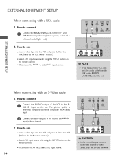
... colors (Y = green, PB = blue, and PR = red). 2 Connect the audio output of the digital set . How to connect 1 Connect the video outputs (Y, PB, PR) of the digital set-top box to the COMPONENT IN VIDEO 1 jacks on the set top box to the COMPONENT IN AUDIO 1 jacks on the remote control. This TV supports HDCP (High-bandwidth Digital Contents Protection) protocol for the digital set . EXTERNAL EQUIPMENT SETUP EXTERNAL EQUIPMENT SETUP HD RECEIVER SETUP This TV can receive Digital Over-the-air/Cable signals without an external digital set -top box or other digital external...
... colors (Y = green, PB = blue, and PR = red). 2 Connect the audio output of the digital set . How to connect 1 Connect the video outputs (Y, PB, PR) of the digital set-top box to the COMPONENT IN VIDEO 1 jacks on the set top box to the COMPONENT IN AUDIO 1 jacks on the remote control. This TV supports HDCP (High-bandwidth Digital Contents Protection) protocol for the digital set . EXTERNAL EQUIPMENT SETUP EXTERNAL EQUIPMENT SETUP HD RECEIVER SETUP This TV can receive Digital Over-the-air/Cable signals without an external digital set -top box or other digital external...

Owner's Manual (English)
Page 21
How to use I If the digital set-top box player does not support Auto HDMI, you need to the AUDIO (RGB/DVI) jack on the set the output resolution appropriately. I Turn on the remote control. RGB 1 2 When connecting HDMI cable 1. EXTERNAL EQUIPMENT SETUP When connecting D-sub 15pin cable 1. I Select HDMI1, HDMI2 or HDMI3 input source with using the INPUT button on the remote control. How to connect 1 Connect the digital set-top box to the owner's manual for the digital set-top box.) I Select RGB-PC input source with using the INPUT button on the PC...
How to use I If the digital set-top box player does not support Auto HDMI, you need to the AUDIO (RGB/DVI) jack on the set the output resolution appropriately. I Turn on the remote control. RGB 1 2 When connecting HDMI cable 1. EXTERNAL EQUIPMENT SETUP When connecting D-sub 15pin cable 1. I Select HDMI1, HDMI2 or HDMI3 input source with using the INPUT button on the remote control. How to connect 1 Connect the digital set-top box to the owner's manual for the digital set-top box.) I Select RGB-PC input source with using the INPUT button on the PC...

Owner's Manual (English)
Page 22
How to use I Turn on the digital set-top box. (Refer to the owner's manual for the digital set-top box.) I Select HDMI1, HDMI2 or HDMI3 input source with using the INPUT button on the set -top box to the AUDIO(RGB/DVI) jack on the remote control. 20 How to connect 1 Connect the DVI output of the digital set-top box to DVI cable RGB 3 EXTERNAL EQUIPMENT SETUP 2 1 DVI-DTV OUTPUT L R 1. EXTERNAL EQUIPMENT SETUP When connecting HDMI to the HDMI/DVI IN1, 2 or 3 jack on the set. 2 Connect the audio output of the digital set . 2.
How to use I Turn on the digital set-top box. (Refer to the owner's manual for the digital set-top box.) I Select HDMI1, HDMI2 or HDMI3 input source with using the INPUT button on the set -top box to the AUDIO(RGB/DVI) jack on the remote control. 20 How to connect 1 Connect the DVI output of the digital set-top box to DVI cable RGB 3 EXTERNAL EQUIPMENT SETUP 2 1 DVI-DTV OUTPUT L R 1. EXTERNAL EQUIPMENT SETUP When connecting HDMI to the HDMI/DVI IN1, 2 or 3 jack on the set. 2 Connect the audio output of the digital set . 2.

Owner's Manual (English)
Page 23
... colors (Y = green, PB = blue, and PR = red). 2 Connect the audio outputs of the DVD to the COMPONENT IN VIDEO1 jacks on the set . tions. EXTERNAL EQUIPMENT SETUP DVD SETUP When connecting Component cable 1. How to connect 1 Connect the video outputs (Y, PB, PR) of the DVD to COMPONENT IN 2 input, select COM- I If connected to the COMPONENT IN AUDIO1 jacks on the set . 2. Component ports on the TV Y PB PR Video output ports on the remote control. How to use I Refer to the component input ports as shown below. I Turn...
... colors (Y = green, PB = blue, and PR = red). 2 Connect the audio outputs of the DVD to the COMPONENT IN VIDEO1 jacks on the set . tions. EXTERNAL EQUIPMENT SETUP DVD SETUP When connecting Component cable 1. How to connect 1 Connect the video outputs (Y, PB, PR) of the DVD to COMPONENT IN 2 input, select COM- I If connected to the COMPONENT IN AUDIO1 jacks on the set . 2. Component ports on the TV Y PB PR Video output ports on the remote control. How to use I Refer to the component input ports as shown below. I Turn...

Owner's Manual (English)
Page 24
... 2 or 3 jack on the set the output resolution appropriately. 22 1 HDMI-DVD OUTPUT I Turn on the remote control. I If the DVD does not support Auto HDMI, you need to the AUDIO input jacks on the remote control. S-VIDEO AUDIO L R 1 2 EXTERNAL EQUIPMENT SETUP When connecting HDMI cable 1. EXTERNAL EQUIPMENT SETUP When connecting with using the INPUT button on the set. 2. How to the DVD player's manual for operating instructions. How to connect 1 Connect the S-VIDEO output of the DVD to the S-VIDEO input on the set. 2 Connect the audio outputs of the DVD to AV IN...
... 2 or 3 jack on the set the output resolution appropriately. 22 1 HDMI-DVD OUTPUT I Turn on the remote control. I If the DVD does not support Auto HDMI, you need to the AUDIO input jacks on the remote control. S-VIDEO AUDIO L R 1 2 EXTERNAL EQUIPMENT SETUP When connecting HDMI cable 1. EXTERNAL EQUIPMENT SETUP When connecting with using the INPUT button on the set. 2. How to the DVD player's manual for operating instructions. How to connect 1 Connect the S-VIDEO output of the DVD to the S-VIDEO input on the set. 2 Connect the audio outputs of the DVD to AV IN...
Owner's Manual (English)
Page 26
... use I D E O input on the set . VIDEO L R S-VIDEO ANT IN ANTENNA/ OUTPUT ANT OUT SWITCH CABLE IN 1 NOTE If you connect both Video and the S-Video cables, only the S-Video will work. Match the jack colors(Video = yellow, Audio Left = white,and Audio Right = red) 2. compared to normal composite (RCA cable) input. 2 Connect the audio outputs of the VCR to the VCR owner's manual.) I Select AV1 input source with using the INPUT button on the remote control. How to use I Insert a video tape into the VCR and press PLAY...
... use I D E O input on the set . VIDEO L R S-VIDEO ANT IN ANTENNA/ OUTPUT ANT OUT SWITCH CABLE IN 1 NOTE If you connect both Video and the S-Video cables, only the S-Video will work. Match the jack colors(Video = yellow, Audio Left = white,and Audio Right = red) 2. compared to normal composite (RCA cable) input. 2 Connect the audio outputs of the VCR to the VCR owner's manual.) I Select AV1 input source with using the INPUT button on the remote control. How to use I Insert a video tape into the VCR and press PLAY...
Owner's Manual (English)
Page 28
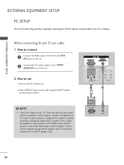
... the remote control. When connecting D-sub 15 pin cable 1. How to connect 1 Connect the RGB output of the PC graphic card. RGB 1 2 NOTE G Check the image on the PC and the set . 2. RGB OUTPUT AUDIO 26 If the refresh rate of the PC graphic card can not be noise associated with using the INPUT button on the VIDEO menu until the picture is present, change the PC output...
... the remote control. When connecting D-sub 15 pin cable 1. How to connect 1 Connect the RGB output of the PC graphic card. RGB 1 2 NOTE G Check the image on the PC and the set . 2. RGB OUTPUT AUDIO 26 If the refresh rate of the PC graphic card can not be noise associated with using the INPUT button on the VIDEO menu until the picture is present, change the PC output...
Owner's Manual (English)
Page 29
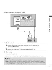
... remote control. To get the best picture quality, adjust the output resolution of the PC to the HDMI/DVI IN1, 2 or 3 jack on the set. (Use the HDMI to DVI cable) 2 Connect the PC audio output to use I Turn on the PC and the set I Select HDMI1, HDMI2 or HDMI3 input source with using the INPUT button on the set the output resolution appropriately. G If the PC does not support Auto DVI, you need to 1920x1080, 60Hz.(32/37/42LB4D models...
... remote control. To get the best picture quality, adjust the output resolution of the PC to the HDMI/DVI IN1, 2 or 3 jack on the set. (Use the HDMI to DVI cable) 2 Connect the PC audio output to use I Turn on the PC and the set I Select HDMI1, HDMI2 or HDMI3 input source with using the INPUT button on the set the output resolution appropriately. G If the PC does not support Auto DVI, you need to 1920x1080, 60Hz.(32/37/42LB4D models...

Owner's Manual (English)
Page 37
... (Antenna, Cable, AV 1-2, Component 1-2, RGB-PC, HDMI1, HDMI2, HDMI3 input sources are linked automatically, only if these are connected ). MODE Select the remote operating mode: TV, DVD, VCR, AUDIO, or STB. * If the mode of program.G p. 65 SAP Select MTS sound: Mono, Stereo, and SAP analog mode. G p.49 USB EJECT Remove the USB device. G p.32 Remote control effective range 32/37/42LB4D 37/42/47/52LB5D R I Open the battery compartment cover on the mode. G p.73 Installing Batteries...
... (Antenna, Cable, AV 1-2, Component 1-2, RGB-PC, HDMI1, HDMI2, HDMI3 input sources are linked automatically, only if these are connected ). MODE Select the remote operating mode: TV, DVD, VCR, AUDIO, or STB. * If the mode of program.G p. 65 SAP Select MTS sound: Mono, Stereo, and SAP analog mode. G p.49 USB EJECT Remove the USB device. G p.32 Remote control effective range 32/37/42LB4D 37/42/47/52LB5D R I Open the battery compartment cover on the mode. G p.73 Installing Batteries...

Owner's Manual (English)
Page 42
... ANTENNA and CABLE. Manual Tuning BACK Channel Edit BACK C PICTURE SOUND SAP PICTURE SAP CC PICTURE SOUND CC MARK USB EJECT MARK USB EJECT MARK USB EJECT 2 Press the G button and then use D or E button to the AuFtoouTnudnCinhgannel(s): 16 screen. Selection ( G oDrTV C)hl.e2a3ds you to Auto Tuning menu if the Lock System is turned on the channel list. Run Auto Tuning again after any Antenna/Cable connection changes. A password is required to gain access to the Auto Tuning screen. TV INPUT STB MEDIA...
... ANTENNA and CABLE. Manual Tuning BACK Channel Edit BACK C PICTURE SOUND SAP PICTURE SAP CC PICTURE SOUND CC MARK USB EJECT MARK USB EJECT MARK USB EJECT 2 Press the G button and then use D or E button to the AuFtoouTnudnCinhgannel(s): 16 screen. Selection ( G oDrTV C)hl.e2a3ds you to Auto Tuning menu if the Lock System is turned on the channel list. Run Auto Tuning again after any Antenna/Cable connection changes. A password is required to gain access to the Auto Tuning screen. TV INPUT STB MEDIA...
Owner's Manual (English)
Page 45
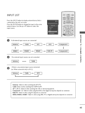
... external input sources are connected: Antenna Cable AV1 AV 2 Input List Antenna Cable AV 1 AV 2 Component1 E TV INPUT INPUT STB MEDIA HOST BRIGHT - AV 1, AV 2 : Select it when watching the CADTV/CATV. WATCHING TV / CHANNEL CONTROL INPUT LIST Press the INPUT button to display external device that is any external input source connected: (ex: When connected only to AV 2) Antenna Cable AV2 RGB-PC Component2 PICTURE SOUND SAP CC MARK USB EJECT Antenna : Select it when watching the DTV/TV. Use the D or E button to select the input source...
... external input sources are connected: Antenna Cable AV1 AV 2 Input List Antenna Cable AV 1 AV 2 Component1 E TV INPUT INPUT STB MEDIA HOST BRIGHT - AV 1, AV 2 : Select it when watching the CADTV/CATV. WATCHING TV / CHANNEL CONTROL INPUT LIST Press the INPUT button to display external device that is any external input source connected: (ex: When connected only to AV 2) Antenna Cable AV2 RGB-PC Component2 PICTURE SOUND SAP CC MARK USB EJECT Antenna : Select it when watching the DTV/TV. Use the D or E button to select the input source...
Owner's Manual (English)
Page 46
... MARK USB EJECT Language Input label SimpLink Key Lock Caption Set ID G Off On 5 Press EXIT button to return to TV viewing or press MENU button to return to the previous menu. G When you execute 'Photo List, Music List 'function during DVD playback included in the above method, connect the DIGITAL AUDIO OUT OPTICAL on the back of the TV to the DIGITAL AUDIO IN terminal on the remote control. NOTE G When operating the external...
... MARK USB EJECT Language Input label SimpLink Key Lock Caption Set ID G Off On 5 Press EXIT button to return to TV viewing or press MENU button to return to the previous menu. G When you execute 'Photo List, Music List 'function during DVD playback included in the above method, connect the DIGITAL AUDIO OUT OPTICAL on the back of the TV to the DIGITAL AUDIO IN terminal on the remote control. NOTE G When operating the external...

Owner's Manual (English)
Page 84
... all program viewing for -TV movies : I TV-G (General audience) I TV-PG (Parental guidance suggested) I TV-14 (Parents strongly cautioned) I TV-MA (Mature audience only) I TV-Y (All children) I TV-Y7 (Children 7 years older) PARENTAL CONTROL / RATING SET PASSWORD & LOCK SYSTEM TV INPUT TV INPUT Setting up your Password STB MEDIA HOST STB MEDIA HOST Set up with the initial password "0-0-0-0". Then, press the G button. Enter Password 82 BACK PICTURE SOUND SAP CC BACK TV INPUT STB MEDIA HOST BRIGHT - MENU BRIGHT + TIMER RATIO SIMPLINK BACK The default setting...
... all program viewing for -TV movies : I TV-G (General audience) I TV-PG (Parental guidance suggested) I TV-14 (Parents strongly cautioned) I TV-MA (Mature audience only) I TV-Y (All children) I TV-Y7 (Children 7 years older) PARENTAL CONTROL / RATING SET PASSWORD & LOCK SYSTEM TV INPUT TV INPUT Setting up your Password STB MEDIA HOST STB MEDIA HOST Set up with the initial password "0-0-0-0". Then, press the G button. Enter Password 82 BACK PICTURE SOUND SAP CC BACK TV INPUT STB MEDIA HOST BRIGHT - MENU BRIGHT + TIMER RATIO SIMPLINK BACK The default setting...

Owner's Manual (English)
Page 96
... be programmed to operate most remote-controllable devices. APPENDIX PROGRAMMING THE REMOTE CONTROL The provided universal remote control can operate each device without programming, turn on the device (such as a VCR) and press the corresponding mode button on the mode button will be programmed to repeat from step 2. 3 Enter the appropriate code from the code table on the following pages. The programming procedures are explained below. 2 Press the MENU and MUTE button continuously at a time...
... be programmed to operate most remote-controllable devices. APPENDIX PROGRAMMING THE REMOTE CONTROL The provided universal remote control can operate each device without programming, turn on the device (such as a VCR) and press the corresponding mode button on the mode button will be programmed to repeat from step 2. 3 Enter the appropriate code from the code table on the following pages. The programming procedures are explained below. 2 Press the MENU and MUTE button continuously at a time...
Owner's Manual (English)
Page 105
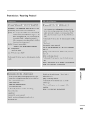
...] : use the large character *in Setup menu. Ex) ka 01 01(CR)(LF)a 01 OK01x(CR)(LF) Error Acknowledgement [Command2][ ][Set ID][ ][NG][Data][x] The TV transmits ACK (acknowledgement) based on this format when receiving normal data. Transmit 'FF' data to choose desired TV ID number in this model, TV will send the echo, CR, LF with ack message. Data1: Illegal Code Data2: Not supported...
...] : use the large character *in Setup menu. Ex) ka 01 01(CR)(LF)a 01 OK01x(CR)(LF) Error Acknowledgement [Command2][ ][Set ID][ ][NG][Data][x] The TV transmits ACK (acknowledgement) based on this format when receiving normal data. Transmit 'FF' data to choose desired TV ID number in this model, TV will send the echo, CR, LF with ack message. Data1: Illegal Code Data2: Not supported...
Owner's Manual (English)
Page 109
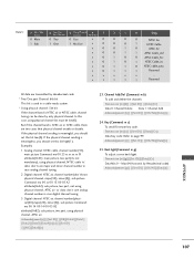
...:64(*transmit by only physical channel. Reserved All data are two cases that physical channel enable or disable. If the physical channel sending is ATSC air or ATSC cable, there are transmitted by Hexadecimal code * Two/One part Channel: 6th bit This bit is used in case analog channel tuning. 2. Example) 1. Acknowledgement [c][ ][Set ID][ ][OK/NG][Data][x] 25. Back light(Command: m g) To adjust screen back light.
...:64(*transmit by only physical channel. Reserved All data are two cases that physical channel enable or disable. If the physical channel sending is ATSC air or ATSC cable, there are transmitted by Hexadecimal code * Two/One part Channel: 6th bit This bit is used in case analog channel tuning. 2. Example) 1. Acknowledgement [c][ ][Set ID][ ][OK/NG][Data][x] 25. Back light(Command: m g) To adjust screen back light.


