Owners Manual
Page 2
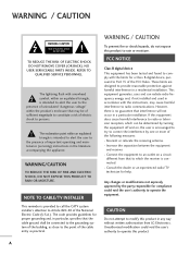
...digital device, pursuant to Part 15 of the FCC Rules. The lightning flash with the instructions, may be of sufficient magnitude to constitute a risk of electric shock to the point of the building, as close to persons. This equipment generates, uses and can be connected to the grounding system of the cable...relocate the receiving antenna. - REFER TO QUALIFIED SERVICE PERSONNEL. The exclamation point within the product's enclosure that the cable ground shall be determined by one or more of the National Electric Code (U.S.A.). Consult the dealer or an experienced radio/TV technician ...
...digital device, pursuant to Part 15 of the FCC Rules. The lightning flash with the instructions, may be of sufficient magnitude to constitute a risk of electric shock to the point of the building, as close to persons. This equipment generates, uses and can be connected to the grounding system of the cable...relocate the receiving antenna. - REFER TO QUALIFIED SERVICE PERSONNEL. The exclamation point within the product's enclosure that the cable ground shall be determined by one or more of the National Electric Code (U.S.A.). Consult the dealer or an experienced radio/TV technician ...
Owners Manual
Page 5
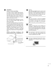
... other materials (e.g.) plastic while plugged in wire to an antenna discharge unit, size of grounding conductors, location of overhead power lines or other liquids directly on the TV as to prevent scratching. 20 ANTENNAS Outdoor antenna grounding If an outdoor antenna is proper ventilation. Be sure the antenna system is turned off, unplugged and all cables have been removed. Do not clean with...
... other materials (e.g.) plastic while plugged in wire to an antenna discharge unit, size of grounding conductors, location of overhead power lines or other liquids directly on the TV as to prevent scratching. 20 ANTENNAS Outdoor antenna grounding If an outdoor antenna is proper ventilation. Be sure the antenna system is turned off, unplugged and all cables have been removed. Do not clean with...
Owners Manual
Page 6
...) Mode only 70 Manual Configure 71 Selecting XGA Mode 72 Initializing (Reset to a Desk 18 VESA Wall Mounting 19 Desktop Pedestal Installation 19 Antenna or Cable Connection 20 EXTERNAL EQUIPMENT SETUP HD Receiver Setup 21 DVD Setup 24 VCR Setup 26 Other A/V Source Setup 28 Digital Audio Output 28 PC Setup 29 WATCHING TV / CHANNEL CONTROL Remote Control Functions 32 Turning On TV 34 Channel Selection 34 Volume Adjustment 34 On-Screen Menus Selection 35 Channel Setup 36 - Color Tone - User Mode 48 XD - User Mode 56 Balance Adjustment 57 TV Speakers On/Off Setup 58...
...) Mode only 70 Manual Configure 71 Selecting XGA Mode 72 Initializing (Reset to a Desk 18 VESA Wall Mounting 19 Desktop Pedestal Installation 19 Antenna or Cable Connection 20 EXTERNAL EQUIPMENT SETUP HD Receiver Setup 21 DVD Setup 24 VCR Setup 26 Other A/V Source Setup 28 Digital Audio Output 28 PC Setup 29 WATCHING TV / CHANNEL CONTROL Remote Control Functions 32 Turning On TV 34 Channel Selection 34 Volume Adjustment 34 On-Screen Menus Selection 35 Channel Setup 36 - Color Tone - User Mode 48 XD - User Mode 56 Balance Adjustment 57 TV Speakers On/Off Setup 58...
Owners Manual
Page 11
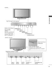
... is switched on . POWER Button INPUT Button MENU Button ENTER Button VOLUME Buttons CHANNEL Buttons 42PG60C, 42PG65C Stand (Only 42PG65C model) Remote Control Sensor POWER Button Power/Standby Indicator Illuminates red in standby mode. INPUT MENU ENTER VOL CH INPUT MENU ENTER VOL CH INPUT MENU ENTER VOL CH INPUT Button MENU Button ENTER Button VOLUME (-,+) Buttons CHANNEL (E, D) Buttons 9 INPUT MENU ENTER VOL CH Remote Control Sensor Power/Standby Indicator Illuminates red when the TV is sold, separately. INPUT ENTER Illuminates blue when the set...
... is switched on . POWER Button INPUT Button MENU Button ENTER Button VOLUME Buttons CHANNEL Buttons 42PG60C, 42PG65C Stand (Only 42PG65C model) Remote Control Sensor POWER Button Power/Standby Indicator Illuminates red in standby mode. INPUT MENU ENTER VOL CH INPUT MENU ENTER VOL CH INPUT MENU ENTER VOL CH INPUT Button MENU Button ENTER Button VOLUME (-,+) Buttons CHANNEL (E, D) Buttons 9 INPUT MENU ENTER VOL CH Remote Control Sensor Power/Standby Indicator Illuminates red when the TV is sold, separately. INPUT ENTER Illuminates blue when the set...
Owners Manual
Page 13
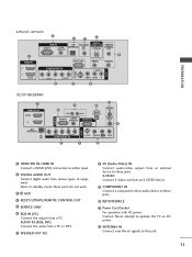
.... 7 SPEAKER OUT 8Ω 8 AV (Audio/Video) IN Connect audio/video output from a PC. Note: In standby mode, these ports do not work. 3 13 M.P.I 4 RESET/UPDATE/REMOTE CONTROL OUT 5 SERVICE ONLY 6 RGB IN (PC) Connect the output from an external device to these jacks. 10 RJP INTERFACE 11 Power Cord Socket For operation with AC power. S-VIDEO Connect S-Video out from various types of equipment. Caution: Never attempt to operate the TV on DC power. 12 ANTENNA IN Connect over-the air signals to...
.... 7 SPEAKER OUT 8Ω 8 AV (Audio/Video) IN Connect audio/video output from a PC. Note: In standby mode, these ports do not work. 3 13 M.P.I 4 RESET/UPDATE/REMOTE CONTROL OUT 5 SERVICE ONLY 6 RGB IN (PC) Connect the output from an external device to these jacks. 10 RJP INTERFACE 11 Power Cord Socket For operation with AC power. S-VIDEO Connect S-Video out from various types of equipment. Caution: Never attempt to operate the TV on DC power. 12 ANTENNA IN Connect over-the air signals to...
Owners Manual
Page 21
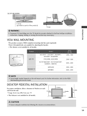
.... DESKTOP PEDESTAL INSTALLATION For proper ventilation, allow a clearance of the product) Desk WARNING G To prevent TV from falling over, the TV should be securely attached to the VESA Wall Mounting Instruction Guide. 32/37/42LG500H Stand PREPARATION 1-Screw (provided as parts of 4inches on the wall mount used. VESA WALL MOUNTING This product accepts a VESA-compliant mounting interface pad. (optional) There 4 threaded holes are available for attaching the bracket. ■ This...
.... DESKTOP PEDESTAL INSTALLATION For proper ventilation, allow a clearance of the product) Desk WARNING G To prevent TV from falling over, the TV should be securely attached to the VESA Wall Mounting Instruction Guide. 32/37/42LG500H Stand PREPARATION 1-Screw (provided as parts of 4inches on the wall mount used. VESA WALL MOUNTING This product accepts a VESA-compliant mounting interface pad. (optional) There 4 threaded holes are available for attaching the bracket. ■ This...
Owners Manual
Page 23
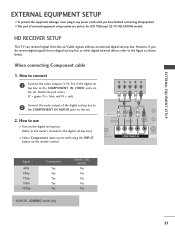
... plug in any power cords until you do receive digital signals from a digital set-top box or other digital external device, refer to the owner's manual for LCD TV(Except 32/37/42LG500H) models. HD RECEIVER SETUP This TV can receive Digital Over-the-air/Cable signals without an external digital set -top box.) ■ Select Component input source with using the INPUT button on the set. 2. How to connect 1 Connect the video outputs (Y, PB, PR) of the digital set top box to 2 the COMPONENT IN AUDIO jacks on the remote control. HDMI/DVI IN 1(DVI) 1 2 DIGITAL AUDIO OUT (OPTICAL...
... plug in any power cords until you do receive digital signals from a digital set-top box or other digital external device, refer to the owner's manual for LCD TV(Except 32/37/42LG500H) models. HD RECEIVER SETUP This TV can receive Digital Over-the-air/Cable signals without an external digital set -top box.) ■ Select Component input source with using the INPUT button on the set. 2. How to connect 1 Connect the video outputs (Y, PB, PR) of the digital set top box to 2 the COMPONENT IN AUDIO jacks on the remote control. HDMI/DVI IN 1(DVI) 1 2 DIGITAL AUDIO OUT (OPTICAL...
Owners Manual
Page 24
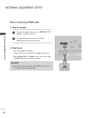
... source with using the INPUT button on the set. 2 No separated audio connection is necessary. How to use ■ Turn on the digital set-top box. ( ) (Refer to HDMI/DVI IN 1(DVI) or 2 jack on the remote control. How to connect 1 Connect the digital set-top box to the owner's manual for the digital set the output resolution appropriately. EXTERNAL EQUIPMENT SETUP EXTERNAL EQUIPMENT SETUP When connecting HDMI cable 1. HDMI/DVI IN 1(DVI) DIGITAL AUDIO OUT (OPTICAL) 2 M.P.I RJP INTERFACE 1 VIDEO AUDIO COMPONENT IN HDMI-DTV OUTPUT ( ) 22 HDMI supports both audio and video...
... source with using the INPUT button on the set. 2 No separated audio connection is necessary. How to use ■ Turn on the digital set-top box. ( ) (Refer to HDMI/DVI IN 1(DVI) or 2 jack on the remote control. How to connect 1 Connect the digital set-top box to the owner's manual for the digital set the output resolution appropriately. EXTERNAL EQUIPMENT SETUP EXTERNAL EQUIPMENT SETUP When connecting HDMI cable 1. HDMI/DVI IN 1(DVI) DIGITAL AUDIO OUT (OPTICAL) 2 M.P.I RJP INTERFACE 1 VIDEO AUDIO COMPONENT IN HDMI-DTV OUTPUT ( ) 22 HDMI supports both audio and video...
Owners Manual
Page 25
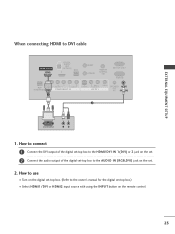
RESET UPDATE REMOTE CONTROL OUT SERVICE ONLY RGB IN RJP INTERFACE 1 VIDEO AUDIO COMPONENT IN S-VIDEO (MONO) AUDIO AV IN 1 VIDEO SPEAKER AUDIO OUT IN 8 (RGB, DVI) 2 DVI-DTV OUTPUT L R 1. EXTERNAL EQUIPMENT SETUP When connecting HDMI to the owner's manual for the digital set . 2. How to connect 1 Connect the DVI output of the digital set-top box to the HDMI/DVI IN 1(DVI) or 2 jack on the set. 2 Connect the audio output of the digital set-top box to the AUDIO IN (RGB,DVI) jack on the set -top...
RESET UPDATE REMOTE CONTROL OUT SERVICE ONLY RGB IN RJP INTERFACE 1 VIDEO AUDIO COMPONENT IN S-VIDEO (MONO) AUDIO AV IN 1 VIDEO SPEAKER AUDIO OUT IN 8 (RGB, DVI) 2 DVI-DTV OUTPUT L R 1. EXTERNAL EQUIPMENT SETUP When connecting HDMI to the owner's manual for the digital set . 2. How to connect 1 Connect the DVI output of the digital set-top box to the HDMI/DVI IN 1(DVI) or 2 jack on the set. 2 Connect the audio output of the digital set-top box to the AUDIO IN (RGB,DVI) jack on the set -top...

Owners Manual
Page 26
... set . 2. HDMI/DVI IN 1(DVI) 1 2 DIGITAL AUDIO OUT (OPTICAL) 2 M.P.I. ■ Select Component input source with using the INPUT button on DVD player Y Y PB PR PB PR B-Y R-Y Cb Cr Pb Pr 24 How to connect 1 Connect the video outputs (Y, PB, PR) of the DVD to the 2 COMPONENT IN AUDIO jacks on the set . Y PB PR L R Connect the audio outputs of the DVD to the DVD player's manual for operating instructions. Match the jack colors (Y = green, PB = blue, and PR = red). Component ports on the TV Y Y Video output ports Y on the remote control...
... set . 2. HDMI/DVI IN 1(DVI) 1 2 DIGITAL AUDIO OUT (OPTICAL) 2 M.P.I. ■ Select Component input source with using the INPUT button on DVD player Y Y PB PR PB PR B-Y R-Y Cb Cr Pb Pr 24 How to connect 1 Connect the video outputs (Y, PB, PR) of the DVD to the 2 COMPONENT IN AUDIO jacks on the set . Y PB PR L R Connect the audio outputs of the DVD to the DVD player's manual for operating instructions. Match the jack colors (Y = green, PB = blue, and PR = red). Component ports on the TV Y Y Video output ports Y on the remote control...

Owners Manual
Page 27
... 25 S-VIDEO AUDIO L R EXTERNAL EQUIPMENT SETUP 2 Connect the audio outputs of the DVD to set . 2. RJP INTERFACE VIDEO AUDIO COMPONENT IN 1 NOTE G If the device does not support Auto HDMI, you need to the AUDIO input jacks on the set . 2 No separated audio connection is necessary. How to connect 1 Connect the HDMI output of the DVD to use ■ Turn on the DVD player, insert a DVD. ■ Select A V 1 input source with an S-Video cable 1. When connecting with using the INPUT button on the set . How to the S -VIDEO input on the set the output resolution...
... 25 S-VIDEO AUDIO L R EXTERNAL EQUIPMENT SETUP 2 Connect the audio outputs of the DVD to set . 2. RJP INTERFACE VIDEO AUDIO COMPONENT IN 1 NOTE G If the device does not support Auto HDMI, you need to the AUDIO input jacks on the set . 2 No separated audio connection is necessary. How to connect 1 Connect the HDMI output of the DVD to use ■ Turn on the DVD player, insert a DVD. ■ Select A V 1 input source with an S-Video cable 1. When connecting with using the INPUT button on the set . How to the S -VIDEO input on the set the output resolution...

Owners Manual
Page 29
... S-VIDEO L R VIDEO EXTERNAL EQUIPMENT SETUP 1. NOTE G The picture quality is improved: compared to AV IN2, select A V 2 input source. ANT IN S-VIDEO L R VIDEO ANT OUT OUTPUT SWITCH 2 Connect the audio outputs of the VCR to both Video and the S-Video cables, only the S-Video will work. 27 How to AV IN2, select A V 2 input source. How to use ■ Insert a video tape into the VCR and press PLAY on the VCR. (Refer to the VCR owner's manual.) ■...
... S-VIDEO L R VIDEO EXTERNAL EQUIPMENT SETUP 1. NOTE G The picture quality is improved: compared to AV IN2, select A V 2 input source. ANT IN S-VIDEO L R VIDEO ANT OUT OUTPUT SWITCH 2 Connect the audio outputs of the VCR to both Video and the S-Video cables, only the S-Video will work. 27 How to AV IN2, select A V 2 input source. How to use ■ Insert a video tape into the VCR and press PLAY on the VCR. (Refer to the VCR owner's manual.) ■...

Owners Manual
Page 30
...RJP VIDEO AUDIO S-V NTERFACE COMPONENT IN 2 NOTE G When connecting with using the INPUT button on the remote control. ■ If connected to the digital audio (optical) input on the audio equipment. 3 Set the "TV Speaker option - How to connect 1 Connect one end of an optical cable to the TV Digital Audio (Optical) Output port. 2 Connect the other end of the optical cable to AV IN1 input, select A V 1 input source. ■ Operate the corresponding external equipment. Match the jack colors. (Video = yellow, Audio Left = white, and Audio Right = red) Camcorder Video Game Set...
...RJP VIDEO AUDIO S-V NTERFACE COMPONENT IN 2 NOTE G When connecting with using the INPUT button on the remote control. ■ If connected to the digital audio (optical) input on the audio equipment. 3 Set the "TV Speaker option - How to connect 1 Connect one end of an optical cable to the TV Digital Audio (Optical) Output port. 2 Connect the other end of the optical cable to AV IN1 input, select A V 1 input source. ■ Operate the corresponding external equipment. Match the jack colors. (Video = yellow, Audio Left = white, and Audio Right = red) Camcorder Video Game Set...

Owners Manual
Page 31
... RGB-PC input source with using the INPUT button on the remote control. 2 1 When connecting HDMI to use ■ Turn on the PC and the set 2 ■ Select HDMI1/DVI input source with using the INPUT button on the set . 2. How to DVI cable RGB OUTPUT AUDIO 1. DVI-PC OUTPUT AUDIO 29 When connecting D-sub 15pin cable 1. How to connect 1 Connect the DVI output of the PC to the RGB IN jack on the set. (MONO) AUDIO AV IN 1 VIDEO SPEAKER AUDIO OUT...
... RGB-PC input source with using the INPUT button on the remote control. 2 1 When connecting HDMI to use ■ Turn on the PC and the set 2 ■ Select HDMI1/DVI input source with using the INPUT button on the set . 2. How to DVI cable RGB OUTPUT AUDIO 1. DVI-PC OUTPUT AUDIO 29 When connecting D-sub 15pin cable 1. How to connect 1 Connect the DVI output of the PC to the RGB IN jack on the set. (MONO) AUDIO AV IN 1 VIDEO SPEAKER AUDIO OUT...
Owners Manual
Page 32
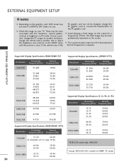
... mode. The fixed image may not work if a HDMI to another rate or adjust the brightness and contrast on the VIDEO menu until the picture is present, change the PC output to another resolution, change the PC graphic card or consult the manufacturer of the PC graphic card. EXTERNAL EQUIPMENT SETUP NOTES G Depending on the graphics card, DOS mode may become permanently imprinted on the screen...
... mode. The fixed image may not work if a HDMI to another rate or adjust the brightness and contrast on the VIDEO menu until the picture is present, change the PC output to another resolution, change the PC graphic card or consult the manufacturer of the PC graphic card. EXTERNAL EQUIPMENT SETUP NOTES G Depending on the graphics card, DOS mode may become permanently imprinted on the screen...

Owners Manual
Page 34
...CONTROL FUNCTIONS When using the remote control, aim it at the remote control sensor on screen. PIP Switches the sub picture Double Window or off , depending on the viewing EZ PIC environment. TV INPUT In AV 1-2, Component, RGB, HDMI1/DVI, and HDMI2 input sources, screen returns to the last channel viewed. control buttons NUMBER button - (DASH) Used to enter a program number for multiple program channels such as 2-1, 2-2, etc. G p.41 Selects the factory preset picture depend on mode. INPUT TV POWER MODE TV INPUT DVD MULTI VCR PIP PIP CH - External input modes...
...CONTROL FUNCTIONS When using the remote control, aim it at the remote control sensor on screen. PIP Switches the sub picture Double Window or off , depending on the viewing EZ PIC environment. TV INPUT In AV 1-2, Component, RGB, HDMI1/DVI, and HDMI2 input sources, screen returns to the last channel viewed. control buttons NUMBER button - (DASH) Used to enter a program number for multiple program channels such as 2-1, 2-2, etc. G p.41 Selects the factory preset picture depend on mode. INPUT TV POWER MODE TV INPUT DVD MULTI VCR PIP PIP CH - External input modes...
Owners Manual
Page 37
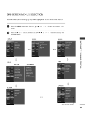
...menu. Manual config. or button to display the SETUP SETUP VIDEO AUDIO TIME OPTION SCREEN LOCK EZ Scan Manual Scan Channel Edit DTV Signal Channel Label VIDEO SETUP VIDEO AUDIO TIME OPTION SCREEN LOCK EZ Picture Color Temperature XD Advanced Reset AUDIO SETUP Audio Language VIDEO EZ SoundRite AUDIO EZ Sound TIME Balance 0 OPTION TV Speakers SCREEN LOCK WATCHING TV / CHANNEL CONTROL LOCK For USA SETUP VIDEO AUDIO TIME OPTION SCREEN LOCK Lock System Set Password Block Channel Movie Rating TV Rating-Children TV Rating-General Aux. XGA Mode Reset TIME SETUP VIDEO AUDIO...
...menu. Manual config. or button to display the SETUP SETUP VIDEO AUDIO TIME OPTION SCREEN LOCK EZ Scan Manual Scan Channel Edit DTV Signal Channel Label VIDEO SETUP VIDEO AUDIO TIME OPTION SCREEN LOCK EZ Picture Color Temperature XD Advanced Reset AUDIO SETUP Audio Language VIDEO EZ SoundRite AUDIO EZ Sound TIME Balance 0 OPTION TV Speakers SCREEN LOCK WATCHING TV / CHANNEL CONTROL LOCK For USA SETUP VIDEO AUDIO TIME OPTION SCREEN LOCK Lock System Set Password Block Channel Movie Rating TV Rating-Children TV Rating-General Aux. XGA Mode Reset TIME SETUP VIDEO AUDIO...
Owners Manual
Page 76
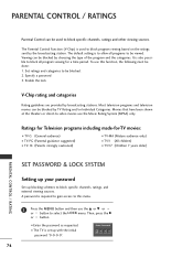
... or button to be viewed. Movies that have been shown at the theaters or direct-to block specific channels, ratings, and external viewing sources. The default setting is also possible to block all programs to select the LOCK menu. Most television programs and television movies can be blocked by broadcasting stations. PARENTAL CONTROL / RATINGS Parental Control can be used to allow all program viewing for -TV movies: ■ TV-G (General audience) ■ TV-PG (Parental guidance...
... or button to be viewed. Movies that have been shown at the theaters or direct-to block specific channels, ratings, and external viewing sources. The default setting is also possible to block all programs to select the LOCK menu. Most television programs and television movies can be blocked by broadcasting stations. PARENTAL CONTROL / RATINGS Parental Control can be used to allow all program viewing for -TV movies: ■ TV-G (General audience) ■ TV-PG (Parental guidance...

Owners Manual
Page 78
... channel numbers and a preview picture. 3 Use D E F G or button to select a channel and then use the D or E or or button to select O n or O f f on the each source. 4 Press EXIT or RETURN button to return to TV view- ing or press MENU button to return to the previous menu. Block Downloadable Rating 12 For USA SETUP VIDEO AUDIO TIME OPTION SCREEN LOCK Lock System Set Password Block Channel Movie Rating TV Rating-Children TV Rating-General Aux. PARENTAL CONTROL / RATING 1 After inputting the password, use...
... channel numbers and a preview picture. 3 Use D E F G or button to select a channel and then use the D or E or or button to select O n or O f f on the each source. 4 Press EXIT or RETURN button to return to TV view- ing or press MENU button to return to the previous menu. Block Downloadable Rating 12 For USA SETUP VIDEO AUDIO TIME OPTION SCREEN LOCK Lock System Set Password Block Channel Movie Rating TV Rating-Children TV Rating-General Aux. PARENTAL CONTROL / RATING 1 After inputting the password, use...
Owners Manual
Page 86
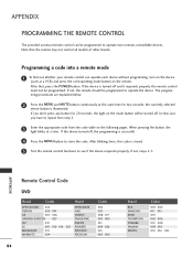
... the appropriate code from the code table on the remote. If the device turned off, the programming is turned off . If the device is successful. 4 Press the MENU button to see if the device responds properly. After blinking twice, this code is illuminated. The programming procedures are explained below. 2 Press the MENU and MUTE button continuously at a time. APPENDIX Remote Control Code DVD Brand Codes Brand APEX DIGITAL 022 DENON 020...
... the appropriate code from the code table on the remote. If the device turned off, the programming is turned off . If the device is successful. 4 Press the MENU button to see if the device responds properly. After blinking twice, this code is illuminated. The programming procedures are explained below. 2 Press the MENU and MUTE button continuously at a time. APPENDIX Remote Control Code DVD Brand Codes Brand APEX DIGITAL 022 DENON 020...


