
Service Manual
Page 1
website:http://biz.LGservice.com e-mail:http://www.LGEservice.com/techsup.html LCD TV SERVICE MANUAL CHASSIS : ML-051A MODEL : 32LX2R-TE CAUTION BEFORE SERVICING THE CHASSIS, READ THE SAFETY PRECAUTIONS IN THIS MANUAL.
website:http://biz.LGservice.com e-mail:http://www.LGEservice.com/techsup.html LCD TV SERVICE MANUAL CHASSIS : ML-051A MODEL : 32LX2R-TE CAUTION BEFORE SERVICING THE CHASSIS, READ THE SAFETY PRECAUTIONS IN THIS MANUAL.
Service Manual
Page 2
CONTENTS CONTENTS 2 PRODUCT SAFETY 3 SPECIFICATION 6 ADJUSTMENT INSTRUCTION 11 TROUBLE SHOOTING 15 BLOCK DIAGRAM 18 WIRING DIAGRAM 19 EXPLODED VIEW 20 EXPLODED VIEW PARTS LIST 21 REPLACEMENT PARTS LIST 22 SVC. SHEET -2-
CONTENTS CONTENTS 2 PRODUCT SAFETY 3 SPECIFICATION 6 ADJUSTMENT INSTRUCTION 11 TROUBLE SHOOTING 15 BLOCK DIAGRAM 18 WIRING DIAGRAM 19 EXPLODED VIEW 20 EXPLODED VIEW PARTS LIST 21 REPLACEMENT PARTS LIST 22 SVC. SHEET -2-
Service Manual
Page 3
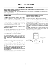
General Guidance An isolation Transformer should always be inadvertently introduced during the service operation. When replacing a high wattage resistor (Oxide Metal Film Resistor, over 1W), keep the resistor 10mm away from the AC power line. Place the AC switch in the on the exposed metallic parts of the cabinet, such as antennas, terminals, etc., to be between a known good earth ground (Water Pipe, Conduit, etc.) and the exposed metallic parts. Measure the AC voltage across the two AC plug prongs. These parts are identified by accidental shorts of a receiver whose chassis ...
General Guidance An isolation Transformer should always be inadvertently introduced during the service operation. When replacing a high wattage resistor (Oxide Metal Film Resistor, over 1W), keep the resistor 10mm away from the AC power line. Place the AC switch in the on the exposed metallic parts of the cabinet, such as antennas, terminals, etc., to be between a known good earth ground (Water Pipe, Conduit, etc.) and the exposed metallic parts. Measure the AC voltage across the two AC plug prongs. These parts are identified by accidental shorts of a receiver whose chassis ...
Service Manual
Page 4
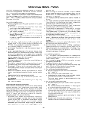
b. c. Do not test high voltage by this service manual, lubrication of 60 parts tin/40 parts lead. 3. Use with solder braid. Examples of typical ES devices are called Electrostatically Sensitive (ES) Devices. After removing an electrical assembly equipped with ES devices, place the assembly on a conductive surface such as aluminum foil, to install it. (Most replacement ES devices are ready to prevent electrostatic charge buildup or exposure of a replacement ES device, touch the protective material to damage ES devices. 5. Do not remove a replacement ES device from the ...
b. c. Do not test high voltage by this service manual, lubrication of 60 parts tin/40 parts lead. 3. Use with solder braid. Examples of typical ES devices are called Electrostatically Sensitive (ES) Devices. After removing an electrical assembly equipped with ES devices, place the assembly on a conductive surface such as aluminum foil, to install it. (Most replacement ES devices are ready to prevent electrostatic charge buildup or exposure of a replacement ES device, touch the protective material to damage ES devices. 5. Do not remove a replacement ES device from the ...

Service Manual
Page 5
Carefully bend each IC lead in one end of a small gauge jumper wire and carefully crimp it around the corresponding lead on IC connections). 1. Bend into a "U" shape the end of the circuit board hollow stake. 2. Remove the heat sink mounting screw (if so equipped). 3. Insert new transistor in the circuit board. 2. Diode Removal/Replacement 1. If they are the slotted type, the following technique to the component body. 2. Clip each transistor lead, and clip off excess lead. 6. CAUTION: Maintain original spacing between the replaced component and adjacent components and the ...
Carefully bend each IC lead in one end of a small gauge jumper wire and carefully crimp it around the corresponding lead on IC connections). 1. Bend into a "U" shape the end of the circuit board hollow stake. 2. Remove the heat sink mounting screw (if so equipped). 3. Insert new transistor in the circuit board. 2. Diode Removal/Replacement 1. If they are the slotted type, the following technique to the component body. 2. Clip each transistor lead, and clip off excess lead. 6. CAUTION: Maintain original spacing between the replaced component and adjacent components and the ...
Service Manual
Page 6
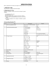
SPECIFICATION NOTE : Specifications and others are subject to change without notice for this chassis is applied to ML-051A chassis. 2. Tuning System 8. Market 6. Picture Size 7. Video input applicable system 2. Storage Environment 10. Operating Environment 9. Display Specification PAL-D/K, B/G, I, NTSC-M, SECAM NTSC 4.43 1) PAL/SECAM BG 2) PAL/SECAM DK 3) PAL I/I 4) SECAM L/L' 5) NTSC M 6) PAL-N/M 7) NTSC M VHF : E2 ~ E12 UHF : E21 ~ E69 CATV : S1 ~ S20 HYPER : S21~ S41 L/L' : B, C, D VHF : 2~13 UHF : 14~69 CATV : 1~125 VHF Low : 1 ~ M10 VHF High : 4~S22 UHF : S23~62 AC 100 ~...
SPECIFICATION NOTE : Specifications and others are subject to change without notice for this chassis is applied to ML-051A chassis. 2. Tuning System 8. Market 6. Picture Size 7. Video input applicable system 2. Storage Environment 10. Operating Environment 9. Display Specification PAL-D/K, B/G, I, NTSC-M, SECAM NTSC 4.43 1) PAL/SECAM BG 2) PAL/SECAM DK 3) PAL I/I 4) SECAM L/L' 5) NTSC M 6) PAL-N/M 7) NTSC M VHF : E2 ~ E12 UHF : E21 ~ E69 CATV : S1 ~ S20 HYPER : S21~ S41 L/L' : B, C, D VHF : 2~13 UHF : 14~69 CATV : 1~125 VHF Low : 1 ~ M10 VHF High : 4~S22 UHF : S23~62 AC 100 ~...
Service Manual
Page 7
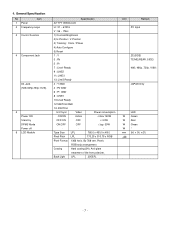
4. Pixels RGB strip arrangement Coating Hard coating(3H), Anti-glare treatment of the front polarizer, Back Light LPL 20EEFL Unit Remark PC Input ZE(SIDE) TE/ME(REAR, SIDE) 480i, 480p, 720p, 1080i JAPAN Only LED W Green W Red W Green W* mm (H) x (V) x (D) -7- By 768 vert. Type Size LPL 760.0 x 450.0 x 48.0 Pixel Pitch LPL 170.25 x 510.75 x RGB Pixel Format 1366 horiz. General Specification No Item 1 Panel 2 Frequency range 3 Control Function 4 Component Jack D4 Jack (525i,525p,750p,1125i) 5 Power ON Stand by DPMS Mode Power off 6 LCD Module Specification 32" ...
4. Pixels RGB strip arrangement Coating Hard coating(3H), Anti-glare treatment of the front polarizer, Back Light LPL 20EEFL Unit Remark PC Input ZE(SIDE) TE/ME(REAR, SIDE) 480i, 480p, 720p, 1080i JAPAN Only LED W Green W Red W Green W* mm (H) x (V) x (D) -7- By 768 vert. Type Size LPL 760.0 x 450.0 x 48.0 Pixel Pitch LPL 170.25 x 510.75 x RGB Pixel Format 1366 horiz. General Specification No Item 1 Panel 2 Frequency range 3 Control Function 4 Component Jack D4 Jack (525i,525p,750p,1125i) 5 Power ON Stand by DPMS Mode Power off 6 LCD Module Specification 32" ...
Service Manual
Page 9
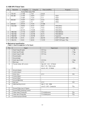
HDMI INPUT Mode Table No Resolution 1 720x400 2 640x480 3 800x600 4 832x624 5 1024x768 6 1280x768 7 1360x768 8 1366x768 9 1920x1080 10 1280x720 H-freq(kHz) V-freq.(Hz) Analog RGB, Digital RGB 31.468 70.8 31.469 59.94 37.684 75.00 37.879 60.31 46.875 75 49.725 74.55 48.363 60.00 56.47 70.00 60.123 75.029 47.776 59.870 47.720 59.799 47.720 59.799 33.75 60.00 45.00 60.00 9. AV Mode Mid (5 - 8V) - Wide Screen Low (0 - 2V) - TV Mode - 0.7 V 0.7 V High (1 - 3V) - Composite 1V including sync 1V including sync - Mechanical specification Scart Arrangement ...
HDMI INPUT Mode Table No Resolution 1 720x400 2 640x480 3 800x600 4 832x624 5 1024x768 6 1280x768 7 1360x768 8 1366x768 9 1920x1080 10 1280x720 H-freq(kHz) V-freq.(Hz) Analog RGB, Digital RGB 31.468 70.8 31.469 59.94 37.684 75.00 37.879 60.31 46.875 75 49.725 74.55 48.363 60.00 56.47 70.00 60.123 75.029 47.776 59.870 47.720 59.799 47.720 59.799 33.75 60.00 45.00 60.00 9. AV Mode Mid (5 - 8V) - Wide Screen Low (0 - 2V) - TV Mode - 0.7 V 0.7 V High (1 - 3V) - Composite 1V including sync 1V including sync - Mechanical specification Scart Arrangement ...
Service Manual
Page 10
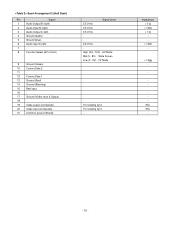
AV Mode Mid (5 - 8V) - Impedance < 1 > 10 < 1 > 10 - > 10 - - - 75 75 - - 10 - TV Mode - - - 1V including sync 1V including sync - Wide Screen Low (0 - 2V) - Scart Arrangement 2.(Half Scart) Pin Signal 1 Audio Output B (right) 2 Audio Input B (right) 3 Audio Output A (left) 4 Ground (audio) 5 Ground (blue) 6 Audio input A (left) 7 - 8 Function Select (AV control) 9 Ground (Green) 10 Comms Data 2 11 - 12 Comms Data 1 13 Ground (Red) 14 Ground (Blanking) 15 Red input 16 - 17 Ground (Video input & Output) 18 - 19 Video output (Composite) 20 ...
AV Mode Mid (5 - 8V) - Impedance < 1 > 10 < 1 > 10 - > 10 - - - 75 75 - - 10 - TV Mode - - - 1V including sync 1V including sync - Wide Screen Low (0 - 2V) - Scart Arrangement 2.(Half Scart) Pin Signal 1 Audio Output B (right) 2 Audio Input B (right) 3 Audio Output A (left) 4 Ground (audio) 5 Ground (blue) 6 Audio input A (left) 7 - 8 Function Select (AV control) 9 Ground (Green) 10 Comms Data 2 11 - 12 Comms Data 1 13 Ground (Red) 14 Ground (Blanking) 15 Red input 16 - 17 Ground (Video input & Output) 18 - 19 Video output (Composite) 20 ...
Service Manual
Page 11
...00 00 00 00 00 00 00 00 00 00 00 1E 3.2.4 Detail EDID Options are below(a, b, c, d, e) a. Product ID Model name 26LX2R 32LX2R 32LP1R 37LP1R 42LP1R Product ID 22039(A) 22040(A) 30041(A) 30042(D) 30039(A) 30040(D) 30043(A) 30044(D) 40013(A) 40014(D) Product ID Dec Hex EDID Table 22039(A) 5617...220V, 50/60Hz. 2.5 Before adjustment, execute Heat-Run for 30 minutes at RF no signal. 3. Never connect HDMI & DVI-D & DVI-A Cable at LG TV Plant 2. EDID * Caution - Use the proper cables below for EDID Download Analog EDID: Pin3 exists Digital EDID: Pin3 exists Caution: - Serial No ...
...00 00 00 00 00 00 00 00 00 00 00 1E 3.2.4 Detail EDID Options are below(a, b, c, d, e) a. Product ID Model name 26LX2R 32LX2R 32LP1R 37LP1R 42LP1R Product ID 22039(A) 22040(A) 30041(A) 30042(D) 30039(A) 30040(D) 30043(A) 30044(D) 40013(A) 40014(D) Product ID Dec Hex EDID Table 22039(A) 5617...220V, 50/60Hz. 2.5 Before adjustment, execute Heat-Run for 30 minutes at RF no signal. 3. Never connect HDMI & DVI-D & DVI-A Cable at LG TV Plant 2. EDID * Caution - Use the proper cables below for EDID Download Analog EDID: Pin3 exists Digital EDID: Pin3 exists Caution: - Serial No ...
Service Manual
Page 12
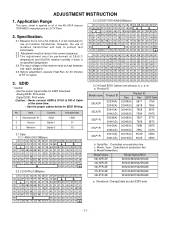
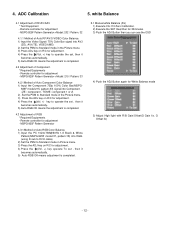
MSPG-925F Pattern Generator->Model: 215 / Pattern: 33 4.2.1 Method of Auto Component Color Balance 1) Input the Component 720p 100% Color Bar(MSPG- 925F model:215, pattern:33) signal into Component. (ZE : component , TE/ME : component 1 or 2) 2) Set the PSM to Standard mode in the Picture menu. 3) Press the ADJ key on R/C for adjustment - Remote controller for adjustment. 4) Press the (Vol. +) key to Standard mode in Picture menu. 3) Press the ADJ key on R/C for adjustment - MSPG-925F Pattern Generator 4.3.1 Method of Auto RGB Color Balance 1) Input the PC 1024x768@60Hz 1/2 Black &...
MSPG-925F Pattern Generator->Model: 215 / Pattern: 33 4.2.1 Method of Auto Component Color Balance 1) Input the Component 720p 100% Color Bar(MSPG- 925F model:215, pattern:33) signal into Component. (ZE : component , TE/ME : component 1 or 2) 2) Set the PSM to Standard mode in the Picture menu. 3) Press the ADJ key on R/C for adjustment - Remote controller for adjustment. 4) Press the (Vol. +) key to Standard mode in Picture menu. 3) Press the ADJ key on R/C for adjustment - MSPG-925F Pattern Generator 4.3.1 Method of Auto RGB Color Balance 1) Input the PC 1024x768@60Hz 1/2 Black &...
Service Manual
Page 13
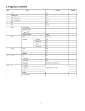
Shipping Conditions No 1 Power 2 Volume Level 3 Main Picture Input 4 Main Last Channel 5 Mute 6 ARC 7 Station 8 Picture Item Auto Program Manual Program Program Edit Favorite Program PSM Dynamic 9 Sound 10 Special 11 PC SSM AVL Balance Input Child Lock Auto sleep Language H-Position V-Position Clock Phase Auto Configue Contrast Brightness Colour Sharpness Off 30 TV Pr 01 Off 16 : 9 Condition None Dynamic 100 45 50 50 Flat Off 0 TV Off Off English(Area Management) Variable by each mode Remark - 13 - 6.
Shipping Conditions No 1 Power 2 Volume Level 3 Main Picture Input 4 Main Last Channel 5 Mute 6 ARC 7 Station 8 Picture Item Auto Program Manual Program Program Edit Favorite Program PSM Dynamic 9 Sound 10 Special 11 PC SSM AVL Balance Input Child Lock Auto sleep Language H-Position V-Position Clock Phase Auto Configue Contrast Brightness Colour Sharpness Off 30 TV Pr 01 Off 16 : 9 Condition None Dynamic 100 45 50 50 Flat Off 0 TV Off Off English(Area Management) Variable by each mode Remark - 13 - 6.
Service Manual
Page 14
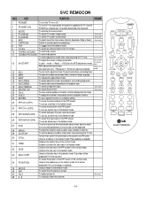
To use as a red key in the teletext mode 24 PIP CH+(OP2) To move the channel in the PIP screen To use as a green key in the teletext mode To switch between the main and sub screens 25 PIP SWAP(OP3) To use as a yellow key in the teletext mode To select the input status in the PIP screen 26 PIP INPUT(OP4) To use as a blue key in the teletext mode 27 EYE To set a function that will automatically adjust screen status to deactivate): It should be deactivated when delivered. 3 MUTE 4 P-CHECK To activate the mute function. Shortcut keys - 14 - To check TV screen image easily. To adjust ...
To use as a red key in the teletext mode 24 PIP CH+(OP2) To move the channel in the PIP screen To use as a green key in the teletext mode To switch between the main and sub screens 25 PIP SWAP(OP3) To use as a yellow key in the teletext mode To select the input status in the PIP screen 26 PIP INPUT(OP4) To use as a blue key in the teletext mode 27 EYE To set a function that will automatically adjust screen status to deactivate): It should be deactivated when delivered. 3 MUTE 4 P-CHECK To activate the mute function. Shortcut keys - 14 - To check TV screen image easily. To adjust ...
Service Manual
Page 15
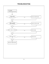
TROUBLESHOOTING NO POWER (POWER INDICATOR OFF) CHECK CN804 VOLTAGE (P-ST_5V) Yes CHECK CRYCTAL X800(19.6608MHZ) Yes CHECK IC806 VOLTAGE (5V) Yes CHECK Power on/off (5V) Yes REPLACE POWER BOARD CHECK POWER BOARD No CHECK CRYSTAL X800 No CHECK IC806 No CHECK Q1001 No - 15 -
TROUBLESHOOTING NO POWER (POWER INDICATOR OFF) CHECK CN804 VOLTAGE (P-ST_5V) Yes CHECK CRYCTAL X800(19.6608MHZ) Yes CHECK IC806 VOLTAGE (5V) Yes CHECK Power on/off (5V) Yes REPLACE POWER BOARD CHECK POWER BOARD No CHECK CRYSTAL X800 No CHECK IC806 No CHECK Q1001 No - 15 -
Service Manual
Page 16
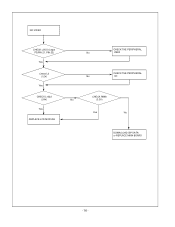
NO VIDEO CHECK LVDS Output P3(PIN 21, PIN 22) Yes Check L2 (12V) Yes CHECK L1022 (24V) Yes REPLACE LCD MODULE CHECK THE PERIPHERAL No IC800 CHECK THE PERIPHERAL No IC1 CHECK R898 No (3.3V) Yes No DOWN LOAD ISP DATA or REPLACE MAIN BOARD - 16 -
NO VIDEO CHECK LVDS Output P3(PIN 21, PIN 22) Yes Check L2 (12V) Yes CHECK L1022 (24V) Yes REPLACE LCD MODULE CHECK THE PERIPHERAL No IC800 CHECK THE PERIPHERAL No IC1 CHECK R898 No (3.3V) Yes No DOWN LOAD ISP DATA or REPLACE MAIN BOARD - 16 -
Service Manual
Page 17
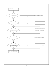
Yes DOES IC300 OPERATE? Yes REPLACE JACK BOARD INSERT CABLES WELL No CHECK IC302 OR CHANGE No CHECK IC301 OR CHANGE No CHECK X300 OR CHANGE No CHECK X400 OR CHANGE No - 17 - Yes DOES IC302 OPERATE? Yes DOES IC301 OPERATE? NO SOUND IS THE SPK CABLE CONNECTED WELL? Yes DOES IC400 OPERATE?
Yes DOES IC300 OPERATE? Yes REPLACE JACK BOARD INSERT CABLES WELL No CHECK IC302 OR CHANGE No CHECK IC301 OR CHANGE No CHECK X300 OR CHANGE No CHECK X400 OR CHANGE No - 17 - Yes DOES IC302 OPERATE? Yes DOES IC301 OPERATE? NO SOUND IS THE SPK CABLE CONNECTED WELL? Yes DOES IC400 OPERATE?
Service Manual
Page 21
... 6304FLP332A LCD(LIQUID CRYSTAL DISPLAY), LC320W01-SL05 LG PHILPS TFT COLOR (SL01, D-IC,INV. MULTI) 030 3809TKE030T BACK COVER ASSEMBLY, 32LX2R-TE TORNADO 3808TKE025 SET 3809TKE030U BACK COVER ASSEMBLY, 32LX2R-TE TORNADO 3808TKE025 CSKD 040 3043TKK252B TILT SWIVEL ASSEMBLY, 32LX2R-ZE STAND ASSY 3043TKK252E TILT SWIVEL ASSEMBLY, 32LX2R-ZE CSKD STAND ASSY 3043TKK252J TILT SWIVEL...
... 6304FLP332A LCD(LIQUID CRYSTAL DISPLAY), LC320W01-SL05 LG PHILPS TFT COLOR (SL01, D-IC,INV. MULTI) 030 3809TKE030T BACK COVER ASSEMBLY, 32LX2R-TE TORNADO 3808TKE025 SET 3809TKE030U BACK COVER ASSEMBLY, 32LX2R-TE TORNADO 3808TKE025 CSKD 040 3043TKK252B TILT SWIVEL ASSEMBLY, 32LX2R-ZE STAND ASSY 3043TKK252E TILT SWIVEL ASSEMBLY, 32LX2R-ZE CSKD STAND ASSY 3043TKK252J TILT SWIVEL...

Service Manual
Page 22
DATE: 2005. 09. 06. PART NO. DESCRIPTION / SPECIFICATION C1008 C1010 C1011 C1014 C1015 C1016 C1017 C1020 C1021 C1022 C1024 C1026 C1031 C1032 C1033 C1034 C1041 C1043 C1046 C1047 C1050 C1051 C1052 C1053 C1056 C1057 C1058 C1059 C1062 C1063 C1065 C1066 C1067 C1068 C1071 C1072 C1074 C1076 C1079 C1080 C1086 C1087 C1088 C1089 C1092 C1093 C1094 C1095 C1098 C1099 C1102 C1103 C1104 C1108 C1109 C1111 C1113 C1116 C1118 C1119 C1120 C1121 C1122 C1123 0CH3104K566 0CH3104K566 0CH3103K516 0CH3103K516 0CH3104K566 0CH3104K566 0CH3103K516 0CH3103K516 0CH3104K566 0CH3104K566 0CH3104K566 0CH3103K516 ...
DATE: 2005. 09. 06. PART NO. DESCRIPTION / SPECIFICATION C1008 C1010 C1011 C1014 C1015 C1016 C1017 C1020 C1021 C1022 C1024 C1026 C1031 C1032 C1033 C1034 C1041 C1043 C1046 C1047 C1050 C1051 C1052 C1053 C1056 C1057 C1058 C1059 C1062 C1063 C1065 C1066 C1067 C1068 C1071 C1072 C1074 C1076 C1079 C1080 C1086 C1087 C1088 C1089 C1092 C1093 C1094 C1095 C1098 C1099 C1102 C1103 C1104 C1108 C1109 C1111 C1113 C1116 C1118 C1119 C1120 C1121 C1122 C1123 0CH3104K566 0CH3104K566 0CH3103K516 0CH3103K516 0CH3104K566 0CH3104K566 0CH3103K516 0CH3103K516 0CH3104K566 0CH3104K566 0CH3104K566 0CH3103K516 ...
Service Manual
Page 28
...SW1206 140-313B SW1207 140-313B TACT 2LEAD 160G(TA) LG C&D TACT 2LEAD 160G(TA) LG C&D TACT 2LEAD 160G(TA) LG C&D TACT 2LEAD 160G(TA) LG C&D TACT 2LEAD 160G(TA) LG C&D TACT 2LEAD 160G(TA) LG C&D TACT 2LEAD 160G(TA) LG C&D *S *AL LOC. DESCRIPTION / SPECIFICATION SW1208 140-...313B R2111 0RH3001D622 R2112 0RH3001D622 R2113 0RH1502D622 R2114 0RH1000D622 R2115 0RH1301D622 R2116 0RH5601D622 R2117 0RH1301D622 R2118 0RH1000D622 R2119 0RH5601D622 R2120 0RH1502D622 TACT 2LEAD 160G(TA) LG C&D 3K OHM 1 / 10 W 2012 5.00% 3K OHM 1 / 10 W 2012 5.00% 15K OHM 1 / 10 W 2012 5.00% 100 OHM 1 / 10 W 2012 5.00...
...SW1206 140-313B SW1207 140-313B TACT 2LEAD 160G(TA) LG C&D TACT 2LEAD 160G(TA) LG C&D TACT 2LEAD 160G(TA) LG C&D TACT 2LEAD 160G(TA) LG C&D TACT 2LEAD 160G(TA) LG C&D TACT 2LEAD 160G(TA) LG C&D TACT 2LEAD 160G(TA) LG C&D *S *AL LOC. DESCRIPTION / SPECIFICATION SW1208 140-...313B R2111 0RH3001D622 R2112 0RH3001D622 R2113 0RH1502D622 R2114 0RH1000D622 R2115 0RH1301D622 R2116 0RH5601D622 R2117 0RH1301D622 R2118 0RH1000D622 R2119 0RH5601D622 R2120 0RH1502D622 TACT 2LEAD 160G(TA) LG C&D 3K OHM 1 / 10 W 2012 5.00% 3K OHM 1 / 10 W 2012 5.00% 15K OHM 1 / 10 W 2012 5.00% 100 OHM 1 / 10 W 2012 5.00...
Service Manual
Page 29
NO. PART NO. DESCRIPTION / SPECIFICATION LED804 0DLBE0158AA LED805 0DLBE0158AA LED806 0DLBE0158AA LED807 0DLBE0158AA BRIGHT LED ELECTRONICS BL-H BRIGHT LED ELECTRONICS BL-H BRIGHT LED ELECTRONICS BL-H BRIGHT LED ELECTRONICS BL-H SIDE BOARD C3103 0CH6102K406 C3104 0CH6102K406 L3108 6210TCE001A L3109 6210TCE001A R3100 0RH0000D622 R3101 0RH4703D622 R3102 0RH4703D622 R3103 0RH0000D622 R3104 0RH0000D622 R3111 0RH0752D622 R3113 0RH0752D622 R3115 0RH0752D622 R3117 0RH4703D622 R3119 0RH4703D622 R3123 0RH0000D622 R3124 0RH0000D622 R3160 0RH1001D622 ZD3105 0DZ510009EE ZD3106 0DZ510009EE ZD3107 ...
NO. PART NO. DESCRIPTION / SPECIFICATION LED804 0DLBE0158AA LED805 0DLBE0158AA LED806 0DLBE0158AA LED807 0DLBE0158AA BRIGHT LED ELECTRONICS BL-H BRIGHT LED ELECTRONICS BL-H BRIGHT LED ELECTRONICS BL-H BRIGHT LED ELECTRONICS BL-H SIDE BOARD C3103 0CH6102K406 C3104 0CH6102K406 L3108 6210TCE001A L3109 6210TCE001A R3100 0RH0000D622 R3101 0RH4703D622 R3102 0RH4703D622 R3103 0RH0000D622 R3104 0RH0000D622 R3111 0RH0752D622 R3113 0RH0752D622 R3115 0RH0752D622 R3117 0RH4703D622 R3119 0RH4703D622 R3123 0RH0000D622 R3124 0RH0000D622 R3160 0RH1001D622 ZD3105 0DZ510009EE ZD3106 0DZ510009EE ZD3107 ...
