Owners Manual
Page 6
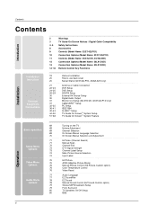
... Controls (Model Name: 32/37/42LP1D) Connection Options (Model Name: 32/37/42LP1D) Controls (Model Name: 26/32LX1D, 26/32LX2D) Connection Options (Model Name: 26LX1D/2D) Connection Options (Model Name: 32LX1D/2D) Remote Control Key Functions 19 20 20 21 22~23 24~25 26~29 30 30 31 31 32~35...37/42LP1D, 26/32LX2D only) Antenna or Cable Connection VCR Setup DVD Setup HDSTB Setup External AV Source Setup Digital Audio Output Monitor Out Setup (32LX1D/2D, 32/37/42LP1D only) CableCARDTM Setup PC Setup IEEE1394 G-LINKTM Setup TV Guide On ScreenTM System Setup TV Guide On ScreenTM System Feature ...
... Controls (Model Name: 32/37/42LP1D) Connection Options (Model Name: 32/37/42LP1D) Controls (Model Name: 26/32LX1D, 26/32LX2D) Connection Options (Model Name: 26LX1D/2D) Connection Options (Model Name: 32LX1D/2D) Remote Control Key Functions 19 20 20 21 22~23 24~25 26~29 30 30 31 31 32~35...37/42LP1D, 26/32LX2D only) Antenna or Cable Connection VCR Setup DVD Setup HDSTB Setup External AV Source Setup Digital Audio Output Monitor Out Setup (32LX1D/2D, 32/37/42LP1D only) CableCARDTM Setup PC Setup IEEE1394 G-LINKTM Setup TV Guide On ScreenTM System Setup TV Guide On ScreenTM System Feature ...

Owners Manual
Page 7
... OSD Display 101 MP3 File Selection and Popup menu 101 Screen Saver 102~107 External Control Device Setup 108~109 IR Codes 110 Programming the Remote 111~112 Programming Codes 113~114 Troubleshooting Checklist 115 Maintenance 115 Product Specifications 7 Reference
... OSD Display 101 MP3 File Selection and Popup menu 101 Screen Saver 102~107 External Control Device Setup 108~109 IR Codes 110 Programming the Remote 111~112 Programming Codes 113~114 Troubleshooting Checklist 115 Maintenance 115 Product Specifications 7 Reference

Owners Manual
Page 8
PIP ADJUST CH+ PIP EZ SWAP SOUND EJECT FLASHBK INPUT 9 6 1.5V 1.5V Remote Control / Batteries 8 Twister Holder Arrange the wires with your TV. Owner's Manual D-sub 15 pin cable DAY MENU TV INPUT TV AUDIO POWER CABMLEODDEVD TV/...
PIP ADJUST CH+ PIP EZ SWAP SOUND EJECT FLASHBK INPUT 9 6 1.5V 1.5V Remote Control / Batteries 8 Twister Holder Arrange the wires with your TV. Owner's Manual D-sub 15 pin cable DAY MENU TV INPUT TV AUDIO POWER CABMLEODDEVD TV/...

Owners Manual
Page 9
... is a simplified representation of front panel. - When the TV is switched on, blinks green and then illuminates green. Introduction Controls (Model Name: 32/37/42LP1D) - Remote Control Sensor DTV, CADTV mode TV, CATV, DTV, CADTV mode Video1-2 mode Component1-2 mode PC mode HDMI mode 1394 IEEE IEEE1394 Stereo mode mode CH...
... is a simplified representation of front panel. - When the TV is switched on, blinks green and then illuminates green. Introduction Controls (Model Name: 32/37/42LP1D) - Remote Control Sensor DTV, CADTV mode TV, CATV, DTV, CADTV mode Video1-2 mode Component1-2 mode PC mode HDMI mode 1394 IEEE IEEE1394 Stereo mode mode CH...

Owners Manual
Page 10
... INPUT / COMPONENT1 INPUT MONITOR OUT HDMI / IEEE1394 Port AUDIO/VIDEO INPUT1 CableCARDTM Slot AC IN HDMI G-LINK DIGITAL AUDIO (OPTICAL) OUTPUT REMOTE RS-232C INPUT CONTROL (CONTROL/SERVICE) DVI INPUT R AUDIO L (MONO) VIDEO S-VIDEO MONITOR OUT VIDEO1 CABLE IEEE 1394 COMPONENT1 PC ...INPUT VIDEO INPUT ANTENNA CableCARD RS-232C INPUT (CONTROL/SERVICE) / RGB INPUT (PC/DTV INPUT) ANTENNA Input PC AUDIO INPUT CABLE Input REMOTE CONTROL Port COMPONENT1 (VIDEO / AUDIO INPUT) * The HDMI port can receive video via High-Definition Multimedia Interface (HDMI) or the Digital Visual...
... INPUT / COMPONENT1 INPUT MONITOR OUT HDMI / IEEE1394 Port AUDIO/VIDEO INPUT1 CableCARDTM Slot AC IN HDMI G-LINK DIGITAL AUDIO (OPTICAL) OUTPUT REMOTE RS-232C INPUT CONTROL (CONTROL/SERVICE) DVI INPUT R AUDIO L (MONO) VIDEO S-VIDEO MONITOR OUT VIDEO1 CABLE IEEE 1394 COMPONENT1 PC ...INPUT VIDEO INPUT ANTENNA CableCARD RS-232C INPUT (CONTROL/SERVICE) / RGB INPUT (PC/DTV INPUT) ANTENNA Input PC AUDIO INPUT CABLE Input REMOTE CONTROL Port COMPONENT1 (VIDEO / AUDIO INPUT) * The HDMI port can receive video via High-Definition Multimedia Interface (HDMI) or the Digital Visual...

Owners Manual
Page 11
Introduction Controls (Model Name: 26/32LX1D, 26/32LX2D) - When the TV is in standby mode. CH VOL MENU TV/ VIDEO/ TV GUIDE ON/OFF ON/OFF Button TV GUIDE Button TV/VIDEO / Button MENU Button VOLUME (F,G) Buttons CHANNEL (E, D) Buttons 11 Remote Control Sensor /Power Standby Indicator Illuminates red when the TV is switched on, blinks green and then illuminates green. This is a simplified representation of front panel. - Here shown may be somewhat different from your TV.
Introduction Controls (Model Name: 26/32LX1D, 26/32LX2D) - When the TV is in standby mode. CH VOL MENU TV/ VIDEO/ TV GUIDE ON/OFF ON/OFF Button TV GUIDE Button TV/VIDEO / Button MENU Button VOLUME (F,G) Buttons CHANNEL (E, D) Buttons 11 Remote Control Sensor /Power Standby Indicator Illuminates red when the TV is switched on, blinks green and then illuminates green. This is a simplified representation of front panel. - Here shown may be somewhat different from your TV.

Owners Manual
Page 12
.../ DVI INPUT / COMPONENT1 INPUT G-LINKTM Port AUDIO/VIDEO INPUT1 HDMI / IEEE1394 Port CableCARDTM Slot AC IN G-LINK DIGITAL AUDIO OUTPUT (OPTICAL) REMOTE RS-232C INPUT DVI INPUT CONTROL (CONTROL/SERVICE PORT) PC AUDIO RGB INPUT COMPONENT1 INPUT INPUT (PC/DTV INPUT) R AUDIO L (MONO) ...L CableCARD CABLE ANTENNA AUDIO INPUT RS-232C INPUT (CONTROL/SERVICE) / RGB INPUT (PC/DTV INPUT) ANTENNA Input CABLE Input PC AUDIO INPUT REMOTE CONTROL Port COMPONENT1 (VIDEO / AUDIO INPUT) * The HDMI port can receive video via High-Definition Multimedia Interface (HDMI) or the Digital Visual...
.../ DVI INPUT / COMPONENT1 INPUT G-LINKTM Port AUDIO/VIDEO INPUT1 HDMI / IEEE1394 Port CableCARDTM Slot AC IN G-LINK DIGITAL AUDIO OUTPUT (OPTICAL) REMOTE RS-232C INPUT DVI INPUT CONTROL (CONTROL/SERVICE PORT) PC AUDIO RGB INPUT COMPONENT1 INPUT INPUT (PC/DTV INPUT) R AUDIO L (MONO) ...L CableCARD CABLE ANTENNA AUDIO INPUT RS-232C INPUT (CONTROL/SERVICE) / RGB INPUT (PC/DTV INPUT) ANTENNA Input CABLE Input PC AUDIO INPUT REMOTE CONTROL Port COMPONENT1 (VIDEO / AUDIO INPUT) * The HDMI port can receive video via High-Definition Multimedia Interface (HDMI) or the Digital Visual...

Owners Manual
Page 13
... INPUT / COMPONENT1 INPUT MONITOR OUT HDMI / IEEE1394 Port AUDIO/VIDEO INPUT1 CableCARDTM Slot AC IN HDMI G-LINK DIGITAL AUDIO (OPTICAL) OUTPUT REMOTE RS-232C INPUT CONTROL (CONTROL/SERVICE) DVI INPUT R AUDIO L (MONO) VIDEO S-VIDEO MONITOR OUT VIDEO1 CABLE IEEE 1394 COMPONENT1 PC ... INPUT VIDEO INPUT ANTENNA CableCARD RS-232C INPUT (CONTROL/SERVICE) / RGB INPUT (PC/DTV INPUT) PC AUDIO INPUT ANTENNA Input CABLE Input REMOTE CONTROL Port COMPONENT1 (VIDEO / AUDIO INPUT) * The HDMI port can receive video via High-Definition Multimedia Interface (HDMI) or the Digital ...
... INPUT / COMPONENT1 INPUT MONITOR OUT HDMI / IEEE1394 Port AUDIO/VIDEO INPUT1 CableCARDTM Slot AC IN HDMI G-LINK DIGITAL AUDIO (OPTICAL) OUTPUT REMOTE RS-232C INPUT CONTROL (CONTROL/SERVICE) DVI INPUT R AUDIO L (MONO) VIDEO S-VIDEO MONITOR OUT VIDEO1 CABLE IEEE 1394 COMPONENT1 PC ... INPUT VIDEO INPUT ANTENNA CableCARD RS-232C INPUT (CONTROL/SERVICE) / RGB INPUT (PC/DTV INPUT) PC AUDIO INPUT ANTENNA Input CABLE Input REMOTE CONTROL Port COMPONENT1 (VIDEO / AUDIO INPUT) * The HDMI port can receive video via High-Definition Multimedia Interface (HDMI) or the Digital ...

Owners Manual
Page 14
..., Video1-2, Component 1-2, RGB-DTV (or RGB-PC), HDMI/DVI). (Video 1-2, Component 1-2 input sources are linked automatically, Only if these are connected) MODE Selects the remote operating mode: TV, VCR, DVD, CABLE, STB or AUDIO. INFO (Refer to p.93) When you to navigate the on top of the screen. PIP CH...+ PIP INPUT TIMER RATIO ADJUST SWAP SAP EZ PIC APM EZ SOUND CC FREEZE AUTO DEMO M/C EJECT LIGHT Illuminates the remote control buttons. Not available in the TV Guide On Screen system. Enters or exits a Panel Menu in Component 1-2, RGB and HDMI/DVI mode. TV...
..., Video1-2, Component 1-2, RGB-DTV (or RGB-PC), HDMI/DVI). (Video 1-2, Component 1-2 input sources are linked automatically, Only if these are connected) MODE Selects the remote operating mode: TV, VCR, DVD, CABLE, STB or AUDIO. INFO (Refer to p.93) When you to navigate the on top of the screen. PIP CH...+ PIP INPUT TIMER RATIO ADJUST SWAP SAP EZ PIC APM EZ SOUND CC FREEZE AUTO DEMO M/C EJECT LIGHT Illuminates the remote control buttons. Not available in the TV Guide On Screen system. Enters or exits a Panel Menu in Component 1-2, RGB and HDMI/DVI mode. TV...

Owners Manual
Page 16
... new ones. 3 Close the cover. 16 TV INPUT POWER TV AUDIO DVD MODE CABLE TV/VIDEO VCR STB DAY MENU DAY+ TV GUIDE ENTER * Use a remote control 7 meter distance and 30 degree (left/right) within the receiving unit scope. * Dispose of used batteries in PIP/Twin picture mode. FREEZE Freezes the...
... new ones. 3 Close the cover. 16 TV INPUT POWER TV AUDIO DVD MODE CABLE TV/VIDEO VCR STB DAY MENU DAY+ TV GUIDE ENTER * Use a remote control 7 meter distance and 30 degree (left/right) within the receiving unit scope. * Dispose of used batteries in PIP/Twin picture mode. FREEZE Freezes the...

Owners Manual
Page 20
...PC INPUT) L AUDIO R AV1 AV2 MONITOR OUT Antenna LOOP THROUGH Swivel Stand (32/37/42LP1D, 26/32LX2D only) - HDMI UPGRADE PORT PC SOUND REMOTE CONTROL VIDEO DVI INPUT (PC INPUT) L AUDIO R AV1 AV2 MONITOR OUT Antenna LOOPTHROUGH 4 Reinstall the cover. Wire Arrangement - Pull the cables through the... hole on its stand 30° to the left or right to provide the optimum viewing angle. 20 HDMI UPGRADE PORT PC SOUND REMOTE CONTROL VIDEO DVI INPUT (PC INPUT) L AUDIO R AV1 AV2 MONITOR OUT Antenna LOOP THROUGH 2 Install wires as necessary. (To install various...
...PC INPUT) L AUDIO R AV1 AV2 MONITOR OUT Antenna LOOP THROUGH Swivel Stand (32/37/42LP1D, 26/32LX2D only) - HDMI UPGRADE PORT PC SOUND REMOTE CONTROL VIDEO DVI INPUT (PC INPUT) L AUDIO R AV1 AV2 MONITOR OUT Antenna LOOPTHROUGH 4 Reinstall the cover. Wire Arrangement - Pull the cables through the... hole on its stand 30° to the left or right to provide the optimum viewing angle. 20 HDMI UPGRADE PORT PC SOUND REMOTE CONTROL VIDEO DVI INPUT (PC INPUT) L AUDIO R AV1 AV2 MONITOR OUT Antenna LOOP THROUGH 2 Install wires as necessary. (To install various...
Owners Manual
Page 22
If connected to the VCR owner's manual.) 3 Select Video1 input source using the TV/VIDEO button on the remote control. - If the 4:3 picture format is used; Typically a frozen still picture from the VCR to the AUDIO L/MONO jack of the set . 2 Connect the antenna ...
If connected to the VCR owner's manual.) 3 Select Video1 input source using the TV/VIDEO button on the remote control. - If the 4:3 picture format is used; Typically a frozen still picture from the VCR to the AUDIO L/MONO jack of the set . 2 Connect the antenna ...

Owners Manual
Page 23
... VIDEO2), select Video2 input source. compared to normal composite (RCA cable) input. 2 Connect the audio outputs of the VCR to the S-VIDEO input on the remote control. - If connected to both Video and S-Video at the same time. 23 The picture quality is improved; Installation When connecting with using the TV...
... VIDEO2), select Video2 input source. compared to normal composite (RCA cable) input. 2 Connect the audio outputs of the VCR to the S-VIDEO input on the remote control. - If connected to both Video and S-Video at the same time. 23 The picture quality is improved; Installation When connecting with using the TV...

Owners Manual
Page 24
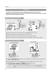
... DVD player's manual for operating instructions. 24 • TV can receive the video and audio signal simultaneously with using the TV/VIDEO button on the remote control. - When connecting with a HDMI cable 32, 37, 42 inch TV Back HDMI IEEE 1394 CableCARD 1 CABLE ANTENNA HDMI-DVD OUPUT DVD 26 ...8226; If the DVD does not support Auto HDMI, you need to set . 2 Select HDMI input source with using the TV/VIDEO button on the remote control. 3 Refer to the DVD player's manual for operating instructions. If connected to IN2 (or VIDEO2), select Video 2 input source. 5 Refer to 1280x720p...
... DVD player's manual for operating instructions. 24 • TV can receive the video and audio signal simultaneously with using the TV/VIDEO button on the remote control. - When connecting with a HDMI cable 32, 37, 42 inch TV Back HDMI IEEE 1394 CableCARD 1 CABLE ANTENNA HDMI-DVD OUPUT DVD 26 ...8226; If the DVD does not support Auto HDMI, you need to set . 2 Select HDMI input source with using the TV/VIDEO button on the remote control. 3 Refer to the DVD player's manual for operating instructions. If connected to IN2 (or VIDEO2), select Video 2 input source. 5 Refer to 1280x720p...

Owners Manual
Page 25
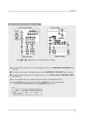
... to the COMPONENT1 VIDEO INPUT jacks on the set . 2-2 Connect the optical audio output of the DVD to the COMPONENT1 AUDIO INPUT jacks on the remote control. - Component ports on the TV Y PB PR Video output ports on your DVD connector. If connected to COMPONENT2 input, select Component 2 input source. 5 Refer...
... to the COMPONENT1 VIDEO INPUT jacks on the set . 2-2 Connect the optical audio output of the DVD to the COMPONENT1 AUDIO INPUT jacks on the remote control. - Component ports on the TV Y PB PR Video output ports on your DVD connector. If connected to COMPONENT2 input, select Component 2 input source. 5 Refer...

Owners Manual
Page 26
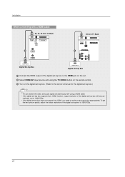
... TV Back R AUDIO L (MONO) VIDEO S-VIDEO VIDEO1 AC IN G-LINK DIGITAL AUDIO (OPTICAL) OUTPUT REMOTE RS-232C INPUT CONTROL (CONTROL/SERVICE) DVI INPUT PC AUDIO RGB INPUT COMPONENT1 INPUT (PC/DTV INPUT) ...INPUT 2 1 AC IN G-LINK DIGITAL AUDIO OUTPUT (OPTICAL) REMOTE RS-232C INPUT DVI INPUT CONTROL (CONTROL/SERVICE PORT) PC AUDIO RGB INPUT COMPONENT1 INPUT INPUT (PC/DTV...the set-top box to the PC AUDIO INPUT jack on the set. 3 Turn on the remote control. 26 However, if you do receive Digital signals from a digital set-top box or...
... TV Back R AUDIO L (MONO) VIDEO S-VIDEO VIDEO1 AC IN G-LINK DIGITAL AUDIO (OPTICAL) OUTPUT REMOTE RS-232C INPUT CONTROL (CONTROL/SERVICE) DVI INPUT PC AUDIO RGB INPUT COMPONENT1 INPUT (PC/DTV INPUT) ...INPUT 2 1 AC IN G-LINK DIGITAL AUDIO OUTPUT (OPTICAL) REMOTE RS-232C INPUT DVI INPUT CONTROL (CONTROL/SERVICE PORT) PC AUDIO RGB INPUT COMPONENT1 INPUT INPUT (PC/DTV...the set-top box to the PC AUDIO INPUT jack on the set. 3 Turn on the remote control. 26 However, if you do receive Digital signals from a digital set-top box or...
Owners Manual
Page 27
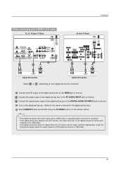
If connected to the owner's manual for the digital set-top box.) 4 Select Component 1 input source with using the TV/VIDEO button on the remote control. - Signal Component1/2 RGB-DTV, HDMI/DVI 480i Yes No 480p/720p/1080i Yes Yes 27 Installation When connecting with a Component cable 32, 37, 42 ...
If connected to the owner's manual for the digital set-top box.) 4 Select Component 1 input source with using the TV/VIDEO button on the remote control. - Signal Component1/2 RGB-DTV, HDMI/DVI 480i Yes No 480p/720p/1080i Yes Yes 27 Installation When connecting with a Component cable 32, 37, 42 ...
Owners Manual
Page 28
... the digital set-top box to the HDMI jack on the set. 2 Select HDMI/DVI input source with using the TV/VIDEO button on the remote control. 3 Turn on the digital set-top box. (Refer to the owner's manual for the digital set-top box.) • TV can receive the video...
... the digital set-top box to the HDMI jack on the set. 2 Select HDMI/DVI input source with using the TV/VIDEO button on the remote control. 3 Turn on the digital set-top box. (Refer to the owner's manual for the digital set-top box.) • TV can receive the video...
Owners Manual
Page 29
... Select HDMI/DVI input source with a HDMI to DVI cable 32, 37, 42 inch TV Back HDMI G-LINK DIGITAL AUDIO (OPTICAL) OUTPUT REMOTE RS-232C INPUT CONTROL (CONTROL/SERVICE) DVI INPUT R AUDIO L (MONO) VIDEO S-VIDEO MONITOR OUT VIDEO1 CABLE IEEE 1394 COMPONENT1 PC AUDIO ... RGB INPUT COMPONENT1 (PC/DTV INPUT) INPUT R L AUDIO INPUT VIDEO INPUT ANTENNA 1 2-1 2-2 26 inch TV Back G-LINK DIGITAL AUDIO OUTPUT (OPTICAL) REMOTE RS-232C INPUT DVI INPUT CONTROL (CONTROL/SERVICE PORT) PC AUDIO RGB INPUT COMPONENT1 INPUT INPUT (PC/DTV INPUT) 2-1 2-2 R AUDIO L (MONO) VIDEO...
... Select HDMI/DVI input source with a HDMI to DVI cable 32, 37, 42 inch TV Back HDMI G-LINK DIGITAL AUDIO (OPTICAL) OUTPUT REMOTE RS-232C INPUT CONTROL (CONTROL/SERVICE) DVI INPUT R AUDIO L (MONO) VIDEO S-VIDEO MONITOR OUT VIDEO1 CABLE IEEE 1394 COMPONENT1 PC AUDIO ... RGB INPUT COMPONENT1 (PC/DTV INPUT) INPUT R L AUDIO INPUT VIDEO INPUT ANTENNA 1 2-1 2-2 26 inch TV Back G-LINK DIGITAL AUDIO OUTPUT (OPTICAL) REMOTE RS-232C INPUT DVI INPUT CONTROL (CONTROL/SERVICE PORT) PC AUDIO RGB INPUT COMPONENT1 INPUT INPUT (PC/DTV INPUT) 2-1 2-2 R AUDIO L (MONO) VIDEO...

Owners Manual
Page 30
... the Digital Audio Output Optical port. 32, 37, 42 inch TV Back 26 inch TV Back AC IN G-LINK DIGITAL AUDIO (OPTICAL) OUTPUT REMOTE RS-232C INPUT CONTROL (CONTROL/SERVICE) DVI INPUT PC AUDIO RGB INPUT COMPONENT1 INPUT (PC/DTV INPUT) INPUT 1/2 AC IN G-LINK DIGITAL AUDIO... OUTPUT (OPTICAL) R AUDIO L (MONO) VIDEO S-VIDEO VIDEO1 REMOTE RS-232C INPUT DVI INPUT CONTROL (CONTROL/SERVICE PORT) PC AUDIO RGB INPUT COMPONENT1 INPUT INPUT (PC/DTV INPUT) 1/2 1 Connect one end of an ...
... the Digital Audio Output Optical port. 32, 37, 42 inch TV Back 26 inch TV Back AC IN G-LINK DIGITAL AUDIO (OPTICAL) OUTPUT REMOTE RS-232C INPUT CONTROL (CONTROL/SERVICE) DVI INPUT PC AUDIO RGB INPUT COMPONENT1 INPUT (PC/DTV INPUT) INPUT 1/2 AC IN G-LINK DIGITAL AUDIO... OUTPUT (OPTICAL) R AUDIO L (MONO) VIDEO S-VIDEO VIDEO1 REMOTE RS-232C INPUT DVI INPUT CONTROL (CONTROL/SERVICE PORT) PC AUDIO RGB INPUT COMPONENT1 INPUT INPUT (PC/DTV INPUT) 1/2 1 Connect one end of an ...


