
FS-C5016N Installation Guide Rev-AC
Page 1
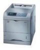
... Printer 2 Documents and Software • Installation Guide (This sheet) • Quick Reference Guide • CD-ROMs 3 Magenta Toner Container 4 Cyan Toner Container 5 Yellow Toner Container 6 Black Toner Container 7 Waste Toner Boxes (One is spare.) 8 Power Cord Make sure that are not level. FS-C5016N ...the left cover. Power Cord Connecter Continued on the center of the box into place. 14 Make sure that color. Cap To install the other color toner containers, use the printer's operation panel to perform the color registration procedure. Kyocera Mita assumes no liability...
... Printer 2 Documents and Software • Installation Guide (This sheet) • Quick Reference Guide • CD-ROMs 3 Magenta Toner Container 4 Cyan Toner Container 5 Yellow Toner Container 6 Black Toner Container 7 Waste Toner Boxes (One is spare.) 8 Power Cord Make sure that are not level. FS-C5016N ...the left cover. Power Cord Connecter Continued on the center of the box into place. 14 Make sure that color. Cap To install the other color toner containers, use the printer's operation panel to perform the color registration procedure. Kyocera Mita assumes no liability...

Service Manual
Page 19
Avoid direct light and high humidity. 1-2-2 Installation environment 1. Power supply: 120 V AC (U.S.A./Canada), 220 - 240 V AC (European countries) 4. Should it . Machine front: 600 mm/26.6" Machine rear: 250 mm/9.84" Machine right: 250 mm/9....6. Humidity: 20 - 80%RH 3. Allow sufficient access for proper operation and maintenance of the machine. Power source frequency: 50 Hz ±2%/60 Hz ±2% 5. installation location Avoid direct sunlight or bright lighting. FS-C5016N 1-2-1 Drum unit Note the following when handling or storing the drum unit. • When removing the drum...
Avoid direct light and high humidity. 1-2-2 Installation environment 1. Power supply: 120 V AC (U.S.A./Canada), 220 - 240 V AC (European countries) 4. Should it . Machine front: 600 mm/26.6" Machine rear: 250 mm/9.84" Machine right: 250 mm/9....6. Humidity: 20 - 80%RH 3. Allow sufficient access for proper operation and maintenance of the machine. Power source frequency: 50 Hz ±2%/60 Hz ±2% 5. installation location Avoid direct sunlight or bright lighting. FS-C5016N 1-2-1 Drum unit Note the following when handling or storing the drum unit. • When removing the drum...

Service Manual
Page 53
...heat roller of the fuser PWB (KP-970), if there is trouble, remedy or replace. Replace the fuser PWB (KP-970). FS-C5016N Code 6000 6020 Contents Causes Remarks Check procedures/corrective measures Fuser temperature time-out error (heat roller) • Doing the control ...poor contact of fuser thermistor 1. Defective harness (S02857: 220 - 240 V AC model, S02858: 120 V AC model) between fuser unit connector and power supply PWB. Fuser abnormal high temperature error (heat roller) • Abnormal high fuser temperature of the fuser PWB (KP970), if there is trouble, remedy...
...heat roller of the fuser PWB (KP-970), if there is trouble, remedy or replace. Replace the fuser PWB (KP-970). FS-C5016N Code 6000 6020 Contents Causes Remarks Check procedures/corrective measures Fuser temperature time-out error (heat roller) • Doing the control ...poor contact of fuser thermistor 1. Defective harness (S02857: 220 - 240 V AC model, S02858: 120 V AC model) between fuser unit connector and power supply PWB. Fuser abnormal high temperature error (heat roller) • Abnormal high fuser temperature of the fuser PWB (KP970), if there is trouble, remedy...

Service Manual
Page 54
... the connection YC694 connector of the heat roller. Defective fuser PWB (KP-970). See page 1-6-26. Defective harness (S02853) power supply PWB and fuser connector or poor contact of the connector terminals. Replace the engine controller PWB (KP1054). Defective engine controller PWB ...fuser PWB (KP-970) between fuser PWB (KP970) and fuser connector or poor contact of the connector terminals. Replace the power supply PWB. FS-C5016N Code 6030 Contents Causes Remarks Check procedures/corrective measures Fuser thermistor 1 broken error (heat roller) • It was judged...
... the connection YC694 connector of the heat roller. Defective fuser PWB (KP-970). See page 1-6-26. Defective harness (S02853) power supply PWB and fuser connector or poor contact of the connector terminals. Replace the engine controller PWB (KP1054). Defective engine controller PWB ...fuser PWB (KP-970) between fuser PWB (KP970) and fuser connector or poor contact of the connector terminals. Replace the power supply PWB. FS-C5016N Code 6030 Contents Causes Remarks Check procedures/corrective measures Fuser thermistor 1 broken error (heat roller) • It was judged...

Service Manual
Page 55
...replace. Defective harness (S02856) between fuser unit connector and fuser heater lamp 2. Replace the engine controller PWB (KP1054). Replace the power supply PWB. Check the installation condition of fuser thertion condition of the fuser PWB (KP-970), if there is trouble, remedy or ... heater lamp 2. Replace the fuser PWB (KP-970). Replace the Fuser thermostat 2. Check the installation condition of fuser thermistor 2. FS-C5016N Code 6100 6120 Contents Causes Remarks Check procedures/corrective measures Fuser temperature time-out error (press roller) • Doing the control ...
...replace. Defective harness (S02856) between fuser unit connector and fuser heater lamp 2. Replace the engine controller PWB (KP1054). Replace the power supply PWB. Check the installation condition of fuser thertion condition of the fuser PWB (KP-970), if there is trouble, remedy or ... heater lamp 2. Replace the fuser PWB (KP-970). Replace the Fuser thermostat 2. Check the installation condition of fuser thermistor 2. FS-C5016N Code 6100 6120 Contents Causes Remarks Check procedures/corrective measures Fuser temperature time-out error (press roller) • Doing the control ...

Service Manual
Page 56
...container or defectiveness of mistor 2, if there is trouble, remedy or replace. Replace the engine controller PWB (KP1054). Defective installa- Defective power supply PWB. Defective harness (S02854) between fuser thermistor 2 or poor contact of the press roller. See page 1-6-18. Replace the engine ... the POWER supply PWB is trouble, remedy or replace. Defective harness of the fuser PWB (KP-970) between fuser PWB (KP970) and fuser connector or poor contact of the fuser PWB (KP-970), if there is trouble, remedy or fuser thermistor 2. FS-C5016N Code ...
...container or defectiveness of mistor 2, if there is trouble, remedy or replace. Replace the engine controller PWB (KP1054). Defective installa- Defective power supply PWB. Defective harness (S02854) between fuser thermistor 2 or poor contact of the press roller. See page 1-6-18. Replace the engine ... the POWER supply PWB is trouble, remedy or replace. Defective harness of the fuser PWB (KP-970) between fuser PWB (KP970) and fuser connector or poor contact of the fuser PWB (KP-970), if there is trouble, remedy or fuser thermistor 2. FS-C5016N Code ...

Service Manual
Page 64
Defective sensor PWB (KP982). See page 1-6-25. Defective sensor PWB (KP982). See page 1-6-25. FS-C5016N Problem Causes Check procedures/corrective measures (6) The paper size is not cancelled. Replace the sensor PWB (KP-982). Defective engine controller Replace... PWB (KP-1054), check the connection YC701 and YC702 connectors of sensor PWB (KP-982), if there is trouble, remedy or replace. Replace the power supply PWB. Defective harness (S02849) between engine controller PWB (KP-1054) and sensor PWB (KP-982) or poor contact of the connector terminals. Defective ...
Defective sensor PWB (KP982). See page 1-6-25. Defective sensor PWB (KP982). See page 1-6-25. FS-C5016N Problem Causes Check procedures/corrective measures (6) The paper size is not cancelled. Replace the sensor PWB (KP-982). Defective engine controller Replace... PWB (KP-1054), check the connection YC701 and YC702 connectors of sensor PWB (KP-982), if there is trouble, remedy or replace. Replace the power supply PWB. Defective harness (S02849) between engine controller PWB (KP-1054) and sensor PWB (KP-982) or poor contact of the connector terminals. Defective ...

Service Manual
Page 97
.... Remove the right cover, left cover and, rear cover. (see previous page). 2. Loose the one screw. 6. (2) Detaching and refitting the engine controller PWB and power supply PWB Procedure 1. Connectors FS-C5016N Connectors Machine right Connectors 4. Remove the main controller PWB (see pages 1-6-2, 3, 4). 3. Remove three screws. 5. Remove the all (machine left Figure 1-6-33 Main frame...
.... Remove the right cover, left cover and, rear cover. (see previous page). 2. Loose the one screw. 6. (2) Detaching and refitting the engine controller PWB and power supply PWB Procedure 1. Connectors FS-C5016N Connectors Machine right Connectors 4. Remove the main controller PWB (see pages 1-6-2, 3, 4). 3. Remove three screws. 5. Remove the all (machine left Figure 1-6-33 Main frame...

Service Manual
Page 98
FS-C5016N 7. Remove the six screws and then remove the controller box cover. Remove the five screws. 9. Screws Engine controller PWB Connecotor Connecotor Connecotor 1-6-26 Figure 1-6-36 Screws Controller box cover Screws Figure 1-6-35 8. Remove the two connectors and then removing the connection with the power supply PWB, remove the engine controller PWB.
FS-C5016N 7. Remove the six screws and then remove the controller box cover. Remove the five screws. 9. Screws Engine controller PWB Connecotor Connecotor Connecotor 1-6-26 Figure 1-6-36 Screws Controller box cover Screws Figure 1-6-35 8. Remove the two connectors and then removing the connection with the power supply PWB, remove the engine controller PWB.

Service Manual
Page 99
The EEPROM (U12) removing from the socket of the old engine controller PWB, it does again to install in the socket of the new engine controller PWB. EEPROM (U12) FS-C5016N U12 11. Remove the three screws, one terminal, one washer and then remove the power supply PWB. 12. Check or replace the engine controller PWB and power supply PWB then refit all the removed parts. Engine controller PWB Figure 1-6-37 Power supply PWB Screw Terminal Washer Screws Figure 1-6-38 1-6-27 10.
The EEPROM (U12) removing from the socket of the old engine controller PWB, it does again to install in the socket of the new engine controller PWB. EEPROM (U12) FS-C5016N U12 11. Remove the three screws, one terminal, one washer and then remove the power supply PWB. 12. Check or replace the engine controller PWB and power supply PWB then refit all the removed parts. Engine controller PWB Figure 1-6-37 Power supply PWB Screw Terminal Washer Screws Figure 1-6-38 1-6-27 10.

Service Manual
Page 140
FS-C5016N To optional duplexer or face-up tray To face-down tray Change guide Upper exit roller Lower exit roller Heat roller From paper feed unit Press roller Figure 2-1-35 Fuser unit FUDR FDDR Face up/down solenoid Fuser PWB Rear cover open sensor Exit sensor Fuser thermistor 1 Power supply PWB FUSOLDR FDSOLDR EXITPAP...
FS-C5016N To optional duplexer or face-up tray To face-down tray Change guide Upper exit roller Lower exit roller Heat roller From paper feed unit Press roller Figure 2-1-35 Fuser unit FUDR FDDR Face up/down solenoid Fuser PWB Rear cover open sensor Exit sensor Fuser thermistor 1 Power supply PWB FUSOLDR FDSOLDR EXITPAP...

Service Manual
Page 141
Power supply PWB Generates 24 V DC and 5 V DC power source. LED print head relay PWB Consists the LED print head control circuit and wiring relay circuit between engine controller PWB and drum units. ... output control, paper conveying system control, and fuser temperature control, etc. 3. Engine controller PWB Controls printer hardware such as the print data processing and provides the interface with computers. 2. 2-2-1 Electrical parts layout (1) Main frame and controller box FS-C5016N ( MAIN FRAME 4 7 Ø ∏ @! ¨ ˇ › ) Í5 ˆÁ # ⁄...
Power supply PWB Generates 24 V DC and 5 V DC power source. LED print head relay PWB Consists the LED print head control circuit and wiring relay circuit between engine controller PWB and drum units. ... output control, paper conveying system control, and fuser temperature control, etc. 3. Engine controller PWB Controls printer hardware such as the print data processing and provides the interface with computers. 2. 2-2-1 Electrical parts layout (1) Main frame and controller box FS-C5016N ( MAIN FRAME 4 7 Ø ∏ @! ¨ ˇ › ) Í5 ˆÁ # ⁄...

Service Manual
Page 145
2-3-1 Power supply PWB FS-C5016N AC input Power Current switch fuse Noise filter circuit Power supply PWB Rectifier circuit + Transformer (T1) FET (Q1) (Q2) 24 V DC rectifier/ smoothing circuit Enargysaving circuit (Q101) Engine controller PWB +24V1 GND SLEEP* Fuser heater lamp 1 ... voltage/ current detection circuit +5V1 GND ZCROSS HEAT1DR HEAT2DR TH1 TH2 EXITPAP* FUDR FDDR Fuser thermistor 2 Fuser PWB Exit sensor Face up/down solenoid Figure 2-3-1 Power supply PWB block diagram 2-3-1
2-3-1 Power supply PWB FS-C5016N AC input Power Current switch fuse Noise filter circuit Power supply PWB Rectifier circuit + Transformer (T1) FET (Q1) (Q2) 24 V DC rectifier/ smoothing circuit Enargysaving circuit (Q101) Engine controller PWB +24V1 GND SLEEP* Fuser heater lamp 1 ... voltage/ current detection circuit +5V1 GND ZCROSS HEAT1DR HEAT2DR TH1 TH2 EXITPAP* FUDR FDDR Fuser thermistor 2 Fuser PWB Exit sensor Face up/down solenoid Figure 2-3-1 Power supply PWB block diagram 2-3-1

Service Manual
Page 147
...FS-C5016N Operation panel PWB Main controller PWB LED print heads relay PWB Controller box fan motor Main high voltage PWB Engine relay PWB Reset IC (U10) RESET Engine controller PWB Sensors/switches signals RESET Data/Address multiplex bus Address bus Micro controller (U8) +3.3V LED...) Feed motor driver IC (U21) Transfer charger control Sensor signals D-A converter (U28) Analog switches (U24, U25) Sensor PWB Power supply PWB Clutches Feed motor Fuser motor Optional paper feeder/ duplexer Bias high voltage PWB Toner ID sensor Figure 2-3-2 Engine controller PWB block diagram 2-3-3
...FS-C5016N Operation panel PWB Main controller PWB LED print heads relay PWB Controller box fan motor Main high voltage PWB Engine relay PWB Reset IC (U10) RESET Engine controller PWB Sensors/switches signals RESET Data/Address multiplex bus Address bus Micro controller (U8) +3.3V LED...) Feed motor driver IC (U21) Transfer charger control Sensor signals D-A converter (U28) Analog switches (U24, U25) Sensor PWB Power supply PWB Clutches Feed motor Fuser motor Optional paper feeder/ duplexer Bias high voltage PWB Toner ID sensor Figure 2-3-2 Engine controller PWB block diagram 2-3-3

Service Manual
Page 148
... and triacs (TRA1, TRA2) turn on because the transistors (Q47, Q50) turn on the power supply PWB. The ZCROSS signal detects the zero cross point (0V) where the AC power source changes between positive/negative domains and it can avoid the sharp change of the engine controller PWB...(ZCROSS) that forcibly turns off the fuser heater lamps before the mentioned circuit is loaded to the fuser heater lamps. FS-C5016N (1) Fuser heater lamps control circuit Power supply PWB AC input Zero cross signal detection circuit TRA1 PC1 TRA2 PC2 Fuser thermisotor 1 Fuser heater lamp 1 Fuser heater ...
... and triacs (TRA1, TRA2) turn on because the transistors (Q47, Q50) turn on the power supply PWB. The ZCROSS signal detects the zero cross point (0V) where the AC power source changes between positive/negative domains and it can avoid the sharp change of the engine controller PWB...(ZCROSS) that forcibly turns off the fuser heater lamps before the mentioned circuit is loaded to the fuser heater lamps. FS-C5016N (1) Fuser heater lamps control circuit Power supply PWB AC input Zero cross signal detection circuit TRA1 PC1 TRA2 PC2 Fuser thermisotor 1 Fuser heater lamp 1 Fuser heater ...

Service Manual
Page 149
...controller PWB. The signal at this level turns off by the printer unit in order to reduce the power consumption. The 24 V DC power is output from the CPU of connected load will stop. 2-3-5 In the Eco-power mode, the sleep signal (SLEEP) becomes L level, which ...feed clutch, registration clutch, MP tray feed solenoid, toner sensor 1/2/3/4, optional paper feeder, and optional duplexer, etc. (2) Interlock and 24 V DC power supply circuit FS-C5016N Power supply PWB 24 V DC output circuit Q101 FET +24V1 SLEEP +24V2 Engine controller PWB 1 +24V1 2 +24V2 +24V1 Sensor PWB Top cover/ feed...
...controller PWB. The signal at this level turns off by the printer unit in order to reduce the power consumption. The 24 V DC power is output from the CPU of connected load will stop. 2-3-5 In the Eco-power mode, the sleep signal (SLEEP) becomes L level, which ...feed clutch, registration clutch, MP tray feed solenoid, toner sensor 1/2/3/4, optional paper feeder, and optional duplexer, etc. (2) Interlock and 24 V DC power supply circuit FS-C5016N Power supply PWB 24 V DC output circuit Q101 FET +24V1 SLEEP +24V2 Engine controller PWB 1 +24V1 2 +24V2 +24V1 Sensor PWB Top cover/ feed...

Service Manual
Page 154
FS-C5016N Connector YC11 Connected to the controller box fan motor Pin No. 17 18 19 20 21 22 1 2 3 4 5 6 7 8 9 10 11 12 13 14 15 16 17 ... feed solenoid, toner ID sensor, feed motor and, fuser motor YC12 Connected to the power supply PWB YC13 Connected to the regis- Ground -- Ground O 3.3 V DC 3.3 V DC power output O 3.3 V DC 3.3 V DC power output O 3.3 V DC 3.3 V DC power output O 3.3 V DC 3.3 V DC power output I 5 V DC 5 V DC power input I /O Voltage Description O 0/24 V DC (pulse) Feed motor energization pulse O 0/24 V DC (pulse) Fuser...
FS-C5016N Connector YC11 Connected to the controller box fan motor Pin No. 17 18 19 20 21 22 1 2 3 4 5 6 7 8 9 10 11 12 13 14 15 16 17 ... feed solenoid, toner ID sensor, feed motor and, fuser motor YC12 Connected to the power supply PWB YC13 Connected to the regis- Ground -- Ground O 3.3 V DC 3.3 V DC power output O 3.3 V DC 3.3 V DC power output O 3.3 V DC 3.3 V DC power output O 3.3 V DC 3.3 V DC power output I 5 V DC 5 V DC power input I /O Voltage Description O 0/24 V DC (pulse) Feed motor energization pulse O 0/24 V DC (pulse) Fuser...

Service Manual
Page 167
FS-C5016N 2-4-11 S02859 FJ FE,FU,FJ C 1 1 (KP-974) E 2 2 (YC681) Waste toner full sensor Fuser thermostat 1 Fuser heater lamp 1 S02857 FE S02858 FU 33 44 33 44 55 (CN2) S02856 Heat roller (CN1) Power switch S02872 22 S02862 sensor [PWB] Press roller 11 22 Waste toner full 11 Exit ...2 1 B1 B5 (YC694) 9 8 9 +5V1 RCOVOP* TH1 TH2 1 2 3 4 B1 B2 B3 B4 B5 B4 B3 B2 4 3 2 1 +5V1 RCOVOP* TH1 TH2 6 7 8 9 6 7 8 9 (YC801) Humidity sensor Temperature sensor Power supply PWB (YC901) +5V1/+5V1 29/30 29/30 +3.3V1/+3.3V1 27/28 27/28 +3.3V1/+3.3V1 25/26 25/26 GND/GND 23/22 24...
FS-C5016N 2-4-11 S02859 FJ FE,FU,FJ C 1 1 (KP-974) E 2 2 (YC681) Waste toner full sensor Fuser thermostat 1 Fuser heater lamp 1 S02857 FE S02858 FU 33 44 33 44 55 (CN2) S02856 Heat roller (CN1) Power switch S02872 22 S02862 sensor [PWB] Press roller 11 22 Waste toner full 11 Exit ...2 1 B1 B5 (YC694) 9 8 9 +5V1 RCOVOP* TH1 TH2 1 2 3 4 B1 B2 B3 B4 B5 B4 B3 B2 4 3 2 1 +5V1 RCOVOP* TH1 TH2 6 7 8 9 6 7 8 9 (YC801) Humidity sensor Temperature sensor Power supply PWB (YC901) +5V1/+5V1 29/30 29/30 +3.3V1/+3.3V1 27/28 27/28 +3.3V1/+3.3V1 25/26 25/26 GND/GND 23/22 24...


