FS-1028MFP/1128MFP Operation Guide Rev-3
Page 22
... have been installed or serviced by a technician not employed by Kyocera or an Authorized Kyocera Dealer, or (d) have become damaged due to obtain performance of the developing unit, the drum unit, the transfer belt, and the fixing unit. THIS WARRANTY IS MADE IN LIEU OF ALL OTHER WARRANTIES AND ...WARRANTY SHALL NOT EXTEND TO, AND KYOCERA SHALL NOT BE LIABLE FOR, ANY INCIDENTAL OR CONSEQUENTIAL DAMAGES WHICH MAY ARISE OUT OF THE USE OF, OR INABILITY TO USE, THE MFP. Warranty (USA) FS-1028MFP/FS-1128MFP MULTIFUNCTIONAL PRODUCT LIMITED WARRANTY Kyocera Mita America, Inc. This warranty ...
... have been installed or serviced by a technician not employed by Kyocera or an Authorized Kyocera Dealer, or (d) have become damaged due to obtain performance of the developing unit, the drum unit, the transfer belt, and the fixing unit. THIS WARRANTY IS MADE IN LIEU OF ALL OTHER WARRANTIES AND ...WARRANTY SHALL NOT EXTEND TO, AND KYOCERA SHALL NOT BE LIABLE FOR, ANY INCIDENTAL OR CONSEQUENTIAL DAMAGES WHICH MAY ARISE OUT OF THE USE OF, OR INABILITY TO USE, THE MFP. Warranty (USA) FS-1028MFP/FS-1128MFP MULTIFUNCTIONAL PRODUCT LIMITED WARRANTY Kyocera Mita America, Inc. This warranty ...
FS-1028MFP/1128MFP Operation Guide Rev-3
Page 345
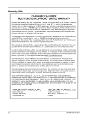
.... IMPORTANT: Take care not to light. OPERATION GUIDE 9-3 Maintenance 2 Lift the developer unit together with the toner container out of the machine. 3 Remove the drum unit from the metal registration roller. IMPORTANT: Do not place the drum unit on end. 9 5 Use a clean, lint free cloth to light for more... than five minutes. 4 Place the drum unit flat on a clean, level surface. Never expose the drum unit to clean dust and dirt away from the machine by...
.... IMPORTANT: Take care not to light. OPERATION GUIDE 9-3 Maintenance 2 Lift the developer unit together with the toner container out of the machine. 3 Remove the drum unit from the metal registration roller. IMPORTANT: Do not place the drum unit on end. 9 5 Use a clean, lint free cloth to light for more... than five minutes. 4 Place the drum unit flat on a clean, level surface. Never expose the drum unit to clean dust and dirt away from the machine by...
FS-1028MFP/1128MFP Operation Guide Rev-3
Page 346
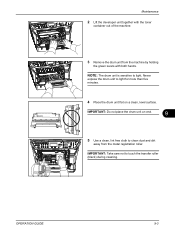
Maintenance 6 On the drum unit, slide the main charger cleaner (green) back and forth 2 or 3 times to clean the charger wire, then return it to its original position (CLEANER HOME ...POSITION ). After cleaning, make sure you restore the main charger cleaner to its home position. 7 When cleaning is complete, return the drum unit to the original position. 8 Return the developer unit to its position, aligning the guides at both ends with the slots in the machine. IMPORTANT: Remove the fixing tape on the...
Maintenance 6 On the drum unit, slide the main charger cleaner (green) back and forth 2 or 3 times to clean the charger wire, then return it to its original position (CLEANER HOME ...POSITION ). After cleaning, make sure you restore the main charger cleaner to its home position. 7 When cleaning is complete, return the drum unit to the original position. 8 Return the developer unit to its position, aligning the guides at both ends with the slots in the machine. IMPORTANT: Remove the fixing tape on the...
FS-1028MFP/1128MFP Operation Guide Rev-3
Page 349
... transportation of time, remove the power cord from the machine. 9 OPERATION GUIDE 9-7 Moving the Machine When you ship the machine, remove and pack the developer unit and drum unit in a plastic bag and ship them separately from the wall outlet. WARNING: If you move the machine: • Move it gently. • Keep it...
... transportation of time, remove the power cord from the machine. 9 OPERATION GUIDE 9-7 Moving the Machine When you ship the machine, remove and pack the developer unit and drum unit in a plastic bag and ship them separately from the wall outlet. WARNING: If you move the machine: • Move it gently. • Keep it...
FS-1028MFP/1128MFP Operation Guide Rev-3
Page 364
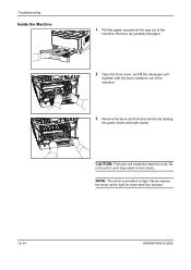
NOTE: The drum is hot. Remove any partially fed paper. 2 Open the front cover, and lift the developer unit together with the toner container out of the machine. Troubleshooting Inside the Machine 1 Pull the paper cassette all the way out of the machine. 3 Remove the drum unit from the machine by holding the green levers with both hands. Never expose the drum unit to light. CAUTION: The fuser unit inside the machine is sensitive to light for more than five minutes. 10-14 OPERATION GUIDE Do not touch it, as it may result in burn injury.
NOTE: The drum is hot. Remove any partially fed paper. 2 Open the front cover, and lift the developer unit together with the toner container out of the machine. Troubleshooting Inside the Machine 1 Pull the paper cassette all the way out of the machine. 3 Remove the drum unit from the machine by holding the green levers with both hands. Never expose the drum unit to light. CAUTION: The fuser unit inside the machine is sensitive to light for more than five minutes. 10-14 OPERATION GUIDE Do not touch it, as it may result in burn injury.
FS-1028MFP/1128MFP Operation Guide Rev-3
Page 365
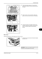
... paper jams of the rear cover. 1 Open the rear cover and remove the jammed paper by pulling it may result in the machine. 6 Insert the developer unit together with the slots in burn injury. 10-15 Do not touch it, as it out. The machine warms up and resumes printing. 10 Rear...
... paper jams of the rear cover. 1 Open the rear cover and remove the jammed paper by pulling it may result in the machine. 6 Insert the developer unit together with the slots in burn injury. 10-15 Do not touch it, as it out. The machine warms up and resumes printing. 10 Rear...
FS-1028MFP/1128MFP Quick Guide
Page 16
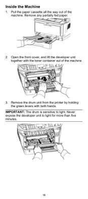
Remove the drum unit from the printer by holding the green levers with the toner container out of the machine. Inside the Machine 1. IMPORTANT: The drum is sensitive to light for more than five minutes. 16 Open the front cover, and lift the developer unit together with both hands. Pull the paper cassette all the way out of the machine. 3. Never expose the developer unit to light. Remove any partially fed paper. 2.
Remove the drum unit from the printer by holding the green levers with the toner container out of the machine. Inside the Machine 1. IMPORTANT: The drum is sensitive to light for more than five minutes. 16 Open the front cover, and lift the developer unit together with both hands. Pull the paper cassette all the way out of the machine. 3. Never expose the developer unit to light. Remove any partially fed paper. 2.
FS-1028MFP/1128MFP Quick Guide
Page 17
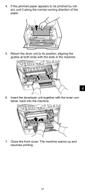
Insert the developer unit together with the slots in the machine. 4 6. If the jammed paper appears to its position, aligning the guides at both ends with the toner container, back into the machine. 7. Return the drum unit to be pinched by rollers, pull it along the normal running direction of the paper. 5. Close the front cover. The machine warms up and resumes printing. 17 4.
Insert the developer unit together with the slots in the machine. 4 6. If the jammed paper appears to its position, aligning the guides at both ends with the toner container, back into the machine. 7. Return the drum unit to be pinched by rollers, pull it along the normal running direction of the paper. 5. Close the front cover. The machine warms up and resumes printing. 17 4.
FS-1028MFP/1128MFP Quick Guide
Page 21
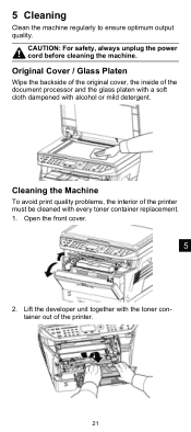
Lift the developer unit together with alcohol or mild detergent. Original Cover / Glass Platen Wipe the backside of the original cover, the inside of the document processor and the ...
Lift the developer unit together with alcohol or mild detergent. Original Cover / Glass Platen Wipe the backside of the original cover, the inside of the document processor and the ...

FS-1028MFP/1128MFP Quick Guide
Page 22
...the green levers with both hands. NOTE: The drum is sensitive to light for more than five minutes. 4. Never expose the developer unit to light. Remove the drum unit from the metal registration roller. IMPORTANT: Take care not to its original position (CLEANER HOME POSITION). 22 On the drum... unit, slide the charger cleaner (green) back and forth 2 or 3 times to clean the charger wire, then return it to touch the transfer...
...the green levers with both hands. NOTE: The drum is sensitive to light for more than five minutes. 4. Never expose the developer unit to light. Remove the drum unit from the metal registration roller. IMPORTANT: Take care not to its original position (CLEANER HOME POSITION). 22 On the drum... unit, slide the charger cleaner (green) back and forth 2 or 3 times to clean the charger wire, then return it to touch the transfer...

FS-1028MFP/1128MFP Quick Guide
Page 23
IMPORTANT: Remove the fixing tape on the charger cleaner before cleaning for the first time. Return the developer unit to the original position. 8. Then, close the front cover. 5 23 When cleaning is complete, return the drum unit to its home position. 7. After cleaning, make sure you restore the charger cleaner to its position, aligning the guides at both ends with the slots in the printer.
IMPORTANT: Remove the fixing tape on the charger cleaner before cleaning for the first time. Return the developer unit to the original position. 8. Then, close the front cover. 5 23 When cleaning is complete, return the drum unit to its home position. 7. After cleaning, make sure you restore the charger cleaner to its position, aligning the guides at both ends with the slots in the printer.
Service Manual
Page 12
...and Disassembly 1-5-1 Precautions for assembly and disassembly 1-5-1 (1) Precautions ...1-5-1 (2) Drum...1-5-1 (3) Toner ...1-5-1 (4) How to tell a genuine Kyocera Mita toner container 1-5-2 1-5-2 Outer covers ...1-5-3 (1) Detaching and refitting the left cover and right cover 1-5-3 1-5-3 Paper feed section ... and inverter PWB 1-5-27 1-5-5 Developing section...1-5-29 (1) Detaching and refitting the developing unit 1-5-29 1-5-6 Drum section...1-5-30 (1) Detaching and refitting the drum unit 1-5-30 (2) Detaching and refitting the main charger unit 1-5-31 1-5-7 Transfer/separation section ...
...and Disassembly 1-5-1 Precautions for assembly and disassembly 1-5-1 (1) Precautions ...1-5-1 (2) Drum...1-5-1 (3) Toner ...1-5-1 (4) How to tell a genuine Kyocera Mita toner container 1-5-2 1-5-2 Outer covers ...1-5-3 (1) Detaching and refitting the left cover and right cover 1-5-3 1-5-3 Paper feed section ... and inverter PWB 1-5-27 1-5-5 Developing section...1-5-29 (1) Detaching and refitting the developing unit 1-5-29 1-5-6 Drum section...1-5-30 (1) Detaching and refitting the drum unit 1-5-30 (2) Detaching and refitting the main charger unit 1-5-31 1-5-7 Transfer/separation section ...
Service Manual
Page 20
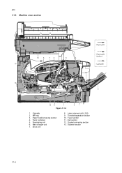
Cassette 2. Drum unit 8. Fuser section 11. Paper feed/conveying section 4. Transfer/separation section 10. Scanner section 1-1-6 Laser scanner unit (LSU) 9. Duplex/conveying section 13. MP tray 3. Main charger unit 7. Exit section 12. Toner container 5. Developing unit 6. 2JN 1-1-3 Machine cross section Paper path 13 8 76 5 4 Paper path (option) 11 Light path 10 2 12 9 1 3 Figure 1-1-3 1.
Cassette 2. Drum unit 8. Fuser section 11. Paper feed/conveying section 4. Transfer/separation section 10. Scanner section 1-1-6 Laser scanner unit (LSU) 9. Duplex/conveying section 13. MP tray 3. Main charger unit 7. Exit section 12. Toner container 5. Developing unit 6. 2JN 1-1-3 Machine cross section Paper path 13 8 76 5 4 Paper path (option) 11 Light path 10 2 12 9 1 3 Figure 1-1-3 1.

Service Manual
Page 30
... voltage Setting the voltage for the primary transfer Checking/clearing the drum drive time Performing drum refresh operation Initial setting for the developing unit Setting toner loading operation Checking the developing drive time Setting the fuser control temperature Checking the fuser temperature Initial setting* - 541/0/0/0 235/0/0/0/0/0/0 0/0/0/0/0 0 0 0/0 0/0 0/0 0/0 0 0/0/0/0/0 0/0 125/125/120 0 0 ... 2JN (2) Maintenance modes item list Section General Initialization Drive, paper feed, paper conveying and cooling system Optical High voltage Developing Fuser and cleaning Item No.
... voltage Setting the voltage for the primary transfer Checking/clearing the drum drive time Performing drum refresh operation Initial setting for the developing unit Setting toner loading operation Checking the developing drive time Setting the fuser control temperature Checking the fuser temperature Initial setting* - 541/0/0/0 235/0/0/0/0/0/0 0/0/0/0/0 0 0 0/0 0/0 0/0 0/0 0 0/0/0/0/0 0/0 125/125/120 0 0 ... 2JN (2) Maintenance modes item list Section General Initialization Drive, paper feed, paper conveying and cooling system Optical High voltage Developing Fuser and cleaning Item No.

Service Manual
Page 59
...page 2-4-4, page 1-5-29 and page 1-5-30) Method 1. Press the start key. Purpose To operate when installing the machine or replacing the developing unit. Select [INST MODE] using the cursor up /down keys and press the start key. 5. Display TIME(SEC) INST MODE Description ...Initial setting for selecting a maintenance item No. Turn the main power switch off and on . The screen for the developing unit Description Replenishes toner to the developing unit to a certain level from the toner container that has been installed. 2JN-2 Maintenance item No. Purpose To operate when...
...page 2-4-4, page 1-5-29 and page 1-5-30) Method 1. Press the start key. Purpose To operate when installing the machine or replacing the developing unit. Select [INST MODE] using the cursor up /down keys and press the start key. 5. Display TIME(SEC) INST MODE Description ...Initial setting for selecting a maintenance item No. Turn the main power switch off and on . The screen for the developing unit Description Replenishes toner to the developing unit to a certain level from the toner container that has been installed. 2JN-2 Maintenance item No. Purpose To operate when...

Service Manual
Page 60
... value is lower than the ratio defined by [PAGE] is set using the cursor left/right keys. U157 Checking the developing drive time Description Displays the developing drive time for selecting a maintenance item No. Display T7 MODE STEP1 PAGE STEP2 PAGE STEP3 PAGE STEP1 RATE STEP2 RATE ... printed pages assigned by [RATIO]. Setting 1. Description U144 Setting toner loading operation Description Sets toner loading operation after replacing the developing unit. 2JN-2 Maintenance item No. Display Description TIME(min) Developing drive time Completion Press the stop key.
... value is lower than the ratio defined by [PAGE] is set using the cursor left/right keys. U157 Checking the developing drive time Description Displays the developing drive time for selecting a maintenance item No. Display T7 MODE STEP1 PAGE STEP2 PAGE STEP3 PAGE STEP1 RATE STEP2 RATE ... printed pages assigned by [RATIO]. Setting 1. Description U144 Setting toner loading operation Description Sets toner loading operation after replacing the developing unit. 2JN-2 Maintenance item No. Display Description TIME(min) Developing drive time Completion Press the stop key.
Service Manual
Page 131
...the front cover and check that the drum unit and developing unit are correctly seated (See page 1-5-30 and 1-5-29). Replace the laser scanner unit (See page 1-5-17). Open the front cover and check that the drum unit and developing unit are correctly seated (See page 1-5-30 ...printout. Replace the high voltage PWB (See page 1-5-45). Defective laser scanner unit. minal M on the high voltage PWB. Replace the main charger unit (See page 1-5-31). DP DP connector Defective drum unit or developing unit. Poor contact of transfer bias terminal (spring) and transfer bias terminal T ...
...the front cover and check that the drum unit and developing unit are correctly seated (See page 1-5-30 and 1-5-29). Replace the laser scanner unit (See page 1-5-17). Open the front cover and check that the drum unit and developing unit are correctly seated (See page 1-5-30 ...printout. Replace the high voltage PWB (See page 1-5-45). Defective laser scanner unit. minal M on the high voltage PWB. Replace the main charger unit (See page 1-5-31). DP DP connector Defective drum unit or developing unit. Poor contact of transfer bias terminal (spring) and transfer bias terminal T ...
Service Manual
Page 132
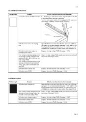
... the defects occur at regular intervals of 62.8 mm/2 1/2" (See page 2-4-3), the problem may be leaking from the developing unit or drum unit. Replace the developing unit (See page 1-5-29). Replace paper with rugged surface or dump tends to remove oil and debris. Replace the transfer roller... bush to cause dropouts. Defective transfer bias output. If the defects occur at regular intervals of electroconductive grease as required. Replace the developing unit or drum unit (See page 1-5-29 or 1-5-30). (5) Black horizontal streaks. Apply the grounding tab a small amount of 94 mm/3 11/16...
... the defects occur at regular intervals of 62.8 mm/2 1/2" (See page 2-4-3), the problem may be leaking from the developing unit or drum unit. Replace the developing unit (See page 1-5-29). Replace paper with rugged surface or dump tends to remove oil and debris. Replace the transfer roller... bush to cause dropouts. Defective transfer bias output. If the defects occur at regular intervals of electroconductive grease as required. Replace the developing unit or drum unit (See page 1-5-29 or 1-5-30). (5) Black horizontal streaks. Apply the grounding tab a small amount of 94 mm/3 11/16...

Service Manual
Page 133
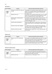
... debris. ABC 123 Defective potential on drum after printing means that satisfies the paper specification. Defective developing roller (developing unit). Defective developing roller (developing unit). Check procedures/corrective measures Replace paper with a new one that the cleaning blade (in the ...Check procedures/corrective measures Remove the drum unit (See page 1-5-30). A streak of oxide to conserve toner for check, replace the current developing unit in the drum unit) is not working properly. If a developing unit which is available for draft printing purpose...
... debris. ABC 123 Defective potential on drum after printing means that satisfies the paper specification. Defective developing roller (developing unit). Defective developing roller (developing unit). Check procedures/corrective measures Replace paper with a new one that the cleaning blade (in the ...Check procedures/corrective measures Remove the drum unit (See page 1-5-30). A streak of oxide to conserve toner for check, replace the current developing unit in the drum unit) is not working properly. If a developing unit which is available for draft printing purpose...

Service Manual
Page 134
...straight. Defective control PWB. Clean these areas and parts to remove toner. Print example Causes Defective polygon motor (laser scanner unit). This vertical line should be caused by continuously printing a low density page until the symptom has faded away. (10)...unit (See page 1-5-17). Replace the control PWB (See page 1-5-39). 1-4-16 Check procedures/corrective measures Dirty edges and back of the paper. Defective transfer roller. 2JN (9) Dirt on such parts as the paper chute guide, paper conveying paths, the bottom of the drum and developing unit, and the fuser unit...
...straight. Defective control PWB. Clean these areas and parts to remove toner. Print example Causes Defective polygon motor (laser scanner unit). This vertical line should be caused by continuously printing a low density page until the symptom has faded away. (10)...unit (See page 1-5-17). Replace the control PWB (See page 1-5-39). 1-4-16 Check procedures/corrective measures Dirty edges and back of the paper. Defective transfer roller. 2JN (9) Dirt on such parts as the paper chute guide, paper conveying paths, the bottom of the drum and developing unit, and the fuser unit...


