FS-1028MFP/1128MFP Operation Guide Rev-3
Page 15
... eyes and skin. • If you do happen to inhale toner, move to force open or destroy the toner container or the waste toner box. Do not attempt to a place with fresh air and gargle thoroughly with soap and water. If using the FS-1128MFP the main power switch is off the main power switch, but...
... eyes and skin. • If you do happen to inhale toner, move to force open or destroy the toner container or the waste toner box. Do not attempt to a place with fresh air and gargle thoroughly with soap and water. If using the FS-1128MFP the main power switch is off the main power switch, but...

FS-1028MFP/1128MFP Operation Guide Rev-3
Page 16
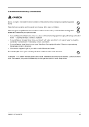
... your dealer or service representative. If the machine will be used for an extended period of temperature and humidity. xiv OPERATION GUIDE The collected toner container and waste toner box will not be recycled or disposed in a place where the temperature stays below 40ºC while avoiding sharp changes of time, remove the...
... your dealer or service representative. If the machine will be used for an extended period of temperature and humidity. xiv OPERATION GUIDE The collected toner container and waste toner box will not be recycled or disposed in a place where the temperature stays below 40ºC while avoiding sharp changes of time, remove the...
FS-1028MFP/1128MFP Operation Guide Rev-3
Page 347
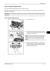
... the arrow and 9 pull out the toner container. Push the lock lever to the unlock position. Dangerous sparks may deteriorate output quality. Maintenance Toner Container Replacement When the message display displays Add toner, replace the toner. NOTE: Put the old toner container in order to incinerate the toner container or the waste toner box. CAUTION: Do not attempt...
... the arrow and 9 pull out the toner container. Push the lock lever to the unlock position. Dangerous sparks may deteriorate output quality. Maintenance Toner Container Replacement When the message display displays Add toner, replace the toner. NOTE: Put the old toner container in order to incinerate the toner container or the waste toner box. CAUTION: Do not attempt...

FS-1128MFP Fax Operation Guide Rev-3
Page 7
.... This machine may be avoided, change the direction the unit is a danger of this machine to the machine for Use • Loading Paper • Toner Container and Waste Toner Box Replacement • Clearing Paper Jams • Solving Malfunctions • Cleaning Installation Precautions Environment Avoid installing this machine in areas with poor telephone lines...
.... This machine may be avoided, change the direction the unit is a danger of this machine to the machine for Use • Loading Paper • Toner Container and Waste Toner Box Replacement • Clearing Paper Jams • Solving Malfunctions • Cleaning Installation Precautions Environment Avoid installing this machine in areas with poor telephone lines...
Service Manual
Page 128
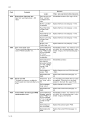
... the error is 0 (A/D value). Control PWB - Also check for continuity within the connector harness. Waste toner full The waste toner sensor has detected that the waste toner reservoir (drum unit) is full. Replace the waste toner sensor. installed incorrectly. Replace the operation panel PWB. heater lamp wire. Poor contact in the fuser ... triggered. Fuser thermistor installed incorrectly. Defective power source PWB. If none, remedy or replace the harness (See page 15-39). Waste toner reservoir (drum unit) is full. Broken fuser ther-
... the error is 0 (A/D value). Control PWB - Also check for continuity within the connector harness. Waste toner full The waste toner sensor has detected that the waste toner reservoir (drum unit) is full. Replace the waste toner sensor. installed incorrectly. Replace the operation panel PWB. heater lamp wire. Poor contact in the fuser ... triggered. Fuser thermistor installed incorrectly. Defective power source PWB. If none, remedy or replace the harness (See page 15-39). Waste toner reservoir (drum unit) is full. Broken fuser ther-

Service Manual
Page 221
... This lowers the electrical conductivity of toner which is residual after the development process. This is collected at the output end of the sweep roller and sent back to the toner container, into the waste toner reservoir. The waste toner is necessary to erase any residual ...positive charge, ready to the ground. 1 Main frame Waste toner reservoir 3 2 Drum unit Figure 2-1-19 Cleaning section (1) Eraser lamp (PWB...
... This lowers the electrical conductivity of toner which is residual after the development process. This is collected at the output end of the sweep roller and sent back to the toner container, into the waste toner reservoir. The waste toner is necessary to erase any residual ...positive charge, ready to the ground. 1 Main frame Waste toner reservoir 3 2 Drum unit Figure 2-1-19 Cleaning section (1) Eraser lamp (PWB...

Service Manual
Page 231
... source to the fuser heater lamp when the heat roller reaches extremely high temperature. 2-2-3 Toner sensor Detects the quantity of paper in a toner container. 10. Main power switch Turns ON/OFF the AC power source. 2. Waste toner sensor Detects when the waste toner reservoir (Drum unit) is opened. 3. Registration sensor Detects the timing of paper on...
... source to the fuser heater lamp when the heat roller reaches extremely high temperature. 2-2-3 Toner sensor Detects the quantity of paper in a toner container. 10. Main power switch Turns ON/OFF the AC power source. 2. Waste toner sensor Detects when the waste toner reservoir (Drum unit) is opened. 3. Registration sensor Detects the timing of paper on...

Service Manual
Page 241
...THERM 17 +24V3 18 SGND 19 SEPA YC24 1 +3.3V1 Connected 2 TNFULL to the waste 3 SGND toner sensor YC25 Connected to the high voltage PWB 1 +24V2 2 +24V2 3 PGND 4 PGND YC26 Connected to the toner sensor YC27 Connected to the right cooling fan motor 1 +3.3V1 2 TEMPTY 3 SGND... control signal O PWM Main charger output control signal O 0/3.3 V DC Transfer bias output signal: On/Off I Analog Cassette switch: On/Off I 0/3.3 V DC Waste toner full detection signal -- Ground I 24 V DC I 24 V DC --- 24 V DC power source 24 V DC power source Ground Ground O 3.3 V DC I 0/3.3 V...
...THERM 17 +24V3 18 SGND 19 SEPA YC24 1 +3.3V1 Connected 2 TNFULL to the waste 3 SGND toner sensor YC25 Connected to the high voltage PWB 1 +24V2 2 +24V2 3 PGND 4 PGND YC26 Connected to the toner sensor YC27 Connected to the right cooling fan motor 1 +3.3V1 2 TEMPTY 3 SGND... control signal O PWM Main charger output control signal O 0/3.3 V DC Transfer bias output signal: On/Off I Analog Cassette switch: On/Off I 0/3.3 V DC Waste toner full detection signal -- Ground I 24 V DC I 24 V DC --- 24 V DC power source 24 V DC power source Ground Ground O 3.3 V DC I 0/3.3 V...

Service Manual
Page 248
... 6 DLPDRN +24V3 FEDDRN 1 2 1 2 11 22 33 3 4 1 2 1 2 1 2 3 4 1 2 YC20 YC29 YC21 YC27 YC28 Control PWB [2/2] YC30 YC13 4 3 2 1 4 3 2 1 +3.3V1 RFCLK RFDATA GND 4 3 2 1 4 3 2 1 1 1 +3.3V1 YC26 2 2 TEMPTY 3 3 GND Toner sensor 11 22 33 44 55 66 11 22 33 44 55 +24V1 1 1 SGND 2 2 FAN 3 3 THERM 4 4 +3.3V1 5 5 HEATN 6 6 SLEEP 7 7 ZCROSS 8 8 +24V2 9 9 +24V2 10 10 PGND...2 2 LIVE YC101 1 1 NEUTRAL Main power switch AC input 1 2 3 4 5 6 +24V3 GND PFSI PFSO PFSEL +3.3V1 Main frame 1 1 +3.3V1 YC24 2 2 TNFULL 3 3 GND Waste toner sensor Paper feeder 8 7 Optional paper feeder
... 6 DLPDRN +24V3 FEDDRN 1 2 1 2 11 22 33 3 4 1 2 1 2 1 2 3 4 1 2 YC20 YC29 YC21 YC27 YC28 Control PWB [2/2] YC30 YC13 4 3 2 1 4 3 2 1 +3.3V1 RFCLK RFDATA GND 4 3 2 1 4 3 2 1 1 1 +3.3V1 YC26 2 2 TEMPTY 3 3 GND Toner sensor 11 22 33 44 55 66 11 22 33 44 55 +24V1 1 1 SGND 2 2 FAN 3 3 THERM 4 4 +3.3V1 5 5 HEATN 6 6 SLEEP 7 7 ZCROSS 8 8 +24V2 9 9 +24V2 10 10 PGND...2 2 LIVE YC101 1 1 NEUTRAL Main power switch AC input 1 2 3 4 5 6 +24V3 GND PFSI PFSO PFSEL +3.3V1 Main frame 1 1 +3.3V1 YC24 2 2 TNFULL 3 3 GND Waste toner sensor Paper feeder 8 7 Optional paper feeder


