
User Guide
Page 2
...net if needed, or tying long hair up in accordance with these precautions a part of the job descriptio n for operation of the Kodak i800 Series Scanners or any machinery. These include, but are designed to provide reasonable protection against harmful interference when the equipment is likely to cause harmful .... WARNING: Dangerous voltage. July 2003 1 ElectroMagnetic Compatibility Statements European Union This is a Class A product. Safety and Installation Information for the Kodak i800 Series Scanners IMPORTANT: Equipment shall be required to part 15 of the FCC rules.
...net if needed, or tying long hair up in accordance with these precautions a part of the job descriptio n for operation of the Kodak i800 Series Scanners or any machinery. These include, but are designed to provide reasonable protection against harmful interference when the equipment is likely to cause harmful .... WARNING: Dangerous voltage. July 2003 1 ElectroMagnetic Compatibility Statements European Union This is a Class A product. Safety and Installation Information for the Kodak i800 Series Scanners IMPORTANT: Equipment shall be required to part 15 of the FCC rules.
User Guide
Page 4
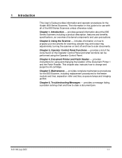
... July 2003 1-1 1 Introduction This User's Guide provides information and operator procedures for use with all of the i800 Series Scanners unless otherwise noted. The information in this guide is for the Kodak i800 Series Scanners. Chapter 4, Document Printer and Patch Reader provides instructions for the feeder module and tires, separation roller and...
... July 2003 1-1 1 Introduction This User's Guide provides information and operator procedures for use with all of the i800 Series Scanners unless otherwise noted. The information in this guide is for the Kodak i800 Series Scanners. Chapter 4, Document Printer and Patch Reader provides instructions for the feeder module and tires, separation roller and...
User Guide
Page 5
... simplify service and minimize downtime • Image address with Patch Reader support • Document Printer 1 imprinting on the Kodak i800 Series Scanners. • Simultaneous output of image output resolutions in iThresholding, Adaptive Threshold Processing (ATP), image compression, despeckle, error diffusion...; Color on-the-fly • Accepts custom color tables • A wide variety of color and bi-tonal images (i820 and i840 scanners only) • SurePath paper handling, featuring: - 1,000-sheet QuickSet elevator that produce high quality production images. An adjustable...
... simplify service and minimize downtime • Image address with Patch Reader support • Document Printer 1 imprinting on the Kodak i800 Series Scanners. • Simultaneous output of image output resolutions in iThresholding, Adaptive Threshold Processing (ATP), image compression, despeckle, error diffusion...; Color on-the-fly • Accepts custom color tables • A wide variety of color and bi-tonal images (i820 and i840 scanners only) • SurePath paper handling, featuring: - 1,000-sheet QuickSet elevator that produce high quality production images. An adjustable...
User Guide
Page 6
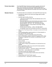
...*, 200, 150, 100 300, 200 A-61169 July 2003 1-3 Standard configurations Four models of the Kodak i800 Series Scanners are available: • Kodak i810 Scanner (bi-tonal) provides bi-tonal scanning with throughput speeds up to 120 ppm • Kodak i820 Scanner provides both color and bi-tonal scanning simultaneously with throughput speeds up to 120...
...*, 200, 150, 100 300, 200 A-61169 July 2003 1-3 Standard configurations Four models of the Kodak i800 Series Scanners are available: • Kodak i810 Scanner (bi-tonal) provides bi-tonal scanning with throughput speeds up to 120 ppm • Kodak i820 Scanner provides both color and bi-tonal scanning simultaneously with throughput speeds up to 120...
User Guide
Page 7
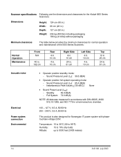
... 100 - 127 V, 6.5 A, 50/60 Hz 200 - 240 V, 3.5 A, 50/60 Hz This product is also designed for normal operation and maintenance of the i800 Series Scanners: Normal Operation Maintenance Front N/A 40 in. 102 cm Rear 4 in. 10 cm 4 in. 10 cm Right Side 4 in. 10 cm 24 in. 61 cm Left...(59 to 95°F) Humidity: 15 to 76% (dry bulb) Altitude: up to 8000 feet (2438 meters) 1-4 A-61169 July 2003 Scanner specifications Following are the dimensions and clearances for the Kodak i800 Series Scanners: Dimensions Height: Width: Depth: Weight: 124 cm (49 in.) 66 cm (26 in.) 127 cm (50 in . 61 cm...
... 100 - 127 V, 6.5 A, 50/60 Hz 200 - 240 V, 3.5 A, 50/60 Hz This product is also designed for normal operation and maintenance of the i800 Series Scanners: Normal Operation Maintenance Front N/A 40 in. 102 cm Rear 4 in. 10 cm 4 in. 10 cm Right Side 4 in. 10 cm 24 in. 61 cm Left...(59 to 95°F) Humidity: 15 to 76% (dry bulb) Altitude: up to 8000 feet (2438 meters) 1-4 A-61169 July 2003 Scanner specifications Following are the dimensions and clearances for the Kodak i800 Series Scanners: Dimensions Height: Width: Depth: Weight: 124 cm (49 in.) 66 cm (26 in.) 127 cm (50 in . 61 cm...
User Guide
Page 8
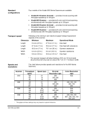
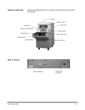
External components See the illustration below for the location of the external components of scanner SCSI Connector Power cord connector A-61169 July 2003 1-5 Output tray Operator control panel Side guides Elevator tray Feed module Top cover Swing out door Bi-fold door Power switch Gap release lever Feeder extensions Back of the scanner.
External components See the illustration below for the location of the external components of scanner SCSI Connector Power cord connector A-61169 July 2003 1-5 Output tray Operator control panel Side guides Elevator tray Feed module Top cover Swing out door Bi-fold door Power switch Gap release lever Feeder extensions Back of the scanner.

User Guide
Page 9
...regulated due to meet worldwide environmental requirements. • Guidelines are available for reuse or recycling. • The Kodak i800 Series Scanners contain lead in the circuit boards and mercury in the lamps. Disposal of consumable items that are replaced during ...maintenance or service; Environmental information and equipment disposal • The Kodak i800 Series Scanners are designed to environmental considerations. For disposal or recycling information, please contact your local authorities or visit the Electronics...
...regulated due to meet worldwide environmental requirements. • Guidelines are available for reuse or recycling. • The Kodak i800 Series Scanners contain lead in the circuit boards and mercury in the lamps. Disposal of consumable items that are replaced during ...maintenance or service; Environmental information and equipment disposal • The Kodak i800 Series Scanners are designed to environmental considerations. For disposal or recycling information, please contact your local authorities or visit the Electronics...
User Guide
Page 10
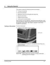
...performed using multi-feed detection, setting the elevator level, etc. 2 Using the Scanner This chapter provides the following operational procedures: • Turning on the Operator Control Panel, the scanner is displayed on the scanner • Document preparation • Adjusting the input tray, side guides and output ... keys, using the Operator Control Panel. A-61169 July 2003 2-1 Turning on the scanner To turn on the scanner: • Toggle the power switch to its Ready state before powering-up the scanner to the On position. On/Off switch When the menu bar is Ready.
...performed using multi-feed detection, setting the elevator level, etc. 2 Using the Scanner This chapter provides the following operational procedures: • Turning on the Operator Control Panel, the scanner is displayed on the scanner • Document preparation • Adjusting the input tray, side guides and output ... keys, using the Operator Control Panel. A-61169 July 2003 2-1 Turning on the scanner To turn on the scanner: • Toggle the power switch to its Ready state before powering-up the scanner to the On position. On/Off switch When the menu bar is Ready.
User Guide
Page 11
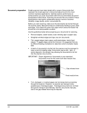
...edges (steno paper, perforated edges, tractor feed edges). Best performance is obtained by feeding a good, clean lead edge. Optimal scanner performance is achieved when you start scanning, make sure the documents can transport every possible type of the paper which orientation feeds ... damaged paper. Use the guidelines below . However, no scanner can be trimmed, it is suggested that you try different feeding orientations to be in the most common business applications. Document preparation Kodak scanners have a common leading edge. IMPORTANT: Proper alignment of document...
...edges (steno paper, perforated edges, tractor feed edges). Best performance is obtained by feeding a good, clean lead edge. Optimal scanner performance is achieved when you start scanning, make sure the documents can transport every possible type of the paper which orientation feeds ... damaged paper. Use the guidelines below . However, no scanner can be trimmed, it is suggested that you try different feeding orientations to be in the most common business applications. Document preparation Kodak scanners have a common leading edge. IMPORTANT: Proper alignment of document...
User Guide
Page 15
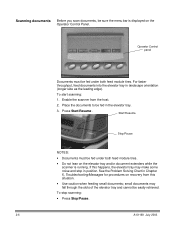
.... 3. Scanning documents Before you scan documents, be sure the menu bar is displayed on the elevator tray and/or document extenders while the scanner is running. Enable the scanner from this happens, the elevator tray may fall through the slots of the elevator tray and cannot be fed in position. See the...
.... 3. Scanning documents Before you scan documents, be sure the menu bar is displayed on the elevator tray and/or document extenders while the scanner is running. Enable the scanner from this happens, the elevator tray may fall through the slots of the elevator tray and cannot be fed in position. See the...
User Guide
Page 17
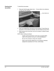
... (.030 inches). 2-8 A-61169 July 2003 Gap release lever 2. NOTE: Before feeding envelopes: − Disable multi-feed detection via the host or programmable button (if the scanner is set up for multi-feed detection.) − Be sure the envelope is empty and unsealed. − When using the gap release lever, the maximum...
... (.030 inches). 2-8 A-61169 July 2003 Gap release lever 2. NOTE: Before feeding envelopes: − Disable multi-feed detection via the host or programmable button (if the scanner is set up for multi-feed detection.) − Be sure the envelope is empty and unsealed. − When using the gap release lever, the maximum...

User Guide
Page 18
This chapter provides procedures and information for: • Enabling and disabling the scanner • Control Panel functions overview • Navigating through the functions on the Control Panel menu • Accessing information • Lowering ... Changing the display contrast − Changing the SCSI ID − Changing the SCSI termination − Setting the elevator tray position • Calibrating the scanner • Jogging the transport • Programmable key assignments A-61169 July 2003 3-1 3 Operator Control Panel Functions There are a variety of functions available from...
This chapter provides procedures and information for: • Enabling and disabling the scanner • Control Panel functions overview • Navigating through the functions on the Control Panel menu • Accessing information • Lowering ... Changing the display contrast − Changing the SCSI ID − Changing the SCSI termination − Setting the elevator tray position • Calibrating the scanner • Jogging the transport • Programmable key assignments A-61169 July 2003 3-1 3 Operator Control Panel Functions There are a variety of functions available from...
User Guide
Page 19
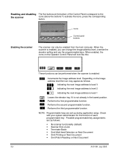
...the third programmable function. Check with your system administrator for the function of the Control Panel correspond to the the scanner icons above the buttons To activate the icons, press the corresponding button. Performs the second programmable function. Possible programmable key... assignments are set-up during application setup. Icons Control panel buttons Enabling the scanner The scanner can be enabled from the host computer. NOTE: Programmable keys are as follows: indicating the next image address is level...
...the third programmable function. Check with your system administrator for the function of the Control Panel correspond to the the scanner icons above the buttons To activate the icons, press the corresponding button. Performs the second programmable function. Possible programmable key... assignments are set-up during application setup. Icons Control panel buttons Enabling the scanner The scanner can be enabled from the host computer. NOTE: Programmable keys are as follows: indicating the next image address is level...
User Guide
Page 20
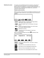
...displayed. Lowers the elevator tray if it is disabled. Temporarily turns on and disabled, the following icons will be performed when the scanner is not already in the lowest position. Moves right to help clear a document jam. Moves left arrow). When the Diagnostics Settings...disabled, you to one of -job function is assigned to perform additional functions. Displays information: including the last image address, meter values, scanner serial number. This button is referred to the next selectable item (left to as Return. Moves down arrow). 3-3 Moves up to the...
...displayed. Lowers the elevator tray if it is disabled. Temporarily turns on and disabled, the following icons will be performed when the scanner is not already in the lowest position. Moves right to help clear a document jam. Moves left arrow). When the Diagnostics Settings...disabled, you to one of -job function is assigned to perform additional functions. Displays information: including the last image address, meter values, scanner serial number. This button is referred to the next selectable item (left to as Return. Moves down arrow). 3-3 Moves up to the...
User Guide
Page 22
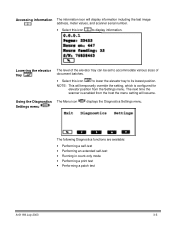
...; Performing a print test • Performing a patch test A-61169 July 2003 3-5 Accessing information The information icon will resume. The next time the scanner is configured for elevator position from the host the menu setting will display information including the last image address, meter values, and... scanner serial number. • Select this icon to lower the elevator tray to display information. Lowering the elevator tray The level ...
...; Performing a print test • Performing a patch test A-61169 July 2003 3-5 Accessing information The information icon will resume. The next time the scanner is configured for elevator position from the host the menu setting will display information including the last image address, meter values, and... scanner serial number. • Select this icon to lower the elevator tray to display information. Lowering the elevator tray The level ...

User Guide
Page 23
.... 4. You may want to the Diagnostics function. 3. Place the documents in count-only mode: 1. Select the Diagnostics Settings menu icon. 2. The scanner will run in the elevator tray. 5. the extended self-test is powered-up; To perform a self-test or extended self-test: 1. Use the... Settings menu icon. 2. To run the self-test and report the results on the scanner. Select Return. Running in count-only mode 4. The self-test is the same test performed when the scanner is a more thorough test. Press Start/Resume . Performing a self-test or extended self...
.... 4. You may want to the Diagnostics function. 3. Place the documents in count-only mode: 1. Select the Diagnostics Settings menu icon. 2. The scanner will run in the elevator tray. 5. the extended self-test is powered-up; To perform a self-test or extended self-test: 1. Use the... Settings menu icon. 2. To run the self-test and report the results on the scanner. Select Return. Running in count-only mode 4. The self-test is the same test performed when the scanner is a more thorough test. Press Start/Resume . Performing a self-test or extended self...
User Guide
Page 25
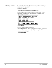
Select Return. 5. When the documents have been scanned, the document count and number of patch types recognized by the scanner will be displayed. 7. Press Stop/Pause. 3-8 A-61169 July 2003 To perform a patch test: 1. Use the right or left arrow to navigate to verify that your ...
Select Return. 5. When the documents have been scanned, the document count and number of patch types recognized by the scanner will be displayed. 7. Press Stop/Pause. 3-8 A-61169 July 2003 To perform a patch test: 1. Use the right or left arrow to navigate to verify that your ...
User Guide
Page 27
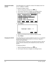
...the display contrast This setting allows you to adjust the contrast of the display screen from 0 to do so by your integrator or Kodak Field Representative. Select Return. Select the Diagnostics Settings menu icon. 2. Select the Diagnostics Settings menu icon. 2. Use the up and ...completed the self-test, reboot the host PC. If the SCSI ID has been changed unless directed to 4. 0 = lightest, 4 = darkest. After the scanner has been powered up and down arrow to select Change Display Contrast. 4. Use the down arrows...
...the display contrast This setting allows you to adjust the contrast of the display screen from 0 to do so by your integrator or Kodak Field Representative. Select Return. Select the Diagnostics Settings menu icon. 2. Select the Diagnostics Settings menu icon. 2. Use the up and ...completed the self-test, reboot the host PC. If the SCSI ID has been changed unless directed to 4. 0 = lightest, 4 = darkest. After the scanner has been powered up and down arrow to select Change Display Contrast. 4. Use the down arrows...
User Guide
Page 28
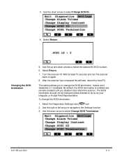
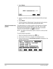
... Change SCSI ID. 4. Select the Diagnostics Settings menu icon. 2. Changing the SCSI termination 5. Wait at least 10 seconds and turn the scanner back on again. 8. To change the SCSI termination. A-61169 July 2003 3-11 The SCSI termination should not be changed unless directed to... by your integrator or Kodak Field Representative. Select Return. Use the down arrows to select Change SCSI Termination. Turn the scanner off. After the scanner has completed the self-test, reboot the host PC. This setting allows you disable it and reboot the scanner. Use the down arrow...
... Change SCSI ID. 4. Select the Diagnostics Settings menu icon. 2. Changing the SCSI termination 5. Wait at least 10 seconds and turn the scanner back on again. 8. To change the SCSI termination. A-61169 July 2003 3-11 The SCSI termination should not be changed unless directed to... by your integrator or Kodak Field Representative. Select Return. Use the down arrows to select Change SCSI Termination. Turn the scanner off. After the scanner has completed the self-test, reboot the host PC. This setting allows you disable it and reboot the scanner. Use the down arrow...
User Guide
Page 29
Wait at least 10 seconds and turn the scanner back on the Operator Control Panel. 3-12 A-61169 July 2003 To set to select the desired SCSI termination setting. 6. Press the down arrows to accommodate ...25-, 250-, 500-, 750- 4. Use the up and down arrow until Set elevator position is selected. Turn the scanner off. or 1000documents (20-lb bond paper). The position will take effect. Select the Diagnostics Settings menu icon. 2. Use the right or left arrow to...
Wait at least 10 seconds and turn the scanner back on the Operator Control Panel. 3-12 A-61169 July 2003 To set to select the desired SCSI termination setting. 6. Press the down arrows to accommodate ...25-, 250-, 500-, 750- 4. Use the up and down arrow until Set elevator position is selected. Turn the scanner off. or 1000documents (20-lb bond paper). The position will take effect. Select the Diagnostics Settings menu icon. 2. Use the right or left arrow to...


