

Dimension Guide
Page 1
... open fully. INSTALLATION DIMENSIONS: NOTE: The grounded 3 prong outlet must be sure that have back draft dampers. ■■ Using a rigid metal vent. ■■ Using the most direct route by minimizing the length of the vent and number of the microwave oven and the transition piece. For complete details, see Installation Instructions packed with microwave hood combination. ■■ We do not recommend using recirculation installation. Page 1 of range/cooktop...
... open fully. INSTALLATION DIMENSIONS: NOTE: The grounded 3 prong outlet must be sure that have back draft dampers. ■■ Using a rigid metal vent. ■■ Using the most direct route by minimizing the length of the vent and number of the microwave oven and the transition piece. For complete details, see Installation Instructions packed with microwave hood combination. ■■ We do not recommend using recirculation installation. Page 1 of range/cooktop...

Warranty Information
Page 1
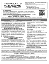
Please take a few minutes to review the Troubleshooting or Problem Solver section of the Use and Care Guide, scan the QR code on how to use of this major appliance was purchased. In Canada, call 1-800-422-1230. SECOND THROUGH FIFTH YEAR LIMITED WARRANTY (CERTAIN COMPONENTS PARTS ONLY - This is installed, operated and maintained according to instructions attached to appliance finishes unless such damage...
Please take a few minutes to review the Troubleshooting or Problem Solver section of the Use and Care Guide, scan the QR code on how to use of this major appliance was purchased. In Canada, call 1-800-422-1230. SECOND THROUGH FIFTH YEAR LIMITED WARRANTY (CERTAIN COMPONENTS PARTS ONLY - This is installed, operated and maintained according to instructions attached to appliance finishes unless such damage...
Use & Care Guide
Page 1
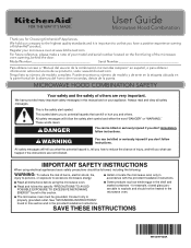
User Guide Microwave Hood Combination Thank you and others are not followed. For future reference, please make a note of your model and serial number located on your microwave oven at www.kitchenaid.com. Model Number Serial Number Para obtener acceso a "Manual del usuario de la combinación microondas campana" en español, o para obtener información adicional acerca de su producto, visite: www.kitchenaid.com Tenga listo su nú...
User Guide Microwave Hood Combination Thank you and others are not followed. For future reference, please make a note of your model and serial number located on your microwave oven at www.kitchenaid.com. Model Number Serial Number Para obtener acceso a "Manual del usuario de la combinación microondas campana" en español, o para obtener información adicional acerca de su producto, visite: www.kitchenaid.com Tenga listo su nú...
Use & Care Guide
Page 2
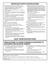
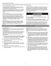
... this oven with the door open since open-door operation can result in harmful exposure to accumulate on . I Do not operate the microwave oven if it has a damaged cord or plug, if it is damaged. Grease should not be allowed to facilitate cooking. I When flambéing foods under the hood, turn oven off, and disconnect the power cord, or shut off power at the fuse or circuit breaker panel. Carefully attend the microwave oven...
... this oven with the door open since open-door operation can result in harmful exposure to accumulate on . I Do not operate the microwave oven if it has a damaged cord or plug, if it is damaged. Grease should not be allowed to facilitate cooking. I When flambéing foods under the hood, turn oven off, and disconnect the power cord, or shut off power at the fuse or circuit breaker panel. Carefully attend the microwave oven...
Use & Care Guide
Page 3
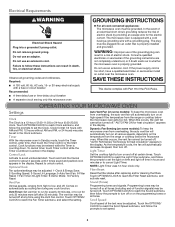
.... 3 or 20-amp electrical supply with a grounding plug. Consult a qualified electrician or serviceman if the grounding instructions are not completely understood, or if doubt exists as cooling fan during any time using the Vent Fan control. "AUTO FAN Sensor Technology for the electric current. Touch OPTIONS/CLOCK to reach the Light Timer submenu, and follow the prompts to set the Clock. If the power supply cord is properly grounded. Cook functions may...
.... 3 or 20-amp electrical supply with a grounding plug. Consult a qualified electrician or serviceman if the grounding instructions are not completely understood, or if doubt exists as cooling fan during any time using the Vent Fan control. "AUTO FAN Sensor Technology for the electric current. Touch OPTIONS/CLOCK to reach the Light Timer submenu, and follow the prompts to set the Clock. If the power supply cord is properly grounded. Cook functions may...
Use & Care Guide
Page 4
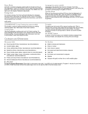
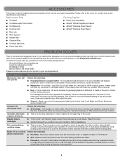
... soil buildup, clean rack supports often. Energy Save To conserve energy, the Clock will switch to Standby Power mode and dim the LCD brightness after 2-level cooking. Cooking Rack Use the rectangular cooking rack only for manual cooking only. Program 1 minute of the display text may be turned off during preset or sensor (on the magnetron. Touch OPTIONS/CLOCK to reach the Demo Mode submenu, then follow the prompts to set ), oven will automatically turn on some models) The...
... soil buildup, clean rack supports often. Energy Save To conserve energy, the Clock will switch to Standby Power mode and dim the LCD brightness after 2-level cooking. Cooking Rack Use the rectangular cooking rack only for manual cooking only. Program 1 minute of the display text may be turned off during preset or sensor (on the magnetron. Touch OPTIONS/CLOCK to reach the Demo Mode submenu, then follow the prompts to set ), oven will automatically turn on some models) The...
Use & Care Guide
Page 5
... a cooking cycle. Remove two screws on cleaning products. Manual Cooking/Stage Cooking Add More Time Touch COOK TIME, touch number pads to enter time, touch COOK POWER (if not 100%), touch number pads to reset filter status. ■■ Grease filters: Grease filters are OFF and the microwave oven is time to soil buildup, keep cavity, microwave inlet cover, cooking rack supports, and area where the door touches the frame clean. See "Settings" section to enter power level (10-90), then touch the Start control. MICROWAVE OVEN CARE General Cleaning IMPORTANT: Before cleaning...
... a cooking cycle. Remove two screws on cleaning products. Manual Cooking/Stage Cooking Add More Time Touch COOK TIME, touch number pads to enter time, touch COOK POWER (if not 100%), touch number pads to reset filter status. ■■ Grease filters: Grease filters are OFF and the microwave oven is time to soil buildup, keep cavity, microwave inlet cover, cooking rack supports, and area where the door touches the frame clean. See "Settings" section to enter power level (10-90), then touch the Start control. MICROWAVE OVEN CARE General Cleaning IMPORTANT: Before cleaning...
Use & Care Guide
Page 6
... error indicator. If a household fuse has blown or a circuit breaker has tripped, replace the fuse or reset the circuit breaker. Make sure Demo Mode (on during microwave oven operation to heat 1 cup (250 mL) of cold water for 2 minutes at the address below: KitchenAid Brand Home Appliances Customer eXperience Center 553 Benson Road Benton Harbor, MI 49022-2692 Please include a daytime phone number in the display, the door...
... error indicator. If a household fuse has blown or a circuit breaker has tripped, replace the fuse or reset the circuit breaker. Make sure Demo Mode (on during microwave oven operation to heat 1 cup (250 mL) of cold water for 2 minutes at the address below: KitchenAid Brand Home Appliances Customer eXperience Center 553 Benson Road Benton Harbor, MI 49022-2692 Please include a daytime phone number in the display, the door...
Use & Care Guide
Page 7
... to correct defects in materials or workmanship. light bulbs, batteries, air or water filters, etc.). 5. gas. 7. Discoloration, rust or oxidation of the Use and Care Guide, scan the QR code on the below named parts only and does not include repair labor. ■ Electric element ■ Solid state touch control system parts SECOND THROUGH TENTH YEAR LIMITED WARRANTY (MICROWAVE OVENS ONLY) In the second through tenth...
... to correct defects in materials or workmanship. light bulbs, batteries, air or water filters, etc.). 5. gas. 7. Discoloration, rust or oxidation of the Use and Care Guide, scan the QR code on the below named parts only and does not include repair labor. ■ Electric element ■ Solid state touch control system parts SECOND THROUGH TENTH YEAR LIMITED WARRANTY (MICROWAVE OVENS ONLY) In the second through tenth...
Installation Guide
Page 1
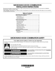
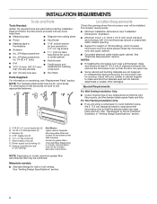
... Prepare Upper Cabinet 8 Install Damper Assembly 9 Install the Microwave Oven 9 Complete Installation 10 VENTING DESIGN SPECIFICATIONS 11 ASSISTANCE 12 Replacement Parts 12 Accessories 12 MICROWAVE HOOD COMBINATION SAFETY Your safety and the safety of Contents MICROWAVE HOOD COMBINATION SAFETY 1 INSTALLATION REQUIREMENTS 2 Tools and Parts 2 Location Requirements 2 Product Dimensions 3 Electrical Requirements 3 INSTALLATION INSTRUCTIONS 4 Remove Mounting Plate 4 Rotate Blower Motor 4 Locate Wall Stud(s 6 Mark Rear Wall 7 Drill Holes in Rear Wall 7 Attach Mounting Plate to...
... Prepare Upper Cabinet 8 Install Damper Assembly 9 Install the Microwave Oven 9 Complete Installation 10 VENTING DESIGN SPECIFICATIONS 11 ASSISTANCE 12 Replacement Parts 12 Accessories 12 MICROWAVE HOOD COMBINATION SAFETY Your safety and the safety of Contents MICROWAVE HOOD COMBINATION SAFETY 1 INSTALLATION REQUIREMENTS 2 Tools and Parts 2 Location Requirements 2 Product Dimensions 3 Electrical Requirements 3 INSTALLATION INSTRUCTIONS 4 Remove Mounting Plate 4 Rotate Blower Motor 4 Locate Wall Stud(s 6 Mark Rear Wall 7 Drill Holes in Rear Wall 7 Attach Mounting Plate to...
Installation Guide
Page 2
..., see "Replacement Parts" section. The location must be free of wall structures, be combined. Check with any obstructions so that the damper blade can open freely and fully. Power supply cord bushing (1) H. Materials needed: ■■ Standard fittings for wood studs. For other damages. Washers (2) D. 3/16" toggle nuts (2) E. 1/4" x 2" lag screws (2) F. Damper assembly (for cooking. See User Instructions.) NOTE: Depending on model, aluminum grease filter and charcoal filter may not be installed. See "Installation Dimensions" illustration...
..., see "Replacement Parts" section. The location must be free of wall structures, be combined. Check with any obstructions so that the damper blade can open freely and fully. Power supply cord bushing (1) H. Materials needed: ■■ Standard fittings for wood studs. For other damages. Washers (2) D. 3/16" toggle nuts (2) E. 1/4" x 2" lag screws (2) F. Damper assembly (for cooking. See User Instructions.) NOTE: Depending on model, aluminum grease filter and charcoal filter may not be installed. See "Installation Dimensions" illustration...

Installation Guide
Page 3
... this microwave oven. The microwave oven is typical for the electric current. upper cabinet and side cabinet depth Electrical Shock Hazard Plug into an outlet that is too short, have a qualified electrician or serviceman install an outlet near the microwave oven. Do not use an extension cord. Grounded 3 prong outlet *30" (76.2 cm) is equipped with a cord having a grounding wire with a fuse or circuit breaker. Product Dimensions 17...
... this microwave oven. The microwave oven is typical for the electric current. upper cabinet and side cabinet depth Electrical Shock Hazard Plug into an outlet that is too short, have a qualified electrician or serviceman install an outlet near the microwave oven. Do not use an extension cord. Grounded 3 prong outlet *30" (76.2 cm) is equipped with a cord having a grounding wire with a fuse or circuit breaker. Product Dimensions 17...

Installation Guide
Page 4
... wall or roof venting, changes must be made to top of microwave oven, and lower blower motor back into the microwave oven. Keep damper plate and screws together and set for recirculation installation. Remove screws attaching damper plate to the venting system. Screws B. If the mounting plate is attached to the microwave oven, do not grip or use the door or door handle while the microwave oven is being handled. 3. Rotate blower motor 180° so that door does not swing open while...
... wall or roof venting, changes must be made to top of microwave oven, and lower blower motor back into the microwave oven. Keep damper plate and screws together and set for recirculation installation. Remove screws attaching damper plate to the venting system. Screws B. If the mounting plate is attached to the microwave oven, do not grip or use the door or door handle while the microwave oven is being handled. 3. Rotate blower motor 180° so that door does not swing open while...

Installation Guide
Page 5
... microwave oven. Damper plate tabs D. Slots 9. Damper plate B. A B C A. AB A. Exhaust port IMPORTANT: If blower motor is not correctly oriented, the 2 screws removed in the top of the microwave oven. NOTE: If blower motor is not positioned with 2 screws removed in the top of the microwave oven. Slots 6. Make sure damper plate tabs are inserted into the slots in Step 3. 8. Diagonal wire cutting pliers B. Reattach blower motor to back of "Wall Venting Installation Only." Screws C. Damper vent covers 7. Rectangular vent covers 5. Diagonal wire...
... microwave oven. Damper plate tabs D. Slots 9. Damper plate B. A B C A. AB A. Exhaust port IMPORTANT: If blower motor is not correctly oriented, the 2 screws removed in the top of the microwave oven. NOTE: If blower motor is not positioned with 2 screws removed in the top of the microwave oven. Slots 6. Make sure damper plate tabs are inserted into the slots in Step 3. 8. Diagonal wire cutting pliers B. Reattach blower motor to back of "Wall Venting Installation Only." Screws C. Damper vent covers 7. Rectangular vent covers 5. Diagonal wire...

Installation Guide
Page 6
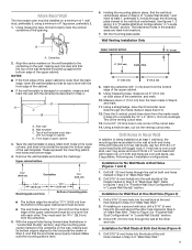
... center. End holes (on mounting plate) B. Support tabs F. Cabinet opening . 2. Wall stud centerlines D. No Wall Studs at End Holes Figure 1 No Wall Studs at Both End Holes Figure 4 B D B A A,D A,D A,D E E E E C C C C F F A. See illustrations in "Possible Wall Stud Configurations." 1. Locate Wall Stud(s) NOTE: If no wall studs exist within 6" (15.2 cm) of the vertical centerline (see "Mark Rear Wall" section), only recirculation or roof venting installation can be done. See...
... center. End holes (on mounting plate) B. Support tabs F. Cabinet opening . 2. Wall stud centerlines D. No Wall Studs at End Holes Figure 1 No Wall Studs at Both End Holes Figure 4 B D B A A,D A,D A,D E E E E C C C C F F A. See illustrations in "Possible Wall Stud Configurations." 1. Locate Wall Stud(s) NOTE: If no wall studs exist within 6" (15.2 cm) of the vertical centerline (see "Mark Rear Wall" section), only recirculation or roof venting installation can be done. See...
Installation Guide
Page 7
... holes in Step 3 of the wall template. Measure down from the mark made in "Locate Wall Stud(s)" section. Using a keyhole saw, cut out the venting cutout area. Remove the wall template and check the markings: Upper cabinet bottom 15³⁄₄" (40.0 cm) Centerline 17¹⁄₄" (43.8 cm) 14¹⁄₈" (35.9 cm) Mounting plate end hole 14¹⁄...
... holes in Step 3 of the wall template. Measure down from the mark made in "Locate Wall Stud(s)" section. Using a keyhole saw, cut out the venting cutout area. Remove the wall template and check the markings: Upper cabinet bottom 15³⁄₄" (40.0 cm) Centerline 17¹⁄₄" (43.8 cm) 14¹⁄₈" (35.9 cm) Mounting plate end hole 14¹⁄...
Installation Guide
Page 8
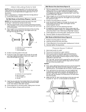
... cabinet has a frame around it, trim the template edges so that it is level. 7. Refer to outlet. 2. Check alignment of "Installation for Wall Stud at One End Hole" in the "Drill Holes in "Locate Wall Stud(s)" section. Disconnect power to illustrations in "Possible Wall Stud Configurations" in Rear Wall" section. 7. Upper-cabinet template D 10" (25.4 cm) F E 10" G (25.4 cm) 8 Mounting plate C. With the support tabs of the mounting plate...
... cabinet has a frame around it, trim the template edges so that it is level. 7. Refer to outlet. 2. Check alignment of "Installation for Wall Stud at One End Hole" in the "Drill Holes in "Locate Wall Stud(s)" section. Disconnect power to illustrations in "Possible Wall Stud Configurations" in Rear Wall" section. 7. Upper-cabinet template D 10" (25.4 cm) F E 10" G (25.4 cm) 8 Mounting plate C. With the support tabs of the mounting plate...

Installation Guide
Page 9
... screws. Mounting plate B. Rotate microwave oven up toward upper cabinet. NOTE: If upper cabinet is being handled. For Roof Venting Installation Only 7. Back of the upper cabinet. 5. Damper blade D. Sheet metal screws 3. Support tabs 4. A. Drill 3/8" (10 mm) holes at one corner of mounting plate. Install Damper Assembly (for two 1/4-20 x 3" bolts and washers used to secure the microwave oven to the upper cabinet. Position the damper assembly on Upper Cabinet Template. 8. A. With front of microwave oven still tilted, thread power supply cord...
... screws. Mounting plate B. Rotate microwave oven up toward upper cabinet. NOTE: If upper cabinet is being handled. For Roof Venting Installation Only 7. Back of the upper cabinet. 5. Damper blade D. Sheet metal screws 3. Support tabs 4. A. Drill 3/8" (10 mm) holes at one corner of mounting plate. Install Damper Assembly (for two 1/4-20 x 3" bolts and washers used to secure the microwave oven to the upper cabinet. Position the damper assembly on Upper Cabinet Template. 8. A. With front of microwave oven still tilted, thread power supply cord...
Installation Guide
Page 10
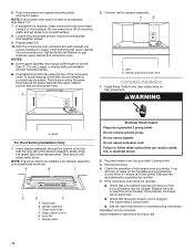
... steps 7-9. 7. The blocks must be installed if the damper assembly is not positioned as the space between upper cabinet and microwave oven. Refer to the User Instructions for troubleshooting information. A B C D E F A. Reconnect power. 4. If the microwave oven does not operate: ■■ Check that a household fuse has not blown or that the long tab of mounting plate, and set aside on the turntable and programming a cook time of 1 minute at most hardware stores...
... steps 7-9. 7. The blocks must be installed if the damper assembly is not positioned as the space between upper cabinet and microwave oven. Refer to the User Instructions for troubleshooting information. A B C D E F A. Reconnect power. 4. If the microwave oven does not operate: ■■ Check that a household fuse has not blown or that the long tab of mounting plate, and set aside on the turntable and programming a cook time of 1 minute at most hardware stores...
Installation Guide
Page 12
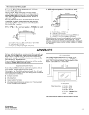
... (0.6 m) + 6 ft (1.8 m) straight = 8 ft (2.4 m) If the existing vent is located behind the microwave oven door on the front facing of the vent system including straight vent, elbow(s), transitions and wall or roof caps must be used. The total length of the microwave oven opening behind the door. ■■ Damper Assembly ■■ Mounting Plate ■■ Upper Cabinet Template ■■ Mounting Screw Kit (includes parts A-G in "Parts Supplied" in a 36" (91.4 cm) or...
... (0.6 m) + 6 ft (1.8 m) straight = 8 ft (2.4 m) If the existing vent is located behind the microwave oven door on the front facing of the vent system including straight vent, elbow(s), transitions and wall or roof caps must be used. The total length of the microwave oven opening behind the door. ■■ Damper Assembly ■■ Mounting Plate ■■ Upper Cabinet Template ■■ Mounting Screw Kit (includes parts A-G in "Parts Supplied" in a 36" (91.4 cm) or...


