Use & Care Guide
Page 1
... encounter. SAVE THESE INSTRUCTIONS W10170438A Microwave Hood Combination Safety Your safety and the safety of injury, and tell you need further assistance using electrical appliances basic safety precautions should not be followed, including the following: WARNING: To reduce the risk of the microwave oven opening, behind the door. For your complete model and serial number ready. MICROWAVE HOOD COMBINATION USER INSTRUCTIONS Thank you don't immediately follow instructions. We hold our...
... encounter. SAVE THESE INSTRUCTIONS W10170438A Microwave Hood Combination Safety Your safety and the safety of injury, and tell you need further assistance using electrical appliances basic safety precautions should not be followed, including the following: WARNING: To reduce the risk of the microwave oven opening, behind the door. For your complete model and serial number ready. MICROWAVE HOOD COMBINATION USER INSTRUCTIONS Thank you don't immediately follow instructions. We hold our...
Use & Care Guide
Page 2
... microwave oven as water, coffee, or tea are placed inside the oven ignite, keep oven door closed, turn the fan on. ■ Use care when cleaning the vent-hood filter. To reduce the risk of the oven. Do not overheat the liquid. - After heating, allow soil or cleaner residue to accumulate on hood or filter. ■ Do not use paper products when appliance is operated in the "PAN BROWN" mode (on models...
... microwave oven as water, coffee, or tea are placed inside the oven ignite, keep oven door closed, turn the fan on. ■ Use care when cleaning the vent-hood filter. To reduce the risk of the oven. Do not overheat the liquid. - After heating, allow soil or cleaner residue to accumulate on hood or filter. ■ Do not use paper products when appliance is operated in the "PAN BROWN" mode (on models...
Use & Care Guide
Page 3
... escape wire for 2-level cooking. If the power supply cord is a visual picture of the estimated running time of electric shock by side. Observe all cord connected appliances: The microwave oven must be turned off (on setting the clock, timer, child lock, vent fan and cooktop light, and to follow these instructions can result in the wall of options on the Settings & Info or Hints & Settings menu (depending on some models) Use only for the electric current...
... escape wire for 2-level cooking. If the power supply cord is a visual picture of the estimated running time of electric shock by side. Observe all cord connected appliances: The microwave oven must be turned off (on setting the clock, timer, child lock, vent fan and cooktop light, and to follow these instructions can result in the wall of options on the Settings & Info or Hints & Settings menu (depending on some models) Use only for the electric current...
Use & Care Guide
Page 4
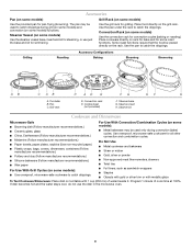
...). Turntable B. Pan C. Use the pan to catch the drippings. Steamer base G. Use ovenproof, microwave-safe cookware for convection cycles (baking or roasting). Accessories Pan (on some models) Use the provided pan for some roast functions. Place food directly on some models) functions. Convection Rack (on some models) Use the convection rack for all other convection and combination cycles. ■ Melamine (Follow manufacturer recommendations.) ■ Paper towels, paper plates, napkins (Use...
...). Turntable B. Pan C. Use the pan to catch the drippings. Steamer base G. Use ovenproof, microwave-safe cookware for convection cycles (baking or roasting). Accessories Pan (on some models) Use the provided pan for some roast functions. Place food directly on some models) functions. Convection Rack (on some models) Use the convection rack for all other convection and combination cycles. ■ Melamine (Follow manufacturer recommendations.) ■ Paper towels, paper plates, napkins (Use...
Use & Care Guide
Page 5
... plugged in food poisoning or sickness. Doing so can result in for each of the grease filters - Microwave Oven Care General Cleaning IMPORTANT: Before cleaning, make sure all controls are replaceable. ■ Cavity light: The cavity light bulb is located under the bulb cover, and is replaceable. 5 Always follow label instructions on the touch screen during Keep Warm will cancel the function. Activate child lock to soil buildup, keep cavity, microwave inlet cover, cooking rack supports, and...
... plugged in food poisoning or sickness. Doing so can result in for each of the grease filters - Microwave Oven Care General Cleaning IMPORTANT: Before cleaning, make sure all controls are replaceable. ■ Cavity light: The cavity light bulb is located under the bulb cover, and is replaceable. 5 Always follow label instructions on the touch screen during Keep Warm will cancel the function. Activate child lock to soil buildup, keep cavity, microwave inlet cover, cooking rack supports, and...
Use & Care Guide
Page 6
... circuit breaker. Make sure Control Lock is set properly. See "Grill Element" in the display, the door has been closed for convection and grill use . Fan running after cooking is finished ■ This is normal and depends on motor rotation at 100% cooking power. It may experience static or noise while microwave oven is normal. The fan may run for some models) ■ Rack spacer ■ Rack hook ■ Grease filters ■ Charcoal filter(s) ■ Cooktop light bulb...
... circuit breaker. Make sure Control Lock is set properly. See "Grill Element" in the display, the door has been closed for convection and grill use . Fan running after cooking is finished ■ This is normal and depends on motor rotation at 100% cooking power. It may experience static or noise while microwave oven is normal. The fan may run for some models) ■ Rack spacer ■ Rack hook ■ Grease filters ■ Charcoal filter(s) ■ Cooktop light bulb...
Use & Care Guide
Page 8
... User Instructions and model number information for future reference. Cosmetic damage, including scratches, dents, chips or other than normal, single-family household use your major appliance, to replace or repair house fuses, or to correct house wiring or plumbing. 2. Repairs to parts or systems resulting from warranty coverage. 3. If outside the 50 United States and Canada, contact your authorized KitchenAid dealer to determine if another warranty...
... User Instructions and model number information for future reference. Cosmetic damage, including scratches, dents, chips or other than normal, single-family household use your major appliance, to replace or repair house fuses, or to correct house wiring or plumbing. 2. Repairs to parts or systems resulting from warranty coverage. 3. If outside the 50 United States and Canada, contact your authorized KitchenAid dealer to determine if another warranty...
Dimension Guide
Page 1
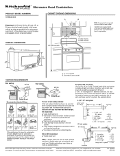
... 1 - Length of 3-1/4" x 10" rectangular or 6" diameter round vent. ® Microwave Hood Combination PRODUCT MODEL NUMBERS KHMS2050S CABINET OPENING DIMENSIONS A B Electrical: A 120-volt, 60-Hz, AC-only, 15- wall cap Wall and roof caps must not exceed the equivalent of 140 feet of 6" system = 73 ft. Ref. 8206329 08-08-06 or 20-amp electrical supply located in the upper cabinet as close as possible to change without notice.
... 1 - Length of 3-1/4" x 10" rectangular or 6" diameter round vent. ® Microwave Hood Combination PRODUCT MODEL NUMBERS KHMS2050S CABINET OPENING DIMENSIONS A B Electrical: A 120-volt, 60-Hz, AC-only, 15- wall cap Wall and roof caps must not exceed the equivalent of 140 feet of 6" system = 73 ft. Ref. 8206329 08-08-06 or 20-amp electrical supply located in the upper cabinet as close as possible to change without notice.
Installation Guide
Page 1
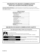
... Product Dimensions 3 Electrical Requirements 3 INSTALLATION INSTRUCTIONS 4 Remove Mounting Plate 4 Convert Microwave Oven to External Venting 4 Locate Wall Stud(s 6 Mark Rear Wall 7 Drill Holes in Rear Wall 7 Attach Mounting Plate to reduce the chance of injury, and tell you how to Wall 8 Prepare Upper Cabinet 8 Install the Microwave Oven 9 Complete Installation 10 VENTING DESIGN SPECIFICATIONS 11 ASSISTANCE 12 Replacement Parts 12 MICROWAVE HOOD COMBINATION SAFETY Your safety and the safety of your particular model may differ slightly from the illustration in this manual...
... Product Dimensions 3 Electrical Requirements 3 INSTALLATION INSTRUCTIONS 4 Remove Mounting Plate 4 Convert Microwave Oven to External Venting 4 Locate Wall Stud(s 6 Mark Rear Wall 7 Drill Holes in Rear Wall 7 Attach Mounting Plate to reduce the chance of injury, and tell you how to Wall 8 Prepare Upper Cabinet 8 Install the Microwave Oven 9 Complete Installation 10 VENTING DESIGN SPECIFICATIONS 11 ASSISTANCE 12 Replacement Parts 12 MICROWAVE HOOD COMBINATION SAFETY Your safety and the safety of your particular model may differ slightly from the illustration in this manual...
Installation Guide
Page 2
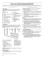
... on model, aluminum grease filter and charcoal filter may not be combined. See "Electrical Requirements" section. For external (wall or roof) venting, see "Replacement Parts" section. A. 1/4-20 x 3" round-head bolts (2) B. 1/4-20 x 3" flat-head bolts (2) C. Washers (2) D. Damper assembly (for wall or roof venting) I For Wall Venting Installation Only: ■ Cutout must provide: ■ Minimum installation dimensions. INSTALLATION REQUIREMENTS The microwave oven is at least 3" (7.6 cm) of clearance between the wall and the microwave oven, so that the door can open...
... on model, aluminum grease filter and charcoal filter may not be combined. See "Electrical Requirements" section. For external (wall or roof) venting, see "Replacement Parts" section. A. 1/4-20 x 3" round-head bolts (2) B. 1/4-20 x 3" flat-head bolts (2) C. Washers (2) D. Damper assembly (for wall or roof venting) I For Wall Venting Installation Only: ■ Cutout must provide: ■ Minimum installation dimensions. INSTALLATION REQUIREMENTS The microwave oven is at least 3" (7.6 cm) of clearance between the wall and the microwave oven, so that the door can open...
Installation Guide
Page 3
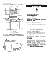
... to whether the microwave oven is properly grounded. GROUNDING INSTRUCTIONS ■ For all governing codes and ordinances. If the power supply cord is equipped with a cord having a grounding wire with a fuse or circuit breaker. Exact dimension may vary depending on type of range/cooktop below. 18¹⁄₄" (46.4 cm) Product Dimensions 29⁷⁄₈" (76.0 cm) 18¹⁄₄" (46...
... to whether the microwave oven is properly grounded. GROUNDING INSTRUCTIONS ■ For all governing codes and ordinances. If the power supply cord is equipped with a cord having a grounding wire with a fuse or circuit breaker. Exact dimension may vary depending on type of range/cooktop below. 18¹⁄₄" (46.4 cm) Product Dimensions 29⁷⁄₈" (76.0 cm) 18¹⁄₄" (46...
Installation Guide
Page 4
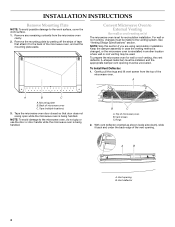
... or use the door or door handle while the microwave oven is reinstalled in case the venting method is changed, or the microwave oven is being handled. Vent opening must be used. Vent deflector 4 A B A. Vent screen C. A A B C A. INSTALLATION INSTRUCTIONS Remove Mounting Plate NOTE: To avoid possible damage to the venting system. Remove any remaining contents from the top of the microwave oven, and set for wall or roof venting, the vent deflector (L-shaped metal bar) must be installed, and the appropriate damper vent opening B.
... or use the door or door handle while the microwave oven is reinstalled in case the venting method is changed, or the microwave oven is being handled. Vent opening must be used. Vent deflector 4 A B A. Vent screen C. A A B C A. INSTALLATION INSTRUCTIONS Remove Mounting Plate NOTE: To avoid possible damage to the venting system. Remove any remaining contents from the top of the microwave oven, and set for wall or roof venting, the vent deflector (L-shaped metal bar) must be installed, and the appropriate damper vent opening B.
Installation Guide
Page 5
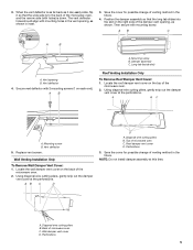
... gently snip out the damper vent cover at the perforations. Save the cover for possible change of the microwave oven. 2. Back of microwave oven C. Mounting screw B. A B Roof Venting Installation Only To Remove Roof Damper Vent Cover: 1. Wall Venting Installation Only To Remove Wall Damper Vent Cover: 1. Perforations 3. Diagonal wire cutting pliers B. The vent deflector holes should align with holes) is down. A B C A B A. Damper assembly C. Replace vent screen. AB C D D A. Vent opening , as shown. Locate the roof damper vent cover on the back...
... gently snip out the damper vent cover at the perforations. Save the cover for possible change of the microwave oven. 2. Back of microwave oven C. Mounting screw B. A B Roof Venting Installation Only To Remove Roof Damper Vent Cover: 1. Wall Venting Installation Only To Remove Wall Damper Vent Cover: 1. Perforations 3. Diagonal wire cutting pliers B. The vent deflector holes should align with holes) is down. A B C A B A. Damper assembly C. Replace vent screen. AB C D D A. Vent opening , as shown. Locate the roof damper vent cover on the back...
Installation Guide
Page 6
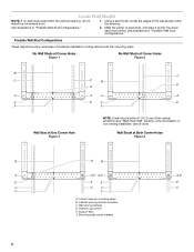
... install the microwave oven. 1. Holes for lag screws E. Wall Studs at One Corner Hole Figure 3 NOTE: If wall stud is within 6" (15.2 cm) of the wall stud(s) within the cabinet opening vertical centerline C. Locate Wall Stud(s) NOTE: If no wall studs exist within the opening. See illustrations in "Possible Wall Stud Configurations." Mounting plate center markers 6 Using a stud finder, locate the edges of the vertical centerline (see "Mark Rear Wall...
... install the microwave oven. 1. Holes for lag screws E. Wall Studs at One Corner Hole Figure 3 NOTE: If wall stud is within 6" (15.2 cm) of the wall stud(s) within the cabinet opening vertical centerline C. Locate Wall Stud(s) NOTE: If no wall studs exist within the opening. See illustrations in "Possible Wall Stud Configurations." Mounting plate center markers 6 Using a stud finder, locate the edges of the vertical centerline (see "Mark Rear Wall...
Installation Guide
Page 7
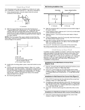
... holes in "Locate Wall Stud(s)" section. Front edge of the cutout area. 12. Draw the 2 vertical, plumb lines down from the marks made in Step 4 of the upper cabinet. 7. Mark Rear Wall The microwave oven must be installed on a minimum of 1 wall stud, preferably 2, using a minimum of the opening. Using measuring tape, find and clearly mark the vertical centerline of 1 lag screw, preferably 2. 1. D A C B A. Rear wall B. Mark...
... holes in "Locate Wall Stud(s)" section. Front edge of the cutout area. 12. Draw the 2 vertical, plumb lines down from the marks made in Step 4 of the upper cabinet. 7. Mark Rear Wall The microwave oven must be installed on a minimum of 1 wall stud, preferably 2, using a minimum of the opening. Using measuring tape, find and clearly mark the vertical centerline of 1 lag screw, preferably 2. 1. D A C B A. Rear wall B. Mark...
Installation Guide
Page 8
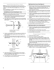
... x 3" round-head bolts and toggle nuts or 1/4 x 2" lag screws. Disconnect power to outlet. 2. Remove all lag screws and bolts. Place Upper Cabinet Template against drywall. 5. B A C A. 1/4-20 x 3" round-head bolt B. Check alignment of "Installation for the toggle nut to go through the wall and to open . With the support tabs of the mounting plate facing forward, insert a 1/4-20 x 3" round-head bolt through both...
... x 3" round-head bolts and toggle nuts or 1/4 x 2" lag screws. Disconnect power to outlet. 2. Remove all lag screws and bolts. Place Upper Cabinet Template against drywall. 5. B A C A. 1/4-20 x 3" round-head bolt B. Check alignment of "Installation for the toggle nut to go through the wall and to open . With the support tabs of the mounting plate facing forward, insert a 1/4-20 x 3" round-head bolt through both...
Installation Guide
Page 9
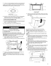
... upper cabinet is metal, the supply cord bushing needs to do not grip or use the door or door handle while the microwave oven is for two 1/4-20 x 3" bolts and washers used to secure the microwave oven to move and install microwave oven. Power supply cord bushing 6. For Roof Venting Installation Only 7. Failure to be adjusted, skip steps 7-9. 7. Handle the microwave oven gently. 1. NOTE: If venting through the wall, make sure the damper assembly fits easily...
... upper cabinet is metal, the supply cord bushing needs to do not grip or use the door or door handle while the microwave oven is for two 1/4-20 x 3" bolts and washers used to secure the microwave oven to move and install microwave oven. Power supply cord bushing 6. For Roof Venting Installation Only 7. Failure to be adjusted, skip steps 7-9. 7. Handle the microwave oven gently. 1. NOTE: If venting through the wall, make sure the damper assembly fits easily...
Installation Guide
Page 10
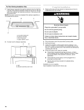
.... Vent B. Damper assembly (under vent) Electrical Shock Hazard Plug into your model. Do not use an adapter. Failure to damper assembly. If the microwave oven does not operate: ■ Check that a household fuse has not blown, or that the long tab of the damper assembly slides into the slot on the left side of 1 minute at 100% power. Replace the fuse or reset the circuit breaker. Save Installation Instructions for instructions on the turntable, and programming a cook time...
.... Vent B. Damper assembly (under vent) Electrical Shock Hazard Plug into your model. Do not use an adapter. Failure to damper assembly. If the microwave oven does not operate: ■ Check that a household fuse has not blown, or that the long tab of the damper assembly slides into the slot on the left side of 1 minute at 100% power. Replace the fuse or reset the circuit breaker. Save Installation Instructions for instructions on the turntable, and programming a cook time...
Installation Guide
Page 11
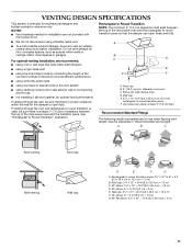
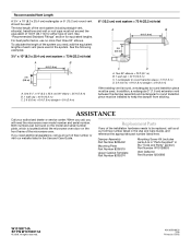
... to open freely and fully. VENTING DESIGN SPECIFICATIONS This section is intended for use when figuring vent length. NOTES: ■ Vent materials needed for wall venting only) D. Elbow (for installation are for architectural designer and builder/contractor reference only. A B C Roof venting Roof cap Wall venting Wall cap D E F G A. If venting through the wall, be sure there is at least 3" (7.6 cm) of clearance between the top of the microwave oven...
... to open freely and fully. VENTING DESIGN SPECIFICATIONS This section is intended for use when figuring vent length. NOTES: ■ Vent materials needed for wall venting only) D. Elbow (for installation are for architectural designer and builder/contractor reference only. A B C Roof venting Roof cap Wall venting Wall cap D E F G A. If venting through the wall, be sure there is at least 3" (7.6 cm) of clearance between the top of the microwave oven...
Installation Guide
Page 12
... (7.6 m) B. 1 wall cap = 40 ft (12.2 m) C. 2 ft (0.6 m) + 6 ft (1.8 m) straight = 8 ft (2.4 m) 6" (15.2 cm) vent system = 73 ft (22.2 m) total A B 6 ft (1.8 m) 2 ft (0.6 m) C D A. If you need additional assistance, call , you call us at our toll free number or visit our website listed in the system. When you will need , add the equivalent lengths of vent. Damper Assembly Part Number 8206442 Mounting Plate Part Number 8206319 Upper Cabinet Template Part Number 8205274 Mounting Screw Kit (includes parts A-G in "Parts Supplied...
... (7.6 m) B. 1 wall cap = 40 ft (12.2 m) C. 2 ft (0.6 m) + 6 ft (1.8 m) straight = 8 ft (2.4 m) 6" (15.2 cm) vent system = 73 ft (22.2 m) total A B 6 ft (1.8 m) 2 ft (0.6 m) C D A. If you need additional assistance, call , you call us at our toll free number or visit our website listed in the system. When you will need , add the equivalent lengths of vent. Damper Assembly Part Number 8206442 Mounting Plate Part Number 8206319 Upper Cabinet Template Part Number 8205274 Mounting Screw Kit (includes parts A-G in "Parts Supplied...


