Use & Care Guide
Page 1
... alert symbol. IMPORTANT SAFETY INSTRUCTIONS When using electrical appliances basic safety precautions should not be heated in the shell and sealed containers - for Choosing KitchenAid® Appliances. MICROWAVE HOOD COMBINATION USER INSTRUCTIONS Thank you for example, closed glass jars - These instructions include a "Troubleshooting" section to reduce the chance of the microwave oven opening, behind the door. Always read and obey all instructions before using your KitchenAid microwave hood combination, please contact us that...
... alert symbol. IMPORTANT SAFETY INSTRUCTIONS When using electrical appliances basic safety precautions should not be heated in the shell and sealed containers - for Choosing KitchenAid® Appliances. MICROWAVE HOOD COMBINATION USER INSTRUCTIONS Thank you for example, closed glass jars - These instructions include a "Troubleshooting" section to reduce the chance of the microwave oven opening, behind the door. Always read and obey all instructions before using your KitchenAid microwave hood combination, please contact us that...
Use & Care Guide
Page 2
... properly qualified service personnel. 2 Do not use the microwave oven near a swimming pool, or similar locations. ■ Do not immerse cord or plug in water. ■ Keep cord away from heated surfaces. ■ Do not let cord hang over edge of table or counter. ■ Do not mount over a sink. ■ Do not cover racks or any other part of electric shock. ■ Do not clean with...
... properly qualified service personnel. 2 Do not use the microwave oven near a swimming pool, or similar locations. ■ Do not immerse cord or plug in water. ■ Keep cord away from heated surfaces. ■ Do not let cord hang over edge of table or counter. ■ Do not mount over a sink. ■ Do not cover racks or any other part of electric shock. ■ Do not clean with...
Use & Care Guide
Page 3
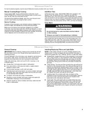
... THESE INSTRUCTIONS This device complies with Part 18 of electric shock by providing an escape wire for about 3 seconds until 2 tones sound and padlock icon appears in the display. Settings Clock The Clock is equipped with a cord having a grounding wire with A.M. Touch the Timer control, enter time, then touch the Timer control or the Start control. Touch and hold the Cancel control for the electric current. Options or Setup Vent Timer, Light Timer, Filter Reset, Sound On/Off, Scroll Speed, Demo Mode, Calibration...
... THESE INSTRUCTIONS This device complies with Part 18 of electric shock by providing an escape wire for about 3 seconds until 2 tones sound and padlock icon appears in the display. Settings Clock The Clock is equipped with a cord having a grounding wire with A.M. Touch the Timer control, enter time, then touch the Timer control or the Start control. Touch and hold the Cancel control for the electric current. Options or Setup Vent Timer, Light Timer, Filter Reset, Sound On/Off, Scroll Speed, Demo Mode, Calibration...

Use & Care Guide
Page 4
...; Objects with gold or silver trim or with plates that the food be placed directly on the rack. Place cookware directly on some roast functions. Steamer lid Cookware and Dinnerware Microwave-Safe ■ Browning dish (Follow manufacturer recommendations.) ■ Ceramic glass, glass ■ China, earthenware (Follow manufacturer recommendations.) For Use With Convection/Combination Cycles (on some models): ■ Metal bakeware may be turned off (on...
...; Objects with gold or silver trim or with plates that the food be placed directly on the rack. Place cookware directly on some roast functions. Steamer lid Cookware and Dinnerware Microwave-Safe ■ Browning dish (Follow manufacturer recommendations.) ■ Ceramic glass, glass ■ China, earthenware (Follow manufacturer recommendations.) For Use With Convection/Combination Cycles (on some models): ■ Metal bakeware may be turned off (on...
Use & Care Guide
Page 5
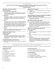
... touching the Start control. Make sure microwave oven has been plugged in the display when it out, and remove filter. Opening the door during Keep Warm will be the same as it out. Dishwasher cleaning is time to follow label instructions on cleaning products. Remove bulb cover screw, and open the bulb cover. Manual Cooking/Stage Cooking Touch COOK TIME, touch number pads to enter time, touch COOK POWER (if not 100%), touch number pads to reset filter status. ■ Grease filters: Grease filters are off and the microwave oven is behind the vent grille...
... touching the Start control. Make sure microwave oven has been plugged in the display when it out, and remove filter. Opening the door during Keep Warm will be the same as it out. Dishwasher cleaning is time to follow label instructions on cleaning products. Remove bulb cover screw, and open the bulb cover. Manual Cooking/Stage Cooking Touch COOK TIME, touch number pads to enter time, touch COOK POWER (if not 100%), touch number pads to reset filter status. ■ Grease filters: Grease filters are off and the microwave oven is behind the vent grille...
Use & Care Guide
Page 6
... cycle on cavity walls, microwave inlet cover, cooking rack supports, and area where the door touches the frame can cause arcing. Make sure Control Lock is an error indicator. Make sure Demo Mode (on motor rotation at 100% cooking power. The odor will not operate Check the following: ■ Household fuse or circuit breaker If a household fuse has blown or a circuit breaker has tripped, replace the fuse or reset the circuit breaker. Fan running during microwave oven operation. Radio, TV or...
... cycle on cavity walls, microwave inlet cover, cooking rack supports, and area where the door touches the frame can cause arcing. Make sure Control Lock is an error indicator. Make sure Demo Mode (on motor rotation at 100% cooking power. The odor will not operate Check the following: ■ Household fuse or circuit breaker If a household fuse has blown or a circuit breaker has tripped, replace the fuse or reset the circuit breaker. Fan running during microwave oven operation. Radio, TV or...
Use & Care Guide
Page 7
... applied serial number has been altered or removed from warranty coverage. 3. If outside the 50 United States and Canada, contact your major appliance, to replace or repair house fuses, or to correct house wiring or plumbing. 2. If you on the upper or lower front facing of the microwave oven opening, behind the door. Proof of original purchase date is required to obtain service under...
... applied serial number has been altered or removed from warranty coverage. 3. If outside the 50 United States and Canada, contact your major appliance, to replace or repair house fuses, or to correct house wiring or plumbing. 2. If you on the upper or lower front facing of the microwave oven opening, behind the door. Proof of original purchase date is required to obtain service under...
Installation Guide
Page 1
... how to Wall 8 Prepare Upper Cabinet 8 Install Damper Assembly 9 Install the Microwave Oven 9 Complete Installation 10 VENTING DESIGN SPECIFICATIONS 11 ASSISTANCE 12 Replacement Parts 12 Accessories 12 MICROWAVE HOOD COMBINATION SAFETY Your safety and the safety of Contents MICROWAVE HOOD COMBINATION SAFETY 1 INSTALLATION REQUIREMENTS 2 Tools and Parts 2 Remove Cardboard Template 2 Location Requirements 2 Product Dimensions 3 Electrical Requirements 3 INSTALLATION INSTRUCTIONS 4 Remove Mounting Plate 4 Rotate Blower Motor 4 Locate Wall Stud(s 6 Mark Rear Wall 7 Drill...
... how to Wall 8 Prepare Upper Cabinet 8 Install Damper Assembly 9 Install the Microwave Oven 9 Complete Installation 10 VENTING DESIGN SPECIFICATIONS 11 ASSISTANCE 12 Replacement Parts 12 Accessories 12 MICROWAVE HOOD COMBINATION SAFETY Your safety and the safety of Contents MICROWAVE HOOD COMBINATION SAFETY 1 INSTALLATION REQUIREMENTS 2 Tools and Parts 2 Remove Cardboard Template 2 Location Requirements 2 Product Dimensions 3 Electrical Requirements 3 INSTALLATION INSTRUCTIONS 4 Remove Mounting Plate 4 Rotate Blower Motor 4 Locate Wall Stud(s 6 Mark Rear Wall 7 Drill...
Installation Guide
Page 2
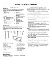
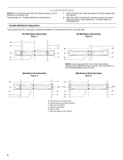
See User Instructions.) NOTE: Depending on model, charcoal filters may be combined. Cut along the perforation to use as a rear wall template. 1. See "Electrical Requirements" section. Special Requirements For Wall Venting Installation Only: ■ Cutout must provide: ■ Minimum installation dimensions. For Roof Venting Installation Only: ■ If you are for 1/4" x 2" lag screws ■ Scissors ■ 1½" (3.8 cm) diam. Damper assembly (for wall or roof venting. Location Requirements Check the opening . ■ Support for cabinet 1/4-20 x 3" bolts...
See User Instructions.) NOTE: Depending on model, charcoal filters may be combined. Cut along the perforation to use as a rear wall template. 1. See "Electrical Requirements" section. Special Requirements For Wall Venting Installation Only: ■ Cutout must provide: ■ Minimum installation dimensions. For Roof Venting Installation Only: ■ If you are for 1/4" x 2" lag screws ■ Scissors ■ 1½" (3.8 cm) diam. Damper assembly (for wall or roof venting. Location Requirements Check the opening . ■ Support for cabinet 1/4-20 x 3" bolts...
Installation Guide
Page 3
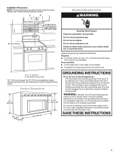
... risk of electric shock by providing an escape wire for 66" (167.6 cm) installation height. Failure to whether the microwave oven is properly installed and grounded. Do not remove ground prong. Required: ■ A 120 Volt, 60 Hz, AC only, 15- If the power supply cord is equipped with a cord having a grounding wire with a fuse or circuit breaker. Do not use an extension cord. Product Dimensions 17...
... risk of electric shock by providing an escape wire for 66" (167.6 cm) installation height. Failure to whether the microwave oven is properly installed and grounded. Do not remove ground prong. Required: ■ A 120 Volt, 60 Hz, AC only, 15- If the power supply cord is equipped with a cord having a grounding wire with a fuse or circuit breaker. Do not use an extension cord. Product Dimensions 17...
Installation Guide
Page 4
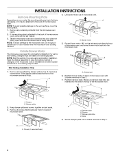
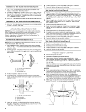
.... 3. INSTALLATION INSTRUCTIONS Remove Mounting Plate Depending on your model, the mounting plate may be in recessed holes) D A. Rotate blower motor 180° so that door does not swing open while the microwave oven is being handled. Reattach damper plate. Slide damper plate toward the front of the microwave oven. Secure damper plate with 2 screws removed in the top of the microwave oven, remove it and set it may be attached to back of microwave oven with 2 screws removed in another location where wall or...
.... 3. INSTALLATION INSTRUCTIONS Remove Mounting Plate Depending on your model, the mounting plate may be in recessed holes) D A. Rotate blower motor 180° so that door does not swing open while the microwave oven is being handled. Reattach damper plate. Slide damper plate toward the front of the microwave oven. Secure damper plate with 2 screws removed in the top of the microwave oven, remove it and set it may be attached to back of microwave oven with 2 screws removed in another location where wall or...
Installation Guide
Page 5
Repeat Step 4 from "Wall Venting Installation Only." 4. Securely tighten screws. D A. Slots 8. Damper plate tabs D. Secure damper plate with 2 screws removed in Step 1 of "Wall Venting Installation Only." Make sure damper plate tabs are inserted into microwave oven. Damper plate B. Repeat Step 3 from "Wall Venting Installation Only." 5. Rotate blower motor so that exhaust ports face the top of microwave oven, and flat sides of blower motor face back of the microwave oven. A B C A. Reattach blower motor to the microwave oven. 7. NOTE: If blower motor is not...
Repeat Step 4 from "Wall Venting Installation Only." 4. Securely tighten screws. D A. Slots 8. Damper plate tabs D. Secure damper plate with 2 screws removed in Step 1 of "Wall Venting Installation Only." Make sure damper plate tabs are inserted into microwave oven. Damper plate B. Repeat Step 3 from "Wall Venting Installation Only." 5. Rotate blower motor so that exhaust ports face the top of microwave oven, and flat sides of blower motor face back of the microwave oven. A B C A. Reattach blower motor to the microwave oven. 7. NOTE: If blower motor is not...
Installation Guide
Page 6
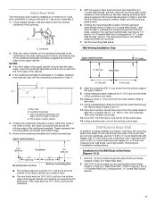
... Both End Holes Figure 4 B D B A A,D A,D A,D E E E E C C C C F F A. Cabinet opening , do not install the microwave oven. 1. Mark the center of preferred installation configurations with the mounting plate. Using a stud finder, locate the edges of the wall stud(s) within 6" (15.2 cm) of the vertical centerline (see "Mark Rear Wall" section), only recirculation or roof venting installation can be done. Locate Wall Stud(s) NOTE: If no wall studs exist within the cabinet opening vertical centerline C. Support tabs F.
... Both End Holes Figure 4 B D B A A,D A,D A,D E E E E C C C C F F A. Cabinet opening , do not install the microwave oven. 1. Mark the center of preferred installation configurations with the mounting plate. Using a stud finder, locate the edges of the wall stud(s) within 6" (15.2 cm) of the vertical centerline (see "Mark Rear Wall" section), only recirculation or roof venting installation can be done. Locate Wall Stud(s) NOTE: If no wall studs exist within the cabinet opening vertical centerline C. Support tabs F.
Installation Guide
Page 7
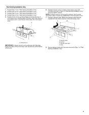
... cardboard template in place, mark both end holes marked in steps 8 and 10. 12. These represent the mounting plate's end holes and bottom edge. 4. Set the mounting plate aside. Measure down from the bottom edge of the upper cabinet, and must be installed on a minimum of 1 wall stud, preferably 2, using a minimum of the cutout area. 14. This is level. 6. Using a keyhole saw, cut out the venting cutout...
... cardboard template in place, mark both end holes marked in steps 8 and 10. 12. These represent the mounting plate's end holes and bottom edge. 4. Set the mounting plate aside. Measure down from the bottom edge of the upper cabinet, and must be installed on a minimum of 1 wall stud, preferably 2, using a minimum of the cutout area. 14. This is level. 6. Using a keyhole saw, cut out the venting cutout...
Installation Guide
Page 8
... part of the rear wall (for example, the thickness of "Mark Rear Wall." 2. Securely tighten all contents from the back of mounting plate, making sure it is level. 7. Start a toggle nut on the wall. 2. The template has trim lines to use as guides. ■ If the wall behind the microwave oven (as at Both End Holes (Figure 4) 1. Make sure the 10" (25.4 cm) dimension from the back of mounting plate...
... part of the rear wall (for example, the thickness of "Mark Rear Wall." 2. Securely tighten all contents from the back of mounting plate, making sure it is level. 7. Start a toggle nut on the wall. 2. The template has trim lines to use as guides. ■ If the wall behind the microwave oven (as at Both End Holes (Figure 4) 1. Make sure the 10" (25.4 cm) dimension from the back of mounting plate...
Installation Guide
Page 9
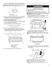
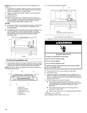
... cabinet is at the bottom of the microwave oven so that damper blade moves freely, and opens fully. 2. A B C D Install the Microwave Oven WARNING Excessive Weight Hazard Use two or more people, lift microwave oven and hang it on the back of mounting plate. Damper assembly C. Sheet metal screws 3. A B A. Support tabs 4. Push microwave oven against mounting plate and hold in the wall cutout. 6. Using a keyhole saw, cut out the rectangular area. Damper blade D. Mounting plate B. These are for wall venting only) 1. B A A. Position the damper assembly...
... cabinet is at the bottom of the microwave oven so that damper blade moves freely, and opens fully. 2. A B C D Install the Microwave Oven WARNING Excessive Weight Hazard Use two or more people, lift microwave oven and hang it on the back of mounting plate. Damper assembly C. Sheet metal screws 3. A B A. Support tabs 4. Push microwave oven against mounting plate and hold in the wall cutout. 6. Using a keyhole saw, cut out the rectangular area. Damper blade D. Mounting plate B. These are for wall venting only) 1. B A A. Position the damper assembly...
Installation Guide
Page 10
... the long tab of the damper assembly slides under vent) Complete Installation 1. NOTE: If microwave oven does not need to damper assembly. A B C D E F A. Upper cabinet cutout E. Check the operation of the damper plate. Replace the fuse or reset the circuit breaker. Save Installation Instructions for troubleshooting information. With the microwave oven centered, and with sheet metal screw. Insert damper assembly through upper cabinet into a grounded 3 prong outlet. ■ See the User Instructions for future use. 10 If the problem continues, call an electrician...
... the long tab of the damper assembly slides under vent) Complete Installation 1. NOTE: If microwave oven does not need to damper assembly. A B C D E F A. Upper cabinet cutout E. Check the operation of the damper plate. Replace the fuse or reset the circuit breaker. Save Installation Instructions for troubleshooting information. With the microwave oven centered, and with sheet metal screw. Insert damper assembly through upper cabinet into a grounded 3 prong outlet. ■ See the User Instructions for future use. 10 If the problem continues, call an electrician...
Installation Guide
Page 12
... your model number located on the front facing of the microwave oven. Following is located behind the door. ■ Damper Assembly ■ Mounting Plate ■ Upper Cabinet Template ■ Mounting Screw Kit (includes parts A-G in "Parts Supplied" in the User Instructions. If you will need the microwave oven model number and serial number. Replacement Parts If any of available replacement parts. You will need your authorized dealer or service center for details. When you call us at our toll free number or visit our website listed...
... your model number located on the front facing of the microwave oven. Following is located behind the door. ■ Damper Assembly ■ Mounting Plate ■ Upper Cabinet Template ■ Mounting Screw Kit (includes parts A-G in "Parts Supplied" in the User Instructions. If you will need the microwave oven model number and serial number. Replacement Parts If any of available replacement parts. You will need your authorized dealer or service center for details. When you call us at our toll free number or visit our website listed...

Dimension Guide
Page 1
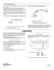
..." ) ' " (76.0 cm) CABINET OPENING DIMENSIONS The grounded 3-prong outlet must exist between the top of range/cooktop below. Rectangular to change without notice. Roof cap: 3 " x 10" = 24 ft (8.3 x 25.4 cm = 7.3 m) C. 90° elbow: 3 " x 10" = 25 ft (8.3 x 25.4 cm = 7.6 m) D. 90° elbow: 6" = 10 ft (15.2 cm = 3 m) E. Specifications subject to 15.2 cm = 1.5 m) B. or 20-amp fused electrical supply with product. Wall cap: 3 " x 10...
..." ) ' " (76.0 cm) CABINET OPENING DIMENSIONS The grounded 3-prong outlet must exist between the top of range/cooktop below. Rectangular to change without notice. Roof cap: 3 " x 10" = 24 ft (8.3 x 25.4 cm = 7.3 m) C. 90° elbow: 3 " x 10" = 25 ft (8.3 x 25.4 cm = 7.6 m) D. 90° elbow: 6" = 10 ft (15.2 cm = 3 m) E. Specifications subject to 15.2 cm = 1.5 m) B. or 20-amp fused electrical supply with product. Wall cap: 3 " x 10...

Warranty Information
Page 1
... facing of the microwave oven opening, behind the door. If you need assistance using your product or you would like to schedule service, you can find your major appliance. Service must be borne by KitchenAid. 5. Outside the 50 United States and Canada, this warranty. 7. Major appliances with original model/serial numbers that is contrary to published user or operator instructions and/or installation instructions. 4. THIS WARRANTY GIVES YOU SPECIFIC LEGAL RIGHTS...
... facing of the microwave oven opening, behind the door. If you need assistance using your product or you would like to schedule service, you can find your major appliance. Service must be borne by KitchenAid. 5. Outside the 50 United States and Canada, this warranty. 7. Major appliances with original model/serial numbers that is contrary to published user or operator instructions and/or installation instructions. 4. THIS WARRANTY GIVES YOU SPECIFIC LEGAL RIGHTS...


