Instruction Manual
Page 2
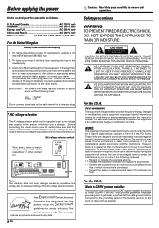
... V only Other countries .......... AC voltage selector switch Move switch lever to match your line voltage. As an ENERGY STAR® Partner, Kenwood Corporation has determined that the setting position of a three-pin plug. * AC voltage selection The AC voltage selector switch on the rear ... "DANGEROUS VOLTAGE" WITHIN THE PRODUCT'S ENCLOSURE THAT MAY BE OF SUFFICIENT MAGNITUDE TO CONSTITUTE A RISK OF ELECTRIC SHOCK TO PERSONS. Reorient or relocate the receiving antenna. - - VIDEO 1 IN VIDEO 1 OUT GND PHONO CD / DVD REC OUT PLAY IN REC OUT PLAY IN PLAY IN DVD MD / TAPE...
... V only Other countries .......... AC voltage selector switch Move switch lever to match your line voltage. As an ENERGY STAR® Partner, Kenwood Corporation has determined that the setting position of a three-pin plug. * AC voltage selection The AC voltage selector switch on the rear ... "DANGEROUS VOLTAGE" WITHIN THE PRODUCT'S ENCLOSURE THAT MAY BE OF SUFFICIENT MAGNITUDE TO CONSTITUTE A RISK OF ELECTRIC SHOCK TO PERSONS. Reorient or relocate the receiving antenna. - - VIDEO 1 IN VIDEO 1 OUT GND PHONO CD / DVD REC OUT PLAY IN REC OUT PLAY IN PLAY IN DVD MD / TAPE...
Instruction Manual
Page 3
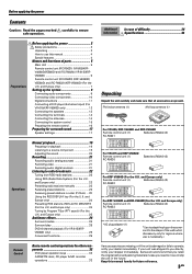
... antenna (1) AM loop antenna (1) For VR-605, KRF-V4060D and KRF-V5560D Remote control unit (1) Batteries (R6/AA) (2) RC-R0621 For VR-...Kenwood recommend that all accessories are missing, or if the unit is damaged or fails to the shape of parts 5 Main Unit 5 Remote control unit (RC-R0621) (VR-605/KRFV4060D/V5560D) and (RC-R0620) (VR...-615/KRFV5060D 6 Remote control unit (RC-R0623) (KRF-V4060D/ V5560D) and (RC-R0622) (KRF-V5060D) (For the U.K. and Europe only 22 Presetting radio stations manually 23 Receiving preset stations 23 Receiving...
... antenna (1) AM loop antenna (1) For VR-605, KRF-V4060D and KRF-V5560D Remote control unit (1) Batteries (R6/AA) (2) RC-R0621 For VR-...Kenwood recommend that all accessories are missing, or if the unit is damaged or fails to the shape of parts 5 Main Unit 5 Remote control unit (RC-R0621) (VR-605/KRFV4060D/V5560D) and (RC-R0620) (VR...-615/KRFV5060D 6 Remote control unit (RC-R0623) (KRF-V4060D/ V5560D) and (RC-R0622) (KRF-V5060D) (For the U.K. and Europe only 22 Presetting radio stations manually 23 Receiving preset stations 23 Receiving...
Instruction Manual
Page 9
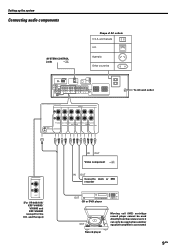
... connected. 9 EN Australia Other countries GND VIDEO DVD IN VIDEO 2 IN FM 75Ω AM ANTENNA MONITOR OUT L DEEMPHASIS CHANNEL SPACE SYSTEM CONTROL 50µs AM 9kHz FM 50kHz 75µs AM 10kHz...DVD player OUT Record player Moving coil (MC) cartridge record player cannot be used directly from the receiver unit. VIDEO 1 IN VIDEO 1 OUT GND PHONO CD / DVD REC OUT PLAY IN REC OUT... PHONO CD/DVD REC OUT PLAY IN REC OUT PLAY IN MD / TAPE VIDEO1 L R AUX [For VR-605/615/ KRF-V4060D/ V5560D and KRF-V5060D (except for the U.K. Setting up the system Connecting audio components SYSTEM...
... connected. 9 EN Australia Other countries GND VIDEO DVD IN VIDEO 2 IN FM 75Ω AM ANTENNA MONITOR OUT L DEEMPHASIS CHANNEL SPACE SYSTEM CONTROL 50µs AM 9kHz FM 50kHz 75µs AM 10kHz...DVD player OUT Record player Moving coil (MC) cartridge record player cannot be used directly from the receiver unit. VIDEO 1 IN VIDEO 1 OUT GND PHONO CD / DVD REC OUT PLAY IN REC OUT... PHONO CD/DVD REC OUT PLAY IN REC OUT PLAY IN MD / TAPE VIDEO1 L R AUX [For VR-605/615/ KRF-V4060D/ V5560D and KRF-V5060D (except for the U.K. Setting up the system Connecting audio components SYSTEM...
Instruction Manual
Page 10
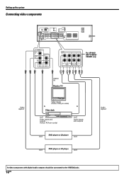
... MAX. VOLTAGE SELECTOR VIDEO DVD IN VIDEO 2 IN MONITOR OUT VIDEO 1 IN VIDEO 1 OUT AUDIO REC OUT PLAY IN PLAY IN DVD VIDEO1 VIDEO 2 For VR-605/ KRF-V4060D/ V5560D only VIDEO IN Monitor TV Video IN/OUT Video inputs (Yellow RCA pin cords) IN IN Video deck OUT Video inputs and... be connected to the VIDEO2 jacks. 10 EN Setting up the system Connecting video components GND VIDEO DVD IN VIDEO 2 IN FM 75Ω AM ANTENNA MONITOR OUT L DEEMPHASIS CHANNEL SPACE SYSTEM CONTROL 50µs AM 9kHz FM 50kHz 75µs AM 10kHz FM 100kHz AUDIO DVD CD / DVD OPTICAL VIDEO...
... MAX. VOLTAGE SELECTOR VIDEO DVD IN VIDEO 2 IN MONITOR OUT VIDEO 1 IN VIDEO 1 OUT AUDIO REC OUT PLAY IN PLAY IN DVD VIDEO1 VIDEO 2 For VR-605/ KRF-V4060D/ V5560D only VIDEO IN Monitor TV Video IN/OUT Video inputs (Yellow RCA pin cords) IN IN Video deck OUT Video inputs and... be connected to the VIDEO2 jacks. 10 EN Setting up the system Connecting video components GND VIDEO DVD IN VIDEO 2 IN FM 75Ω AM ANTENNA MONITOR OUT L DEEMPHASIS CHANNEL SPACE SYSTEM CONTROL 50µs AM 9kHz FM 50kHz 75µs AM 10kHz FM 100kHz AUDIO DVD CD / DVD OPTICAL VIDEO...
Instruction Manual
Page 11
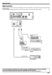
If you have connected any digital components to the receiver, be sure to the VIDEO 2 jacks. (See "Connecting video components".) 11 EN Next, connect the DIGITAL OUT jacks of the demodulator to the KENWOOD RF digital demodulator (DEM-9991D). Connect the video signal and analog audio ...signals to read the "Input mode settings" section carefully. 8 GND VIDEO DVD IN VIDEO 2 IN FM 75Ω AM ANTENNA MONITOR OUT L DEEMPHASIS CHANNEL SPACE SYSTEM...
If you have connected any digital components to the receiver, be sure to the VIDEO 2 jacks. (See "Connecting video components".) 11 EN Next, connect the DIGITAL OUT jacks of the demodulator to the KENWOOD RF digital demodulator (DEM-9991D). Connect the video signal and analog audio ...signals to read the "Input mode settings" section carefully. 8 GND VIDEO DVD IN VIDEO 2 IN FM 75Ω AM ANTENNA MONITOR OUT L DEEMPHASIS CHANNEL SPACE SYSTEM...
Instruction Manual
Page 12
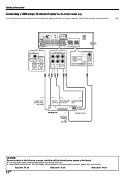
... Back panel : 10 cm 12 EN Setting up the system Connecting a DVD player (6-channel input) (For VR-615/KRF-V5060D only) If you have connected a DVD player to read the "Input mode settings" section... carefully. 8 GND VIDEO DVD IN VIDEO 2 IN FM 75Ω AM ANTENNA MONITOR OUT L DEEMPHASIS CHANNEL SPACE SYSTEM CONTROL 50µs AM 9kHz FM 50kHz 75µs AM 10kHz ...OUT CAUTION Be sure to adhere to the following, or proper ventilation will be sure to the receiver with digital connection, be blocked causing damage or fire hazard. • Do not place any...
... Back panel : 10 cm 12 EN Setting up the system Connecting a DVD player (6-channel input) (For VR-615/KRF-V5060D only) If you have connected a DVD player to read the "Input mode settings" section... carefully. 8 GND VIDEO DVD IN VIDEO 2 IN FM 75Ω AM ANTENNA MONITOR OUT L DEEMPHASIS CHANNEL SPACE SYSTEM CONTROL 50µs AM 9kHz FM 50kHz 75µs AM 10kHz ...OUT CAUTION Be sure to adhere to the following, or proper ventilation will be sure to the receiver with digital connection, be blocked causing damage or fire hazard. • Do not place any...
Instruction Manual
Page 13
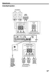
VOLTAGE SELECTOR SUB WOOFER PRE OUT VR-615/KRF-V5560D SURROUND SUB WOOFER SPEAKERS SPEAKER (8-16Ω) (8-16Ω) R GRAY + - L BLUE SW PURPLE Powered sub woofer (For VR-605/ KRF-V5060D/ V4060D) Right Left Surround Speakers (Be sure to connect both surround speakers) Sub woofer 13 EN R L... C RED WHITE GREEN SURROUND SPEAKERS (8-16Ω) + - R GRAY L BLUE VR-605/KRF-V5060D/KRF-V4060D GND VIDEO DVD IN VIDEO 2 IN FM 75Ω AM ANTENNA MONITOR OUT L DEEMPHASIS CHANNEL SPACE SYSTEM CONTROL 50µs AM 9kHz FM 50kHz 75µs AM 10kHz ...
VOLTAGE SELECTOR SUB WOOFER PRE OUT VR-615/KRF-V5560D SURROUND SUB WOOFER SPEAKERS SPEAKER (8-16Ω) (8-16Ω) R GRAY + - L BLUE SW PURPLE Powered sub woofer (For VR-605/ KRF-V5060D/ V4060D) Right Left Surround Speakers (Be sure to connect both surround speakers) Sub woofer 13 EN R L... C RED WHITE GREEN SURROUND SPEAKERS (8-16Ω) + - R GRAY L BLUE VR-605/KRF-V5060D/KRF-V4060D GND VIDEO DVD IN VIDEO 2 IN FM 75Ω AM ANTENNA MONITOR OUT L DEEMPHASIS CHANNEL SPACE SYSTEM CONTROL 50µs AM 9kHz FM 50kHz 75µs AM 10kHz ...
Instruction Manual
Page 14
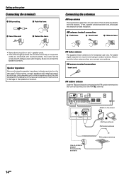
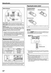
...with reversed polarity, the sound will be unnatural with matching impedance ratings. Connecting the antennas AM loop antenna The supplied loop antenna is for use only. Place it to the speakers or receiver. AM antenna terminal connections 1 Push lever. 2 Insert cord. 3 Release lever. • ... Speaker impedance After confirming the speaker impedance indications printed on the rear panel of the receiver, connect speakers with ambiguous acoustic imaging. FM indoor antenna The supplied indoor antenna is for temporary use indoors. VIDEO 1 IN VIDEO 1 OUT GND PHONO CD ...
...with reversed polarity, the sound will be unnatural with matching impedance ratings. Connecting the antennas AM loop antenna The supplied loop antenna is for use only. Place it to the speakers or receiver. AM antenna terminal connections 1 Push lever. 2 Insert cord. 3 Release lever. • ... Speaker impedance After confirming the speaker impedance indications printed on the rear panel of the receiver, connect speakers with ambiguous acoustic imaging. FM indoor antenna The supplied indoor antenna is for temporary use indoors. VIDEO 1 IN VIDEO 1 OUT GND PHONO CD ...
Instruction Manual
Page 16
... DEEMPHASIS CHANNEL SPACE 50µs AM 9kHz FM 50kHz 75µs AM 10kHz FM 100kHz GND DEEMPHASIS CHANNEL SPACE SYSTEM CONTROL FM 75Ω AM ANTENNA 50µs AM 9kHz FM 50kHz 75µs AM 10kHz FM 100kHz VIDEO DVD AUDIO D IN MONITOR VIDEO 2 OUT L IN R VIDEO 1 IN VIDEO 1 OUT PHONO...
... DEEMPHASIS CHANNEL SPACE 50µs AM 9kHz FM 50kHz 75µs AM 10kHz FM 100kHz GND DEEMPHASIS CHANNEL SPACE SYSTEM CONTROL FM 75Ω AM ANTENNA 50µs AM 9kHz FM 50kHz 75µs AM 10kHz FM 100kHz VIDEO DVD AUDIO D IN MONITOR VIDEO 2 OUT L IN R VIDEO 1 IN VIDEO 1 OUT PHONO...

Instruction Manual
Page 33
... not PHONO input selector is ON. • The SPEAKERS switches are set . • Install the outdoor antenna away from the road. • Turn off the power to the appliance. • Install the receiver farther away from • The input mode is cut off , eliminate the short-circuiting, then turn the..., execute the following procedure to reset the microcomputer and return the unit to its normal operating condition. • Please note that cannot be received. • No antenna is connected. • The broadcast band is not set to the state it left the factory For the U.S.A.
... not PHONO input selector is ON. • The SPEAKERS switches are set . • Install the outdoor antenna away from the road. • Turn off the power to the appliance. • Install the receiver farther away from • The input mode is cut off , eliminate the short-circuiting, then turn the..., execute the following procedure to reset the microcomputer and return the unit to its normal operating condition. • Please note that cannot be received. • No antenna is connected. • The broadcast band is not set to the state it left the factory For the U.S.A.