
Installation Manual
Page 4
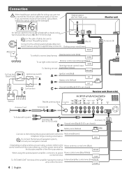
... VIDEO L AV OUTPUT R L R-CAM V-IN CENTER SUB R R VIDEO [MONO] PRE OUTPUT REAR L FRONT L R R POWER Antenna Cord Accessory 5 To Subwoofer system Accessory % (KVT-817DVD only) C Accessory 1 Ground wire (Black) - (To car chassis) Battery wire (Yellow) B (10A) Connect to the terminal that is fixed with a chassis using...wire (Pink/Black) amp control function. ANT CONT When using harness band (Accessory ^). (KVT-817DVD only) For the sake of the film-type antenna. MUTE To connect the Kenwood navigation system, consult your navigation manual. terminal of 30 mm. P.
... VIDEO L AV OUTPUT R L R-CAM V-IN CENTER SUB R R VIDEO [MONO] PRE OUTPUT REAR L FRONT L R R POWER Antenna Cord Accessory 5 To Subwoofer system Accessory % (KVT-817DVD only) C Accessory 1 Ground wire (Black) - (To car chassis) Battery wire (Yellow) B (10A) Connect to the terminal that is fixed with a chassis using...wire (Pink/Black) amp control function. ANT CONT When using harness band (Accessory ^). (KVT-817DVD only) For the sake of the film-type antenna. MUTE To connect the Kenwood navigation system, consult your navigation manual. terminal of 30 mm. P.
Installation Manual
Page 5
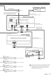
Always connect those wires to the car chassis (ground), you may start a fire. Accessory 3 (KVT-817DVD only) An Optical cable (Accessory 3) is fixed with a chassis using harness band (Accessory ^). (KVT-817DVD only) (Green) Disc Changer etc. (Optional) Connection cable (Included in the disc changer) ...Receiver unit (rear side) TO NAVIGATION I/F TO TV TUNER I/F OPTICAL IN TO MONITOR I/F TO 5L I/F Accessory 2 Optical input (KVT-817DVD only) Connection cable (Included in the Navigation system) TV tuner (Optional) TV ANTENNA INPUT Connection cable (Included in turn may...
Always connect those wires to the car chassis (ground), you may start a fire. Accessory 3 (KVT-817DVD only) An Optical cable (Accessory 3) is fixed with a chassis using harness band (Accessory ^). (KVT-817DVD only) (Green) Disc Changer etc. (Optional) Connection cable (Included in the disc changer) ...Receiver unit (rear side) TO NAVIGATION I/F TO TV TUNER I/F OPTICAL IN TO MONITOR I/F TO 5L I/F Accessory 2 Optical input (KVT-817DVD only) Connection cable (Included in the Navigation system) TV tuner (Optional) TV ANTENNA INPUT Connection cable (Included in turn may...
Installation Manual
Page 6
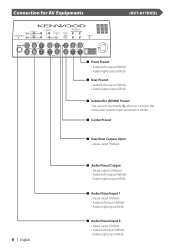
... CENTER SUB [MONO] PRE OUTPUT REAR FRONT L L R R POWER (KVT-817DVD) 6 | English ■ Front Preout • Audio left output (White) • Audio right output (Red) ■ Rear Preout • Audio left output (White) • Audio right output (Red) ■ Subwoofer (MONO) Preout You can use Accessory % when to connect the subwoofer system input terminals...
... CENTER SUB [MONO] PRE OUTPUT REAR FRONT L L R R POWER (KVT-817DVD) 6 | English ■ Front Preout • Audio left output (White) • Audio right output (Red) ■ Rear Preout • Audio left output (White) • Audio right output (Red) ■ Subwoofer (MONO) Preout You can use Accessory % when to connect the subwoofer system input terminals...
Installation Manual
Page 8
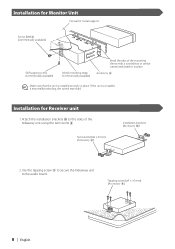
...the hideaway unit using the sems bolts 8. Tapping screw (ø4 × 16 mm) (Accessory 9) 8 | English If the unit is installed securely in place. Sems bolts (M4 × 8 mm) (Accessory 8) Installation brackets (Accessory 0) 2.Use the tapping screw 9 to secure the hideaway unit to the sides of the ...mounting sleeve with a screwdriver or similar utensil and attach it may malfunction (eg, the sound may skip). Accessory 6 Make sure that the unit is unstable, it in place. Installation for Receiver unit 1.Attach the installation brackets 0 to the audio board...
...the hideaway unit using the sems bolts 8. Tapping screw (ø4 × 16 mm) (Accessory 9) 8 | English If the unit is installed securely in place. Sems bolts (M4 × 8 mm) (Accessory 8) Installation brackets (Accessory 0) 2.Use the tapping screw 9 to secure the hideaway unit to the sides of the ...mounting sleeve with a screwdriver or similar utensil and attach it may malfunction (eg, the sound may skip). Accessory 6 Make sure that the unit is unstable, it in place. Installation for Receiver unit 1.Attach the installation brackets 0 to the audio board...
Installation Manual
Page 9
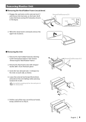
... locks on each side, as shown in the section . 2. Remove the hard rubber frame by referring to the removal procedure in the figure. Removal Tool (Accessory 7 ) English | 9 Remove the Hex-head screw with your hands, being careful not to avoid injury from the catch pins on the back panel. 3. Pull the... washer (M4 × 8) on the removal tool. 5. Removing Monitor Unit ■ Removing the Hard Rubber Frame (escutcheon) 1. Lower the frame and pull it . Removal Tool (Accessory 7 ) Catch Lock 2. Insert the two removal tools 7 deeply into the slots on the lower level.
... locks on each side, as shown in the section . 2. Remove the hard rubber frame by referring to the removal procedure in the figure. Removal Tool (Accessory 7 ) English | 9 Remove the Hex-head screw with your hands, being careful not to avoid injury from the catch pins on the back panel. 3. Pull the... washer (M4 × 8) on the removal tool. 5. Removing Monitor Unit ■ Removing the Hard Rubber Frame (escutcheon) 1. Lower the frame and pull it . Removal Tool (Accessory 7 ) Catch Lock 2. Insert the two removal tools 7 deeply into the slots on the lower level.
Installation Manual
Page 10
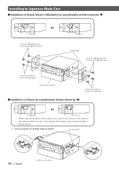
...Brackets at Holes shown by "●" or When using accessories ! If so, tighten the bracket using the bracket shown above, you cannot use screws at both sides as shown below. 1. as shown. Use accessories ! Installing in Japanese-Made Cars ■ Installation on... Toyota, Nissan or Mitsubishi Car using Brackets at Holes shown by "●" or Accessory @ (M5x6mm) or Accessory # (M5x7mm) Car Bracket Accessory @ (M5x6mm) or Accessory # (M5x7mm) Screws (included in audio ...
...Brackets at Holes shown by "●" or When using accessories ! If so, tighten the bracket using the bracket shown above, you cannot use screws at both sides as shown below. 1. as shown. Use accessories ! Installing in Japanese-Made Cars ■ Installation on... Toyota, Nissan or Mitsubishi Car using Brackets at Holes shown by "●" or Accessory @ (M5x6mm) or Accessory # (M5x7mm) Car Bracket Accessory @ (M5x6mm) or Accessory # (M5x7mm) Screws (included in audio ...
Installation Manual
Page 11
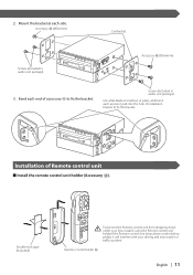
....If the Remote control unit drops down under driving pedals, it will interfere with your driving and may result in audio unit package) Accessory @ (M5x6mm) 3. to fix the bracket. Accessory @ (M5x6mm) Car Bracket Screws (included in a traffic accident. Bend each end of installation bracket to fix the bracket. 2. Screws (included in ...audio unit package) Use a flat-blade screwdriver or pliers, and bend each side. Installation of Remote control unit ■ Install the remote control unit holder (Accessory $). Remote control holder $ English | 11 Mount the bracket at each...
....If the Remote control unit drops down under driving pedals, it will interfere with your driving and may result in audio unit package) Accessory @ (M5x6mm) 3. to fix the bracket. Accessory @ (M5x6mm) Car Bracket Screws (included in a traffic accident. Bend each end of installation bracket to fix the bracket. 2. Screws (included in ...audio unit package) Use a flat-blade screwdriver or pliers, and bend each side. Installation of Remote control unit ■ Install the remote control unit holder (Accessory $). Remote control holder $ English | 11 Mount the bracket at each...