Installation Manual
Page 2
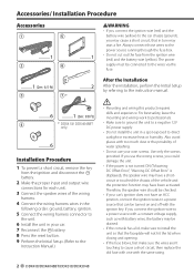
...position, connect the ignition wires to a power source that can be turned on and off with the same rating. 2 DDX418/DDX4048BT/DDX318/DDX3048 The power supply must be drained. • If the console has a lid, make sure to install the unit so that...wires in the following order: ground, battery, ignition. 5 Connect the wiring harness connector to the unit. 6 Install the unit in your own screws. Accessories/ Installation Procedure Accessories 1 5 ..........1 2 6 ..........1 2WARNING • If you connect the ignition wire (red) and the battery wire (yellow) to the car chassis (ground...
...position, connect the ignition wires to a power source that can be turned on and off with the same rating. 2 DDX418/DDX4048BT/DDX318/DDX3048 The power supply must be drained. • If the console has a lid, make sure to install the unit so that...wires in the following order: ground, battery, ignition. 5 Connect the wiring harness connector to the unit. 6 Install the unit in your own screws. Accessories/ Installation Procedure Accessories 1 5 ..........1 2 6 ..........1 2WARNING • If you connect the ignition wire (red) and the battery wire (yellow) to the car chassis (ground...
Installation Manual
Page 4
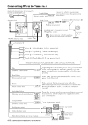
...Accessory 1 FUSE ( 10A ) For best safety, be sure to connect the parking sensor. ⁄ Connect to the vehicle's parking brake detection switch harness. Orange/White (Dimmer control wire) To car light control switch Red (Ignition wire) ACC Ignition key switch Yellow (Battery wire) Black (Ground wire) - (To car chassis) 4 DDX418/DDX4048BT/DDX318...) If no connections are using, connect either the telephone rings or during conversation. (To connect the Kenwood navigation system, consult your navigation manual.) To use the steering wheel remote control feature, you are made...
...Accessory 1 FUSE ( 10A ) For best safety, be sure to connect the parking sensor. ⁄ Connect to the vehicle's parking brake detection switch harness. Orange/White (Dimmer control wire) To car light control switch Red (Ignition wire) ACC Ignition key switch Yellow (Battery wire) Black (Ground wire) - (To car chassis) 4 DDX418/DDX4048BT/DDX318...) If no connections are using, connect either the telephone rings or during conversation. (To connect the Kenwood navigation system, consult your navigation manual.) To use the steering wheel remote control feature, you are made...
Installation Manual
Page 5
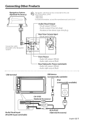
... (White) • Audio right output (Red) USB device (commercially available) iPod (commercially available) CA-U1EX (Optional Accessory) Audio Visual input (iPod/AV Input switchable) KCA-iP22F (Optional Accessory) English 5 Connecting Other Products Navigation System (Optional Accessory) ⁄ Navigation units that can be connected to this unit. (As of December, 2010): • KNA-G610...
... (White) • Audio right output (Red) USB device (commercially available) iPod (commercially available) CA-U1EX (Optional Accessory) Audio Visual input (iPod/AV Input switchable) KCA-iP22F (Optional Accessory) English 5 Connecting Other Products Navigation System (Optional Accessory) ⁄ Navigation units that can be connected to this unit. (As of December, 2010): • KNA-G610...
Installation Manual
Page 6
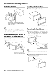
... the upper two locations. 6 DDX418/DDX4048BT/DDX318/DDX3048 Installation on Toyota, Nissan or Mitsubishi Car using Brackets Accessory 3 (M5x6mm) or Accessory 4 (M5x7mm) Car Bracket Accessory 5 Removing the Escutcheon 1 Engage the catch pins on the removal tool 6 and remove the two locks on the lower level. Accessory 6 Catch Lock Accessory 3 (M5x6mm) or Accessory 4 (M5x7mm) ⁄ • The .... Lower the frame and pull it may malfunction (eg, the sound may skip). Installation/Removing the Unit Installing the Unit Installing the Escutcheon 1 Attach accessory 5 to the unit.
... the upper two locations. 6 DDX418/DDX4048BT/DDX318/DDX3048 Installation on Toyota, Nissan or Mitsubishi Car using Brackets Accessory 3 (M5x6mm) or Accessory 4 (M5x7mm) Car Bracket Accessory 5 Removing the Escutcheon 1 Engage the catch pins on the removal tool 6 and remove the two locks on the lower level. Accessory 6 Catch Lock Accessory 3 (M5x6mm) or Accessory 4 (M5x7mm) ⁄ • The .... Lower the frame and pull it may malfunction (eg, the sound may skip). Installation/Removing the Unit Installing the Unit Installing the Escutcheon 1 Attach accessory 5 to the unit.
Installation Manual
Page 7
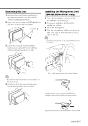
...-face adhesive tape to fix on the removal tool. 4 Pull the unit all the way out with a commercial item of the microphone to the driver. Accessory 6 3 Lower the removal tool toward the bottom, and pull out the unit halfway while pressing towards the inside. Adjust the direction of tape.... Accessory 7 ⁄ • Be careful to avoid injury from the catch pins on the place shown above. Fix a cable with your hands, being careful not to ...
...-face adhesive tape to fix on the removal tool. 4 Pull the unit all the way out with a commercial item of the microphone to the driver. Accessory 6 3 Lower the removal tool toward the bottom, and pull out the unit halfway while pressing towards the inside. Adjust the direction of tape.... Accessory 7 ⁄ • Be careful to avoid injury from the catch pins on the place shown above. Fix a cable with your hands, being careful not to ...


