
Instruction Manual
Page 1
... several operation modes. About the supplied remote control Compared to control other audio/video components. AUDIO VIDEO SURROUND RECEIVER VR-6070 KRF-X9060D INSTRUCTION MANUAL KENWOOD CORPORATION This instruction manual is important to read the operating instructions and obtain a proper understanding of the remote control and how to switch its design ...
... several operation modes. About the supplied remote control Compared to control other audio/video components. AUDIO VIDEO SURROUND RECEIVER VR-6070 KRF-X9060D INSTRUCTION MANUAL KENWOOD CORPORATION This instruction manual is important to read the operating instructions and obtain a proper understanding of the remote control and how to switch its design ...

Instruction Manual
Page 3
only 30 Presetting radio stations manually 30 Receiving preset stations 31 Receiving preset stations in the future. only 32 ...Safety precautions 2 Unpacking 3 How to the AV AUX jacks 20 Connecting the antennas 20 Connecting the system control 21 Preparing the remote control 22 RF remote control function (For VR-6070 only) .... 22 Preparing for surround sound...plug adaptor (1) *Use to adapt the plug on the power cord to operate, notify your shipper immediately. Kenwood recommends that all accessories are missing, or if the unit is damaged or fails to the shape of difficulty...
only 30 Presetting radio stations manually 30 Receiving preset stations 31 Receiving preset stations in the future. only 32 ...Safety precautions 2 Unpacking 3 How to the AV AUX jacks 20 Connecting the antennas 20 Connecting the system control 21 Preparing the remote control 22 RF remote control function (For VR-6070 only) .... 22 Preparing for surround sound...plug adaptor (1) *Use to adapt the plug on the power cord to operate, notify your shipper immediately. Kenwood recommends that all accessories are missing, or if the unit is damaged or fails to the shape of difficulty...

Instruction Manual
Page 4
...additional information such as a detailed explanation of difficulty" (troubleshooting) and "Specifications". KENWOOD U.S.A. Before applying the power How to which can save energy. Preparations Shows you how to operate other AV components (TV, VCR, DVD player, CD player, etc.) using the remote ... harmful interference to radio or television reception, which the receiver is divided into an outlet on the receiver. FCC WARNING This equipment may deform the plastic component. FCC Compliance Notice Audio-video Receiver, VR-6070 These devices comply with a soft, dry cloth. Since...
...additional information such as a detailed explanation of difficulty" (troubleshooting) and "Specifications". KENWOOD U.S.A. Before applying the power How to which can save energy. Preparations Shows you how to operate other AV components (TV, VCR, DVD player, CD player, etc.) using the remote ... harmful interference to radio or television reception, which the receiver is divided into an outlet on the receiver. FCC WARNING This equipment may deform the plastic component. FCC Compliance Notice Audio-video Receiver, VR-6070 These devices comply with a soft, dry cloth. Since...

Instruction Manual
Page 5
...PRO LOGIC, provides greater advantages in the original recording. DVD 6-channel input If you own a DVD player equipped with this receiver allows you to obtain the full surround sound impact of DVD source material featuring multi-channel encoding. Universal IR (InfraRed) remote... produces an impressive surround sound from video software marked and three-dimensional space from the 5.1 channel sources. RF remote signal (For VR-6070 only) You can listen to audio CDs, MDs, Broadcast and Home Theater using a matrix decoder that provides several convenient tuning functions...
...PRO LOGIC, provides greater advantages in the original recording. DVD 6-channel input If you own a DVD player equipped with this receiver allows you to obtain the full surround sound impact of DVD source material featuring multi-channel encoding. Universal IR (InfraRed) remote... produces an impressive surround sound from video software marked and three-dimensional space from the 5.1 channel sources. RF remote signal (For VR-6070 only) You can listen to audio CDs, MDs, Broadcast and Home Theater using a matrix decoder that provides several convenient tuning functions...

Instruction Manual
Page 6
... EQ key ¶ Use to select SPEAKER EQ's setting. 6 Surround indicators THX indicator ‡ Lights when the receiver is in the THX mode. STANDBY indicator 2 POWER ON/STANDBY key (For VR-6070) £ Use to turn the power ON/STANDBY when the POWER is turned ON. SPEAKER EQ indicator • ...6CH CD/DVD PHONO TUNER VIDEO 1 VIDEO 2 VIDEO 3 MD/TAPE SOUND TONE SETUP BAND AUTO MEMORY VOLUME CONTROL MULTI CONTROL LISTEN MODE DOWN UP MUTE AV AUX S VIDEO VIDEO L-AUDIO-R 1 POWER ON/OFF key (For KRF-X9060D) £ Use to turn the main power ON/OFF. 2 ON/...
... EQ key ¶ Use to select SPEAKER EQ's setting. 6 Surround indicators THX indicator ‡ Lights when the receiver is in the THX mode. STANDBY indicator 2 POWER ON/STANDBY key (For VR-6070) £ Use to turn the power ON/STANDBY when the POWER is turned ON. SPEAKER EQ indicator • ...6CH CD/DVD PHONO TUNER VIDEO 1 VIDEO 2 VIDEO 3 MD/TAPE SOUND TONE SETUP BAND AUTO MEMORY VOLUME CONTROL MULTI CONTROL LISTEN MODE DOWN UP MUTE AV AUX S VIDEO VIDEO L-AUDIO-R 1 POWER ON/OFF key (For KRF-X9060D) £ Use to turn the main power ON/OFF. 2 ON/...

Instruction Manual
Page 7
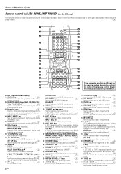
... ª RETURN key Use to control a variety of parts Remote control unit (RC-R0813) (VR-6070) and (RC-R0814) (KRF-X9060D) This remote control unit can be use not only for Kenwood products but also for other components. Names and functions of settings. INPUT SEL TOP MENU MENU SET ...DVD PHONO TUNER VIDEO 1 VIDEO 2 VIDEO 3 MD/TAPE INPUT SELECTOR AV AUX LOUDNESS TONE BASS BOOST * ( ) ¡ § ¶ • ª º ⁄ ¤ ‹ If the name of a function is different on › the receiver and on the remote control, fi the name of the original remote...
... ª RETURN key Use to control a variety of parts Remote control unit (RC-R0813) (VR-6070) and (RC-R0814) (KRF-X9060D) This remote control unit can be use not only for Kenwood products but also for other components. Names and functions of settings. INPUT SEL TOP MENU MENU SET ...DVD PHONO TUNER VIDEO 1 VIDEO 2 VIDEO 3 MD/TAPE INPUT SELECTOR AV AUX LOUDNESS TONE BASS BOOST * ( ) ¡ § ¶ • ª º ⁄ ¤ ‹ If the name of a function is different on › the receiver and on the remote control, fi the name of the original remote...
Instruction Manual
Page 8
... /pause key. only) This remote control unit can be used not only for Kenwood products but also for selection adjustments during SOUND, SET UP and PRESET channel functions.... INPUT SELECTOR keys (DVD/6CH, CD/DVD, PHONO, TUNER, VIDEO 1, VIDEO 2, VIDEO 3, MD/TAPE, AV AUX) § Use to select the input sources. & LOUDNESS key ¶ Use to switch the status... + - r 1 2 3 4 5 6 7 8 9 0 SOURCE POWER LEARN DVD CD CBL/SAT REMOTE MODE VCR TV OTHERS RECEIVER THX 1 2 3 LISTEN MODE 4 5 6 ACTIVE EQ 7 8 9 SPEAKER EQ +10 0 +100 INPUT MODE STEREO DSP MODE MUTE...
... /pause key. only) This remote control unit can be used not only for Kenwood products but also for selection adjustments during SOUND, SET UP and PRESET channel functions.... INPUT SELECTOR keys (DVD/6CH, CD/DVD, PHONO, TUNER, VIDEO 1, VIDEO 2, VIDEO 3, MD/TAPE, AV AUX) § Use to select the input sources. & LOUDNESS key ¶ Use to switch the status... + - r 1 2 3 4 5 6 7 8 9 0 SOURCE POWER LEARN DVD CD CBL/SAT REMOTE MODE VCR TV OTHERS RECEIVER THX 1 2 3 LISTEN MODE 4 5 6 ACTIVE EQ 7 8 9 SPEAKER EQ +10 0 +100 INPUT MODE STEREO DSP MODE MUTE...

Instruction Manual
Page 9
... connection cords without disconnecting the power cord can cause malfunctions and may not be produced or there will light up ), the receiver detects the digital or analog input signals automatically. computer referring to the actual audio of listening mode and source signal. After completing... connections and turning on the receiver, follow the steps below . The OPTICAL and COAXIAL indicator on the combination of two channels. If the INPUT MODE key is...
... connection cords without disconnecting the power cord can cause malfunctions and may not be produced or there will light up ), the receiver detects the digital or analog input signals automatically. computer referring to the actual audio of listening mode and source signal. After completing... connections and turning on the receiver, follow the steps below . The OPTICAL and COAXIAL indicator on the combination of two channels. If the INPUT MODE key is...

Instruction Manual
Page 10
It can only be used when another equalizer amplifier is connected. Setting up the system Connecting audio components SYSTEM CONTROL jacks & Shape of AC outlets U.S.A. and Canada U.K. Australia Other countries To AC wall outlet L GND R IN IN REC OUT PLAY IN PHONO CD/DVD MD/TAPE 10 EN OUT IN Cassette deck or MD recorder OUT CD or DVD player OUT Record player Moving coil (MC) cartridge record player cannot be used directly from the receiver unit.
It can only be used when another equalizer amplifier is connected. Setting up the system Connecting audio components SYSTEM CONTROL jacks & Shape of AC outlets U.S.A. and Canada U.K. Australia Other countries To AC wall outlet L GND R IN IN REC OUT PLAY IN PHONO CD/DVD MD/TAPE 10 EN OUT IN Cassette deck or MD recorder OUT CD or DVD player OUT Record player Moving coil (MC) cartridge record player cannot be used directly from the receiver unit.

Instruction Manual
Page 12
...and analog audio signals to the VIDEO 2 jacks. (See "Connecting video components".) ! Connect components capable of the receiver. OPTICAL DIGITAL OUT (AUDIO) CD or DVD player COAXIAL DIGITAL OUT (AUDIO) Component with a DIGITAL RF OUT,... signals to the VIDEO 3 jacks. (See "Connecting video components".) ! If you have connected any digital components to the receiver, be sure to read the "Input mode settings" section carefully. 9 COAXIAL VIDEO 2 OPTICAL OPTICAL OPTICAL CD/DVD VIDEO..., connect the DIGITAL OUT jacks of the demodulator to the KENWOOD RF digital demodulator (DEM-9991D).
...and analog audio signals to the VIDEO 2 jacks. (See "Connecting video components".) ! Connect components capable of the receiver. OPTICAL DIGITAL OUT (AUDIO) CD or DVD player COAXIAL DIGITAL OUT (AUDIO) Component with a DIGITAL RF OUT,... signals to the VIDEO 3 jacks. (See "Connecting video components".) ! If you have connected any digital components to the receiver, be sure to read the "Input mode settings" section carefully. 9 COAXIAL VIDEO 2 OPTICAL OPTICAL OPTICAL CD/DVD VIDEO..., connect the DIGITAL OUT jacks of the demodulator to the KENWOOD RF digital demodulator (DEM-9991D).

Instruction Manual
Page 13
... sure to connect all the other components to the S VIDEO jacks. Setting up the system Connecting video components (COMPONENT VIDEO) If you have connected the receiver to a video component with COMPONENT jacks, you can get a better picture quality than by connecting to the COMPONENT jacks. 13 EN
... sure to connect all the other components to the S VIDEO jacks. Setting up the system Connecting video components (COMPONENT VIDEO) If you have connected the receiver to a video component with COMPONENT jacks, you can get a better picture quality than by connecting to the COMPONENT jacks. 13 EN

Instruction Manual
Page 14
Setting up the system Connecting a DVD player (6-channel input) If you have connected a DVD player to the receiver with digital connection, be sure to read the "Input mode settings" section carefully. 9 OUT VIDEO IN VIDEO IN VIDEO IN VIDEO IN VIDEO OUT VIDEO ...
Setting up the system Connecting a DVD player (6-channel input) If you have connected a DVD player to the receiver with digital connection, be sure to read the "Input mode settings" section carefully. 9 OUT VIDEO IN VIDEO IN VIDEO IN VIDEO IN VIDEO OUT VIDEO ...

Instruction Manual
Page 16
...above the ears of the listening position. Be sure to the following table or vice versa, proper reception of the receiver could result in the area to obtain the best possible surround repro- Speaker impedance After confirming the speaker impedance indications printed...table. Required for surround playback. Move switch lever to match your area by pressing the POWER key before moving the switch level. Connection of the receiver, connect speakers with ambiguous acoustic imaging. Setting up the system Connecting the terminals 1 Strip coating. 2 Loosen. 3 Insert. 4 Secure. 1 ...
...above the ears of the listening position. Be sure to the following table or vice versa, proper reception of the receiver could result in the area to obtain the best possible surround repro- Speaker impedance After confirming the speaker impedance indications printed...table. Required for surround playback. Move switch lever to match your area by pressing the POWER key before moving the switch level. Connection of the receiver, connect speakers with ambiguous acoustic imaging. Setting up the system Connecting the terminals 1 Strip coating. 2 Loosen. 3 Insert. 4 Secure. 1 ...

Instruction Manual
Page 17
ROOM B OUT CENTER L R ROOM B FRONT SURROUND SURROUND BACK PRE OUT SUB WOOFER Front speakers (Room B) Power amplifier L R Monitor TV (Room B) ROOM A (Main System) ROOM B IR RECEIVER 17 EN Setting up the system Connecting to another room (ROOM B) This connection allows you to connect your main system to a monitor TV and speaker system located in another area (ROOM B).
ROOM B OUT CENTER L R ROOM B FRONT SURROUND SURROUND BACK PRE OUT SUB WOOFER Front speakers (Room B) Power amplifier L R Monitor TV (Room B) ROOM A (Main System) ROOM B IR RECEIVER 17 EN Setting up the system Connecting to another room (ROOM B) This connection allows you to connect your main system to a monitor TV and speaker system located in another area (ROOM B).

Instruction Manual
Page 18
... for various purposes, but will need to an external power amplifier as shown in ROOM B. 18 EN Setting up the system PRE OUT connections This receiver has additional preout jacks.
... for various purposes, but will need to an external power amplifier as shown in ROOM B. 18 EN Setting up the system PRE OUT connections This receiver has additional preout jacks.

Instruction Manual
Page 19
Setting up the system Connecting the RF antenna and external IR Repeater (For VR-6070 only) The remote control for this receiver has the RF (radio frequency) and IR (infrared rays) transmission function. KENWOOD components (except DVD player): System control Other components: (Registering setup codes) IR ...REPEATER ¡ q Monitor TV (For IR Transmitter, select "RF REMOTE OFF" only ) IR RECEIVER (IR-9991-sold separately) MONITOR IR repeaters ...
Setting up the system Connecting the RF antenna and external IR Repeater (For VR-6070 only) The remote control for this receiver has the RF (radio frequency) and IR (infrared rays) transmission function. KENWOOD components (except DVD player): System control Other components: (Registering setup codes) IR ...REPEATER ¡ q Monitor TV (For IR Transmitter, select "RF REMOTE OFF" only ) IR RECEIVER (IR-9991-sold separately) MONITOR IR repeaters ...

Instruction Manual
Page 20
... video game, digital camera, AUDIO OUT or portable MD player ANTENNA AM GND 75 FM • To select the source connected to the AV AUX jacks and press AV AUX key. § • When you connect the audio source such as a camcorder or a video game. FM antenna terminal connections Insert cord. S ... antenna Lead the 75Ω coaxial cable connected to the FM outdoor antenna into the room and connect it as far as possible from the receiver, TV set, speaker cords and power cord, and adjust the direction for connection of video components such as the MD player, you do not need...
... video game, digital camera, AUDIO OUT or portable MD player ANTENNA AM GND 75 FM • To select the source connected to the AV AUX jacks and press AV AUX key. § • When you connect the audio source such as a camcorder or a video game. FM antenna terminal connections Insert cord. S ... antenna Lead the 75Ω coaxial cable connected to the FM outdoor antenna into the room and connect it as far as possible from the receiver, TV set, speaker cords and power cord, and adjust the direction for connection of video components such as the MD player, you do not need...

Instruction Manual
Page 21
...see "Registering setup codes for system operations. Do not make system control connections to control those specified by KENWOOD. Notes 1. [SL16] equipment cannot be combined with the receiver. If your component has the mode select switch, set the connected components to the [SL16] mode. SYSTEM...or analog discs. Setting up or down jack. EXAMPLE: [SL16] mode connections The underlined portion represents the setting of the system control mode. [SL16] Receiver [SL16] [XS] [XS8] [XR] Cassette deck or MD recorder SYSTEM CONTROL cord [SL16] [XS] [XS8] CD player [XS] Record player...
...see "Registering setup codes for system operations. Do not make system control connections to control those specified by KENWOOD. Notes 1. [SL16] equipment cannot be combined with the receiver. If your component has the mode select switch, set the connected components to the [SL16] mode. SYSTEM...or analog discs. Setting up or down jack. EXAMPLE: [SL16] mode connections The underlined portion represents the setting of the system control mode. [SL16] Receiver [SL16] [XS] [XS8] [XR] Cassette deck or MD recorder SYSTEM CONTROL cord [SL16] [XS] [XS8] CD player [XS] Record player...

Instruction Manual
Page 22
...(For VR-6070 only) The remote control has the RF remote function in addition to operate. In this case, the transmission frequency can hardly access, for range limits of the remote control: 1 Aim the remote control toward the room where the receiver is located. 2 Do not position the receiver and remote... to the IR remote function. When the remote-controllable distance gets shorter than ordinary batteries due to radio wave cross talk, etc. The VR-6070 can maximize the operation of the RF remote signal will affect the range of the remote control. 4 When there is list of adjustment ...
...(For VR-6070 only) The remote control has the RF remote function in addition to operate. In this case, the transmission frequency can hardly access, for range limits of the remote control: 1 Aim the remote control toward the room where the receiver is located. 2 Do not position the receiver and remote... to the IR remote function. When the remote-controllable distance gets shorter than ordinary batteries due to radio wave cross talk, etc. The VR-6070 can maximize the operation of the RF remote signal will affect the range of the remote control. 4 When there is list of adjustment ...

Instruction Manual
Page 23
...surround back or subwoofer speaker terminal. 3 Press the M key or Joystick (3) to use Surround Back/ Subwoofer speaker terminal for this receiver by pressing the POWER ON/STANDBY (for VR-6070) or POWER ON/OFF and ON/ STANDBY (for the following displays. 1 SP SETUP 2 TEST TONE 3 BASS PEAK 4 SP... connected to the receiver. 3 CNTR OFF : Center speaker setting mode to ON, 6ch AMP setup display will output SB sound. If you to accept the setting. • The surround speaker setting indication "SURR" appears. POWER ON/STANDBY (VR-6070) ON/STANDBY (KRF-X9060D) SETUP MULTI CONTROL POWER ...
...surround back or subwoofer speaker terminal. 3 Press the M key or Joystick (3) to use Surround Back/ Subwoofer speaker terminal for this receiver by pressing the POWER ON/STANDBY (for VR-6070) or POWER ON/OFF and ON/ STANDBY (for the following displays. 1 SP SETUP 2 TEST TONE 3 BASS PEAK 4 SP... connected to the receiver. 3 CNTR OFF : Center speaker setting mode to ON, 6ch AMP setup display will output SB sound. If you to accept the setting. • The surround speaker setting indication "SURR" appears. POWER ON/STANDBY (VR-6070) ON/STANDBY (KRF-X9060D) SETUP MULTI CONTROL POWER ...


