Instructions
Page 4
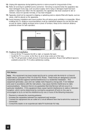
L/MONO R AUDIO 17) Cautions for help. 4 FCC Notice: Note: This equipment has been tested and found to comply with the instructions, may cause harmful interference to radio communications. If this equipment does cause harmful interference to qualified service personnel. The TV will not occur in...equipment generates, uses and can be maintained between the equipment and receiver. - INPUT-4 S-VIDEO OVER VIDEO + VOLUME - Do not tilt the TV towards the left or right, or towards the back. - Increase the separation between the set and the wall, as well as inside a tightly...
L/MONO R AUDIO 17) Cautions for help. 4 FCC Notice: Note: This equipment has been tested and found to comply with the instructions, may cause harmful interference to radio communications. If this equipment does cause harmful interference to qualified service personnel. The TV will not occur in...equipment generates, uses and can be maintained between the equipment and receiver. - INPUT-4 S-VIDEO OVER VIDEO + VOLUME - Do not tilt the TV towards the left or right, or towards the back. - Increase the separation between the set and the wall, as well as inside a tightly...
Instructions
Page 8
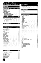
... Lock 54 V1 Smart Input 54 Video Input Label 55 Position Adjustment 56 Power Indicator 56 Video-1 Monitor Out 57 TV Speaker 57 Audio Out 57 Digital-In 58 Digital-In Audio 58 Center CH Input 59 Picture Adjust 60 Picture Settings 60 Adjust Picture Settings 60 Color Temperature 60 Digital Noise Clear... Function 67 Twin 67 Index 68 Freeze 68 Swap 68 Select 68 Power 69 Number Buttons 69 Tune 69 Input 69 TheaterPro D6500K 69 Return+/TV 70 Sound 70 Muting 71 Video Status 71 Natural Cinema 71 Sleep Timer 72 ML/MTS 72 Display 73 C.C 73 Channel 73 Volume 73 Favorite...
... Lock 54 V1 Smart Input 54 Video Input Label 55 Position Adjustment 56 Power Indicator 56 Video-1 Monitor Out 57 TV Speaker 57 Audio Out 57 Digital-In 58 Digital-In Audio 58 Center CH Input 59 Picture Adjust 60 Picture Settings 60 Adjust Picture Settings 60 Color Temperature 60 Digital Noise Clear... Function 67 Twin 67 Index 68 Freeze 68 Swap 68 Select 68 Power 69 Number Buttons 69 Tune 69 Input 69 TheaterPro D6500K 69 Return+/TV 70 Sound 70 Muting 71 Video Status 71 Natural Cinema 71 Sleep Timer 72 ML/MTS 72 Display 73 C.C 73 Channel 73 Volume 73 Favorite...
Instructions
Page 11
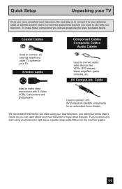
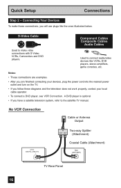
... you have unpacked your television, the next step is to connect it to your antenna/ cable or satellite system and to connect the audio/video devices you want to use plugs like VCRs, DVD players, stereo amplifiers, game consoles, etc. AV CompuLink Cable Used to make ... your new television's many great features. If you're anxious to connect audio/ video devices like the ones illustrated below. To make video connections with your TV. Coaxial Cables Used to connect an external antenna or cable TV system to connect JVC AV CompuLink capable components for an automated home theater.
... you have unpacked your television, the next step is to connect it to your antenna/ cable or satellite system and to connect the audio/video devices you want to use plugs like VCRs, DVD players, stereo amplifiers, game consoles, etc. AV CompuLink Cable Used to make ... your new television's many great features. If you're anxious to connect audio/ video devices like the ones illustrated below. To make video connections with your TV. Coaxial Cables Used to connect an external antenna or cable TV system to connect JVC AV CompuLink capable components for an automated home theater.
Instructions
Page 12
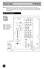
...help assist you connect your television to another device, as well as use the remote to set up your specific TV and remote. Rear Panel Diagram MODELS: HD-52G886 HD-52G786 HD-56G886 HD-56G786 Note: The terminal labeled "SERVICE ONLY", is...AV COMPULINK III VIDEO (DIGITAL) _ AUDIO (DIGITAL) CABLE CARD CENTER CHANNEL INPUT INPUT-2 Y VIDEO L AUDIO R S-VIDEO Pb Pr S-VIDEO L AUDIO R OVER VIDEO L I AUDIO I R OVER Y VIDEO L Pb I AUDIO I R Pr INPUT-3 INPUT-1 i.LINK IN/OUT S400(TS) OPTICAL OUT Digital Audio S-VIDEO VIDEO L AUDIO PC IN (D-SUB) L AUDIO OUTPUT 75Ω (VHF/UHF) ...
...help assist you connect your television to another device, as well as use the remote to set up your specific TV and remote. Rear Panel Diagram MODELS: HD-52G886 HD-52G786 HD-56G886 HD-56G786 Note: The terminal labeled "SERVICE ONLY", is...AV COMPULINK III VIDEO (DIGITAL) _ AUDIO (DIGITAL) CABLE CARD CENTER CHANNEL INPUT INPUT-2 Y VIDEO L AUDIO R S-VIDEO Pb Pr S-VIDEO L AUDIO R OVER VIDEO L I AUDIO I R OVER Y VIDEO L Pb I AUDIO I R Pr INPUT-3 INPUT-1 i.LINK IN/OUT S400(TS) OPTICAL OUT Digital Audio S-VIDEO VIDEO L AUDIO PC IN (D-SUB) L AUDIO OUTPUT 75Ω (VHF/UHF) ...
Instructions
Page 16
... Two-way Splitter OUT OUT (Attachment) Coaxial Cable (Attachment) 75Ω (VHF/UHF) TV Rear Panel 16 Quick Setup Connections Step 2 - S-Video Cable Component Cables Composite Cables Audio Cables Used to connect audio/video devices like the ones illustrated below. Notes: • These connections are examples. •...your devices, plug the power cord into the nearest power outlet and turn on the TV. • If you follow these connections, you have a satellite television system, refer to the satellite TV manual. A DVD player is optional • If you will use plugs like VCRs...
... Two-way Splitter OUT OUT (Attachment) Coaxial Cable (Attachment) 75Ω (VHF/UHF) TV Rear Panel 16 Quick Setup Connections Step 2 - S-Video Cable Component Cables Composite Cables Audio Cables Used to connect audio/video devices like the ones illustrated below. Notes: • These connections are examples. •...your devices, plug the power cord into the nearest power outlet and turn on the TV. • If you follow these connections, you have a satellite television system, refer to the satellite TV manual. A DVD player is optional • If you will use plugs like VCRs...
Instructions
Page 17
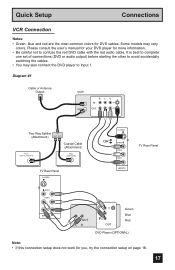
... OUT Two-Way Splitter IN (Attachment) OUT OUT Coaxial Cable (Attachment) ATSC /DIGITAL CABLE IN I 75Ω (VHF/UHF) TV Rear Panel S-VIDEO S-VIDEO OR OVER VIDEO L I AUDIO I R INPUT-3 TV Rear Panel OVER Y VIDEO L Pb I AUDIO I R Pr INPUT-1 AUDIO OUT L R Y PB PR OUT Green Blue Red DVD Player (OPTIONAL) Note: • If this connection setup does not...
... OUT Two-Way Splitter IN (Attachment) OUT OUT Coaxial Cable (Attachment) ATSC /DIGITAL CABLE IN I 75Ω (VHF/UHF) TV Rear Panel S-VIDEO S-VIDEO OR OVER VIDEO L I AUDIO I R INPUT-3 TV Rear Panel OVER Y VIDEO L Pb I AUDIO I R Pr INPUT-1 AUDIO OUT L R Y PB PR OUT Green Blue Red DVD Player (OPTIONAL) Note: • If this connection setup does not...
Instructions
Page 18
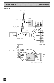
Quick Setup Diagram #2 Cable or Antenna Output Connections Two-Way Splitter IN OUT OUT VCR IN OUT Two-Way Splitter IN (Attachment) OUT OUT Coaxial Cable (Attachment) ATSC /DIGITAL CABLE IN I 75Ω (VHF/UHF) TV Rear Panel S-VIDEO R L V IN OUT S-VIDEO OR OVER VIDEO L I AUDIO I R INPUT-3 TV Rear Panel TV Rear Panel OVER Y VIDEO L Pb I AUDIO I R Pr INPUT-1 AUDIO OUT L R Y PB PR OUT Green Blue Red DVD Player (OPTIONAL) 18
Quick Setup Diagram #2 Cable or Antenna Output Connections Two-Way Splitter IN OUT OUT VCR IN OUT Two-Way Splitter IN (Attachment) OUT OUT Coaxial Cable (Attachment) ATSC /DIGITAL CABLE IN I 75Ω (VHF/UHF) TV Rear Panel S-VIDEO R L V IN OUT S-VIDEO OR OVER VIDEO L I AUDIO I R INPUT-3 TV Rear Panel TV Rear Panel OVER Y VIDEO L Pb I AUDIO I R Pr INPUT-1 AUDIO OUT L R Y PB PR OUT Green Blue Red DVD Player (OPTIONAL) 18
Instructions
Page 19
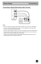
Quick Setup Connections Connecting to Monitor/Recording Output Terminal S-VIDEO VIDEO L AUDIO R MONITOR /REC OUT TV Rear Panel VCR IN OUT OR R L V IN OUT Notes: • When you make this connection, set the Video-1 Monitor Out menu to the S-Video output terminal. &#... images coming from the composite video input terminal. • No signal will be outputted through the Monitor/Recording output terminal when you are receiving Analog TV signal, it can not be outputted to ON. See page 57. • If you are receiving ATSC/Digital Cable signal, it can be outputted to...
Quick Setup Connections Connecting to Monitor/Recording Output Terminal S-VIDEO VIDEO L AUDIO R MONITOR /REC OUT TV Rear Panel VCR IN OUT OR R L V IN OUT Notes: • When you make this connection, set the Video-1 Monitor Out menu to the S-Video output terminal. &#... images coming from the composite video input terminal. • No signal will be outputted through the Monitor/Recording output terminal when you are receiving Analog TV signal, it can not be outputted to ON. See page 57. • If you are receiving ATSC/Digital Cable signal, it can be outputted to...
Instructions
Page 20
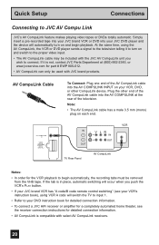
Plug the other CompuLink device. AV COMPULINK III VIDEO (DIGITAL) _ AUDIO (DIGITAL) IN V L R IN OUT OUT TV Rear Panel AV CompuLink VCR Notes: • In order for a completely automated home theater, see your VCR's instruction book), using the AV CompuLink, the VCR...into the AV COMPULINK at (800)-882-2345, or www.jvcservice.com for detailed connection information. • AV CompuLink is not, contact JVC Parts Department at the rear of the television. If the tab is in place, automatic switching will automatically turn on each end. AV CompuLink Cable To Connect: ...
Plug the other CompuLink device. AV COMPULINK III VIDEO (DIGITAL) _ AUDIO (DIGITAL) IN V L R IN OUT OUT TV Rear Panel AV CompuLink VCR Notes: • In order for a completely automated home theater, see your VCR's instruction book), using the AV CompuLink, the VCR...into the AV COMPULINK at (800)-882-2345, or www.jvcservice.com for detailed connection information. • AV CompuLink is not, contact JVC Parts Department at the rear of the television. If the tab is in place, automatic switching will automatically turn on each end. AV CompuLink Cable To Connect: ...
Instructions
Page 21
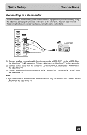
... the camcorder. 2) Connect a white cable from the camcorder LEFT AUDIO OUT, into the LEFT AUDIO IN on the side of the TV. 3) Connect a red cable from the camcorder RIGHT AUDIO OUT, into the RIGHT AUDIO IN on the side of the TV. 21 Connect it to your camcorder is a mono sound model ...it will have only one AUDIO OUT. INPUT MENU INPUT 4 S-VIDEO OPERATE + CHANNEL - You can also connect these using the television's rear input jacks, using...
... the camcorder. 2) Connect a white cable from the camcorder LEFT AUDIO OUT, into the LEFT AUDIO IN on the side of the TV. 3) Connect a red cable from the camcorder RIGHT AUDIO OUT, into the RIGHT AUDIO IN on the side of the TV. 21 Connect it to your camcorder is a mono sound model ...it will have only one AUDIO OUT. INPUT MENU INPUT 4 S-VIDEO OPERATE + CHANNEL - You can also connect these using the television's rear input jacks, using...
Instructions
Page 22
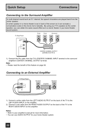
... the surround amplifier's CENTER CHANNEL OUTPUT terminal. Connecting to an External Amplifier TV Rear Panel L AUDIO OUTPUT R Speaker Amplifier Speaker 1) Connect a white cable from the LEFT AUDIO OUTPUT on the back of the TV to your amplifier's manual for more information. • You can obtain...sound effect as in a movie theater in the movie more naturally. TV Rear Panel Front Front Surround CENTER CHANNEL INPUT L AUDIO R CENTER CHANNEL OUTPUT (VARIABLE OUTPUT) 1) Connect the Pin cable from the TV's CENTER CHANNEL INPUT terminal to the Surround Amplifier In multi-channel sound...
... the surround amplifier's CENTER CHANNEL OUTPUT terminal. Connecting to an External Amplifier TV Rear Panel L AUDIO OUTPUT R Speaker Amplifier Speaker 1) Connect a white cable from the LEFT AUDIO OUTPUT on the back of the TV to your amplifier's manual for more information. • You can obtain...sound effect as in a movie theater in the movie more naturally. TV Rear Panel Front Front Surround CENTER CHANNEL INPUT L AUDIO R CENTER CHANNEL OUTPUT (VARIABLE OUTPUT) 1) Connect the Pin cable from the TV's CENTER CHANNEL INPUT terminal to the Surround Amplifier In multi-channel sound...
Instructions
Page 23
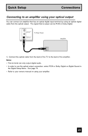
... input terminal by using your amplifier. 23 i.LINK IN/OUT S400(TS) TV Rear Panel OPTICAL OUT Digital Audio Amplifier 1) Connect the optical cable from the optical output. See page 79. • Refer to the back of the TV to your owners manual on Digital Sound in the Digital Setup Menu. Quick... Setup Connections Connecting to an amplifier using your optical output You can connect an amplifier that is output can only output digital audio. • In order to use the ...
... input terminal by using your amplifier. 23 i.LINK IN/OUT S400(TS) TV Rear Panel OPTICAL OUT Digital Audio Amplifier 1) Connect the optical cable from the optical output. See page 79. • Refer to the back of the TV to your owners manual on Digital Sound in the Digital Setup Menu. Quick... Setup Connections Connecting to an amplifier using your optical output You can connect an amplifier that is output can only output digital audio. • In order to use the ...
Instructions
Page 24
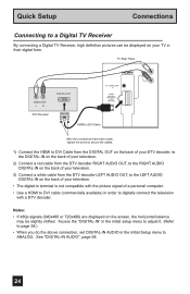
... may be displayed on the back of your TV in their digital form. Quick Setup Connections Connecting to a Digital TV Receiver By connecting a Digital TV Receiver, high definition pictures can be slightly shifted. TV Rear Panel AUDIO OUT LR DTV Decoder DIGITAL OUT AV COMPULINK ...III VIDEO (DIGITAL) _ AUDIO (DIGITAL) HDMI to DVI Cable L AUDIO R After the connections have been...
... may be displayed on the back of your TV in their digital form. Quick Setup Connections Connecting to a Digital TV Receiver By connecting a Digital TV Receiver, high definition pictures can be slightly shifted. TV Rear Panel AUDIO OUT LR DTV Decoder DIGITAL OUT AV COMPULINK ...III VIDEO (DIGITAL) _ AUDIO (DIGITAL) HDMI to DVI Cable L AUDIO R After the connections have been...
Instructions
Page 25
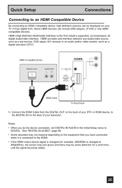
...changed (for a short time until the signal becomes stable. 25 HDMI provides and interface between any HDMI compatible devices. See "DIGITAL-IN AUDIO", page 58. • Some decoders may not respond depending on the equipment that you do the above connection, set -top box, DVD... for example, 480i/60Hz is the first industry supported, uncompressed, all digital audio/video interface. HDMI Compatible Device DIGITAL OUT AUDIO OUT LR AV COMPULINK III VIDEO (DIGITAL) _ AUDIO (DIGITAL) L AUDIO R HDMI Cable TV Rear Panel 1) Connect the HDMI Cable from the DIGITAL OUT on the back of...
...changed (for a short time until the signal becomes stable. 25 HDMI provides and interface between any HDMI compatible devices. See "DIGITAL-IN AUDIO", page 58. • Some decoders may not respond depending on the equipment that you do the above connection, set -top box, DVD... for example, 480i/60Hz is the first industry supported, uncompressed, all digital audio/video interface. HDMI Compatible Device DIGITAL OUT AUDIO OUT LR AV COMPULINK III VIDEO (DIGITAL) _ AUDIO (DIGITAL) L AUDIO R HDMI Cable TV Rear Panel 1) Connect the HDMI Cable from the DIGITAL OUT on the back of...
Instructions
Page 26
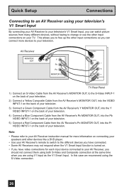
In this case we recommend using V1 Input as the V1 Smart Input. AV Receiver MONITOR OUT Y PB PR MONITOR OUT S-VIDEO OVER Y VIDEO L Pb I AUDIO I R Pr INPUT-1 TV Rear Panel 1) Connect an S-Video Cable from the AV Receiver's PR MONITOR OUT, into the Pr VIDEO INPUT-1 on the back of your television. 5) Connect... VIDEO INPUT-1 on the back of your television. Note: • Please refer to your AV Receiver instruction manual for each input device connected to your TV. This allows you to free up the other input connections so you are using the S-Video connection. 26
In this case we recommend using V1 Input as the V1 Smart Input. AV Receiver MONITOR OUT Y PB PR MONITOR OUT S-VIDEO OVER Y VIDEO L Pb I AUDIO I R Pr INPUT-1 TV Rear Panel 1) Connect an S-Video Cable from the AV Receiver's PR MONITOR OUT, into the Pr VIDEO INPUT-1 on the back of your television. 5) Connect... VIDEO INPUT-1 on the back of your television. Note: • Please refer to your AV Receiver instruction manual for each input device connected to your TV. This allows you to free up the other input connections so you are using the S-Video connection. 26
Instructions
Page 27
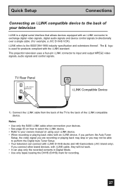
... will not work. • It can connect with i.LINK D-VHS decks and HD-Camcorders (JVC brand only). Notes: • Use only the S400 i.LINK cable when connection your devices.... on using your television i.LINK is used for recording. 27 TV Rear Panel i.LINK IN/OUT S400(TS) OPTICAL OUT Digital Audio i.LINK Compatible Device 1) Connect the i.LINK cable from the ...back of the i.LINK compatible device. i.LINK refers to the back of the TV to the IEEE1394-1995 industry specification and extensions thereof. This projection...
... will not work. • It can connect with i.LINK D-VHS decks and HD-Camcorders (JVC brand only). Notes: • Use only the S400 i.LINK cable when connection your devices.... on using your television i.LINK is used for recording. 27 TV Rear Panel i.LINK IN/OUT S400(TS) OPTICAL OUT Digital Audio i.LINK Compatible Device 1) Connect the i.LINK cable from the ...back of the i.LINK compatible device. i.LINK refers to the back of the TV to the IEEE1394-1995 industry specification and extensions thereof. This projection...
Instructions
Page 28
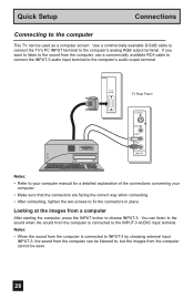
... computer cannot be used as a computer screen. Quick Setup Connections Connecting to fix the connectors in place. PC IN (D-SUB) TV Rear Panel S-VIDEO OVER VIDEO L I AUDIO I R INPUT-3 Notes: • Refer to your computer manual for a detailed explanation of the connections concerning your computer. &#... images from the computer, use a commercially available RCA cable to connect the INPUT-3 audio input terminal to the INPUT-3 AUDIO input terminal. Use a commercially available D-SUB cable to connect the TV's PC INPUT terminal to choose INPUT-3. If you want to listen to the sound ...
... computer cannot be used as a computer screen. Quick Setup Connections Connecting to fix the connectors in place. PC IN (D-SUB) TV Rear Panel S-VIDEO OVER VIDEO L I AUDIO I R INPUT-3 Notes: • Refer to your computer manual for a detailed explanation of the connections concerning your computer. &#... images from the computer, use a commercially available RCA cable to connect the INPUT-3 audio input terminal to the INPUT-3 AUDIO input terminal. Use a commercially available D-SUB cable to connect the TV's PC INPUT terminal to choose INPUT-3. If you want to listen to the sound ...

Instructions
Page 34
...and press PLAY. 34 VCR Codes Admiral 035 Aiwa 027, 032, 095 Akai 029, 072, 073, 074 Audio Dynamic 003, 005 Bell & Howell 063, 071 Broksonic 020, 026, 094 Canon 023, 025 CCE 043... Find the VCR brand from the list of codes shown below. 2) Slide the first 2-way selector switch to "TV" and the other 2-way selector switch to "VCR". 3) Press and hold down the REC button on page 36..., 081, 000, 001 Hitachi 023, 045, 058, 093, 027, 081 Instant Replay 024, 023 Jensen 003 JVC 003, 004, 005, 000, 001, 002, 006, 007 VCR Marantz Marta Memorex MGA Minolta Mitsubishi Multitech NEC ...
...and press PLAY. 34 VCR Codes Admiral 035 Aiwa 027, 032, 095 Akai 029, 072, 073, 074 Audio Dynamic 003, 005 Bell & Howell 063, 071 Broksonic 020, 026, 094 Canon 023, 025 CCE 043... Find the VCR brand from the list of codes shown below. 2) Slide the first 2-way selector switch to "TV" and the other 2-way selector switch to "VCR". 3) Press and hold down the REC button on page 36..., 081, 000, 001 Hitachi 023, 045, 058, 093, 027, 081 Instant Replay 024, 023 Jensen 003 JVC 003, 004, 005, 000, 001, 002, 006, 007 VCR Marantz Marta Memorex MGA Minolta Mitsubishi Multitech NEC ...

Instructions
Page 35
... the DVD player's remote. DVD Player Aiwa Apex Bose Denon Funai Go-Video Harman Kardon Hitachi JVC Kenwood KLH Konka Koss Codes 043 040, 054, 055 058 020, 037 038 032 053 031... 000 035, 020 051 039 050 DVD Player Mintek Mitsubishi Next Base Onkyo Oritron Panasonic Philips Pioneer Polk Audio Raite RCA Sampo Samsung Codes 057 025 056 041, 052 044 020 023, 036 022 036 033 021, ... Find the DVD player brand from the list of codes shown below. 2) Slide the first 2-way selector switch to "TV" and the other 2-way selector switch to the first code, try the others listed. If it does not respond to...
... the DVD player's remote. DVD Player Aiwa Apex Bose Denon Funai Go-Video Harman Kardon Hitachi JVC Kenwood KLH Konka Koss Codes 043 040, 054, 055 058 020, 037 038 032 053 031... 000 035, 020 051 039 050 DVD Player Mintek Mitsubishi Next Base Onkyo Oritron Panasonic Philips Pioneer Polk Audio Raite RCA Sampo Samsung Codes 057 025 056 041, 052 044 020 023, 036 022 036 033 021, ... Find the DVD player brand from the list of codes shown below. 2) Slide the first 2-way selector switch to "TV" and the other 2-way selector switch to the first code, try the others listed. If it does not respond to...
Instructions
Page 39
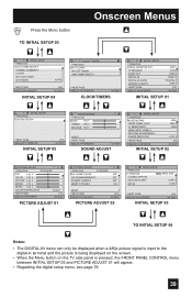
...picture signal is input to the digital-in terminal and the picture is being displayed on the screen. • When the Menu button on the TV side panel is pressed, the FRONT PANEL CONTROL menu between INITIAL SETUP 05 and PICTURE ADJUST 01 will appear. • Regarding the digital setup... CLOCK ON / OFF TIMER LAMP TIMER RESET NEXT PAGE SELECT OPERATE MENU EXIT CLOCK/TIMERS INITIAL SETUP PREVIOUS VIDEO-1MONITOR OUT TV SPEAKER AUDIO OUT DIGITAL-IN DIGITAL-IN AUDIO CENTER CH INPUT NEXT PAGE SELECT OPERATE OFF ON VARI SIZE1 DIGITAL OFF (1/5) MENU EXIT INITIAL SETUP 01 INITIAL SETUP PREVIOUS ...
...picture signal is input to the digital-in terminal and the picture is being displayed on the screen. • When the Menu button on the TV side panel is pressed, the FRONT PANEL CONTROL menu between INITIAL SETUP 05 and PICTURE ADJUST 01 will appear. • Regarding the digital setup... CLOCK ON / OFF TIMER LAMP TIMER RESET NEXT PAGE SELECT OPERATE MENU EXIT CLOCK/TIMERS INITIAL SETUP PREVIOUS VIDEO-1MONITOR OUT TV SPEAKER AUDIO OUT DIGITAL-IN DIGITAL-IN AUDIO CENTER CH INPUT NEXT PAGE SELECT OPERATE OFF ON VARI SIZE1 DIGITAL OFF (1/5) MENU EXIT INITIAL SETUP 01 INITIAL SETUP PREVIOUS ...
