
VC-P840 cable connection to HD200 Series manual (enables use of studio viewfinder without studio sled)
Page 1
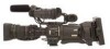
The Tally and Preview signal is located on the Camera's VF menu setting. This cable does not provide power to the VF-HP840U via serial communication. Owners of the GY-HD250U and GY-HD200UB also have the choice of using the high definition VF-HP840U in non studio ...approximately 2ft long. Remove two screws from the camera to the camcorder. Cable VC-P840U Product Information Manual Product Feature The VC-P840U provides a direct video signal connection between the JVC's HD studio Viewfinder (VF-HP840U) and the GY-HD250U/GY-HD200UB. User Benefit This cable gives the Studio ...
The Tally and Preview signal is located on the Camera's VF menu setting. This cable does not provide power to the VF-HP840U via serial communication. Owners of the GY-HD250U and GY-HD200UB also have the choice of using the high definition VF-HP840U in non studio ...approximately 2ft long. Remove two screws from the camera to the camcorder. Cable VC-P840U Product Information Manual Product Feature The VC-P840U provides a direct video signal connection between the JVC's HD studio Viewfinder (VF-HP840U) and the GY-HD250U/GY-HD200UB. User Benefit This cable gives the Studio ...

VC-P840 cable connection to HD200 Series manual (enables use of studio viewfinder without studio sled)
Page 2
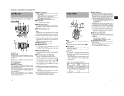
...; VC-Y250US - VC-P840U and VF-HP840U System Diagrams Power applied to camera via a battery mount, then the following additional components are required to mount and power the VF-HP840U: • SA-K840 - available from the camera mount's D tap - Y power cable used to apply power to power ...the VF-HP840U from Anton Bauer http://www.antonbauer.com Power Applied to camera via a 4 pin XLR When power is applied to the camera via battery mount When power is applied to the camera's 4 pin XLR input, the following additional components are required to mount and ...
...; VC-Y250US - VC-P840U and VF-HP840U System Diagrams Power applied to camera via a battery mount, then the following additional components are required to mount and power the VF-HP840U: • SA-K840 - available from the camera mount's D tap - Y power cable used to apply power to power ...the VF-HP840U from Anton Bauer http://www.antonbauer.com Power Applied to camera via a 4 pin XLR When power is applied to the camera via battery mount When power is applied to the camera's 4 pin XLR input, the following additional components are required to mount and ...

GY-HD200U Owner's Manual
Page 1
...carefully to ensure the best possible performance. Before operating this information for purchasing this JVC product. Serial No. * The illustration shows the GY-HD200U/ GY-HD200E/GY-HD201E HD CAMERA RECORDER with the provided lens, viewfinder and microphone attached. which is located on the... Enter below the Serial No. Model No. © 2006 Victor Company of Japan, Limited HD CAMERA RECORDER GY-HD200U/CHU INSTRUCTIONS GY-HD200E/CHE GY-HD201E/CHE E INTRODUCTION CONTROLS, INDICATORS AND CONNECTORS PREPARATIONS PREPARATIONS FOR OPERATION SETTING AND ADJUSTMENTS BEFORE SHOOTING ...
...carefully to ensure the best possible performance. Before operating this information for purchasing this JVC product. Serial No. * The illustration shows the GY-HD200U/ GY-HD200E/GY-HD201E HD CAMERA RECORDER with the provided lens, viewfinder and microphone attached. which is located on the... Enter below the Serial No. Model No. © 2006 Victor Company of Japan, Limited HD CAMERA RECORDER GY-HD200U/CHU INSTRUCTIONS GY-HD200E/CHE GY-HD201E/CHE E INTRODUCTION CONTROLS, INDICATORS AND CONNECTORS PREPARATIONS PREPARATIONS FOR OPERATION SETTING AND ADJUSTMENTS BEFORE SHOOTING ...

GY-HD200U Owner's Manual
Page 3
...Replace only with national legislation. (Business users) If you wish to dispose of this product, please visit our web page www.jvc-europe.com to obtain information about collection point and recycling of electrical and electronic equipment for the treatment of this product correctly, you...as vases, shall be placed close to the apparatus. e.g. Dear Customer, This apparatus is : JVC Technology Centre Europe GmbH P.O. The apparatus shall not be used in the following length: Camera Port Cable DC IN Exclusive Cable VIDEO Coaxial Cable Y, PB, PR Coaxial Cable AUDIO INPUT1, INPUT2...
...Replace only with national legislation. (Business users) If you wish to dispose of this product, please visit our web page www.jvc-europe.com to obtain information about collection point and recycling of electrical and electronic equipment for the treatment of this product correctly, you...as vases, shall be placed close to the apparatus. e.g. Dear Customer, This apparatus is : JVC Technology Centre Europe GmbH P.O. The apparatus shall not be used in the following length: Camera Port Cable DC IN Exclusive Cable VIDEO Coaxial Cable Y, PB, PR Coaxial Cable AUDIO INPUT1, INPUT2...

GY-HD200U Owner's Manual
Page 4
... A symbol can be played back (simple playback). The following phenomena may infringe on Mini DV videocassettes. DV for purchasing the JVC HD CAMERA RECORDER. There are not used in the SP mode. Component output is converted to HDV/DV devices. 3 DVCAM is not ... HDV 1080i (1080 effective scan lines, interlaced scan) This device supports HDV 720p format. (HDV 720p) HDV and are for highquality picture 1/3" 3-CCD with the GY-HD200CHU, GY- It can select this device. • Recording check function for convenient recording review function • Camera section designed...
... A symbol can be played back (simple playback). The following phenomena may infringe on Mini DV videocassettes. DV for purchasing the JVC HD CAMERA RECORDER. There are not used in the SP mode. Component output is converted to HDV/DV devices. 3 DVCAM is not ... HDV 1080i (1080 effective scan lines, interlaced scan) This device supports HDV 720p format. (HDV 720p) HDV and are for highquality picture 1/3" 3-CCD with the GY-HD200CHU, GY- It can select this device. • Recording check function for convenient recording review function • Camera section designed...
GY-HD200U Owner's Manual
Page 5
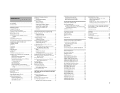
...and Time 42 Displaying the Time and Date on the Screen 42 Displaying Time Code 43 Time code input entered the IEEE1394 connector (GY-HD200U/GY-HD201E only 43 Presetting and Recording of Time Code 44 Setting 44 Presetting time code data 45 Presetting user's bit data 45 Zero...70 Setting Menu Screens 72 TOP MENU Screen 73 VIDEO FORMAT[1/2] Menu Screen 74 VIDEO FORMAT[2/2] Menu Screen 76 CAMERA OPERATION Menu Screen 77 CAMERA PROCESS[1/2] Menu Screen 78 CAMERA PROCESS[2/2] Menu Screen 79 ADVANCED PROCESS Menu Screen 80 COLOR MATRIX ADJUST Menu Screen 81 SKIN COLOR ADJUST Menu Screen...
...and Time 42 Displaying the Time and Date on the Screen 42 Displaying Time Code 43 Time code input entered the IEEE1394 connector (GY-HD200U/GY-HD201E only 43 Presetting and Recording of Time Code 44 Setting 44 Presetting time code data 45 Presetting user's bit data 45 Zero...70 Setting Menu Screens 72 TOP MENU Screen 73 VIDEO FORMAT[1/2] Menu Screen 74 VIDEO FORMAT[2/2] Menu Screen 76 CAMERA OPERATION Menu Screen 77 CAMERA PROCESS[1/2] Menu Screen 78 CAMERA PROCESS[2/2] Menu Screen 79 ADVANCED PROCESS Menu Screen 80 COLOR MATRIX ADJUST Menu Screen 81 SKIN COLOR ADJUST Menu Screen...

GY-HD200U Owner's Manual
Page 6
.... Therefore, the data in the viewfinder when switching between 11 V and 15 V DC. Precautions for Use of wireless microphone near the camera When a wireless microphone or wireless microphone tuner is used immediately after use will collect dirt, wear out and deteriorate as required. use of... when the built-in head cleaner that the power is between the playback picture and the EE picture. • Use this device at your nearest JVC-authorized service agent. Be sure to the running time. Block Noise • Please use of failure. G E ing heads) Tape guides, rollers ...
.... Therefore, the data in the viewfinder when switching between 11 V and 15 V DC. Precautions for Use of wireless microphone near the camera When a wireless microphone or wireless microphone tuner is used immediately after use will collect dirt, wear out and deteriorate as required. use of... when the built-in head cleaner that the power is between the playback picture and the EE picture. • Use this device at your nearest JVC-authorized service agent. Be sure to the running time. Block Noise • Please use of failure. G E ing heads) Tape guides, rollers ...

GY-HD200U Owner's Manual
Page 7
...Also it to the beginning before placing a cassette into condensation and then to be dissolved. • To prevent condensation When moving the camera under conditions where the temperature of the new environment before using . • Pay attention to condensation even before using it becomes unable..., etc. In an extremely cold place, the condensation could freeze and turn into water droplets. Videocassette to be Used • Use JVC's videocassette tapes marked with its tape not being overwritten. • To record on end. It is referred to REC. When this occurs...
...Also it to the beginning before placing a cassette into condensation and then to be dissolved. • To prevent condensation When moving the camera under conditions where the temperature of the new environment before using . • Pay attention to condensation even before using it becomes unable..., etc. In an extremely cold place, the condensation could freeze and turn into water droplets. Videocassette to be Used • Use JVC's videocassette tapes marked with its tape not being overwritten. • To record on end. It is referred to REC. When this occurs...
GY-HD200U Owner's Manual
Page 8
... Zebra patterns are not indicated while the color bar or VTR playback picture is pressed. X See "Attaching the Zoom Lens" on page 50. When the camera control unit is connected, you press this ring in the macro mode. X See "Back Focus Adjustment" on page 33. 11 dMacro focusing ring (for ...page 15 is not activated in the SWITCH MODE menu screen, you can be changed with the ZEBRA setting in accordance with the GY-HD200CHU, GYHD200CHE or the GY-HD201CHE. When the tape has run out, or the VTR enters the warning mode, it possible to the OFF position when released....
... Zebra patterns are not indicated while the color bar or VTR playback picture is pressed. X See "Attaching the Zoom Lens" on page 50. When the camera control unit is connected, you press this ring in the macro mode. X See "Back Focus Adjustment" on page 33. 11 dMacro focusing ring (for ...page 15 is not activated in the SWITCH MODE menu screen, you can be changed with the ZEBRA setting in accordance with the GY-HD200CHU, GYHD200CHE or the GY-HD201CHE. When the tape has run out, or the VTR enters the warning mode, it possible to the OFF position when released....

GY-HD200U Owner's Manual
Page 9
...showing the whether this device is also used when recording scenes one after another , the time codes become discontinuous at the transition points between camera mode and VTR mode. Plug in an earphone or headphone with the AUDIO MONITOR item on the AUDIO/MIC[2/2] menu screen and MONITOR SELECT ... or the VTR playback picture. Set to this position to record with the GYHD200U/GY-HD201E.) • When the power is turned on page 90. 5[CAM/VTR] Camera/VTR mode switch button Each time you to display time code values. If this button, the mode switches between scenes. : The ...
...showing the whether this device is also used when recording scenes one after another , the time codes become discontinuous at the transition points between camera mode and VTR mode. Plug in an earphone or headphone with the AUDIO MONITOR item on the AUDIO/MIC[2/2] menu screen and MONITOR SELECT ... or the VTR playback picture. Set to this position to record with the GYHD200U/GY-HD201E.) • When the power is turned on page 90. 5[CAM/VTR] Camera/VTR mode switch button Each time you to display time code values. If this button, the mode switches between scenes. : The ...

GY-HD200U Owner's Manual
Page 10
...white balance in WHITE PAINT/ on the WHITE BALANCE menu screen. (Available only when this door is 1080i. HDV/DV : Turns off . • When this light in the main body of field shallower...(1/4ND) 2 : Cuts the light intensity to approximately 1/16. (1/16ND) When you change the setting. X See "Camera Settings" on the LCD monitor. If white balance is DV. A : Switch into white balance mode memorized in the ...DV input sound can be EE monitored. (HDV/DV signal input is possible with the GY-HD200U/GY-HD201E.) The sound to be changed when this switch. iLCD door LCD monitor door....
...white balance in WHITE PAINT/ on the WHITE BALANCE menu screen. (Available only when this door is 1080i. HDV/DV : Turns off . • When this light in the main body of field shallower...(1/4ND) 2 : Cuts the light intensity to approximately 1/16. (1/16ND) When you change the setting. X See "Camera Settings" on the LCD monitor. If white balance is DV. A : Switch into white balance mode memorized in the ...DV input sound can be EE monitored. (HDV/DV signal input is possible with the GY-HD200U/GY-HD201E.) The sound to be changed when this switch. iLCD door LCD monitor door....

GY-HD200U Owner's Manual
Page 11
... connector using them. 16 a b c d a[IEEE1394] IEEE1394 switch Set according to the image format of the input/output signal and playback signal of this camera can select the normal input level for U model) • Set ANALOG OUT CHAR. item on page 68. The CH-2 audio from entering the internal parts...a battery is installed and a cable is connected to DV format signals in the VTR mode. (HDV/DV signal input is possible with the GYHD200U/GY-HD201E.) MEMO Alarm sound is used to select the input sound signal from this terminal. 9[AUDIO OUTPUT CH-1/CH-2] Audio output connector (RCA) Output ...
... connector using them. 16 a b c d a[IEEE1394] IEEE1394 switch Set according to the image format of the input/output signal and playback signal of this camera can select the normal input level for U model) • Set ANALOG OUT CHAR. item on page 68. The CH-2 audio from entering the internal parts...a battery is installed and a cable is connected to DV format signals in the VTR mode. (HDV/DV signal input is possible with the GYHD200U/GY-HD201E.) MEMO Alarm sound is used to select the input sound signal from this terminal. 9[AUDIO OUTPUT CH-1/CH-2] Audio output connector (RCA) Output ...

GY-HD200U Owner's Manual
Page 12
...DV signal from the monitoring speaker. It flashes when the mode is being changed. (HDV/DV signal input is possible with the GY-HD200U, GY-HD201E.) g[FULL AUTO] Full auto shooting (FAS) switch This is the ON/OFF switch for FAS mode. • During FAS... • Pressing this button during the eject operation. CONTROLS, INDICATORS AND CONNECTORS Top Section 5 6 4 3 2 1 d e f g 7 8 9 0 l a b h i j k c 1Viewfinder Displays the camera image and the playback picture. 2Eyepiece Ensures that ambient light does not reach the viewfinder screen or falls into the eye of the cameraman. 3Eyepiece...
...DV signal from the monitoring speaker. It flashes when the mode is being changed. (HDV/DV signal input is possible with the GY-HD200U, GY-HD201E.) g[FULL AUTO] Full auto shooting (FAS) switch This is the ON/OFF switch for FAS mode. • During FAS... • Pressing this button during the eject operation. CONTROLS, INDICATORS AND CONNECTORS Top Section 5 6 4 3 2 1 d e f g 7 8 9 0 l a b h i j k c 1Viewfinder Displays the camera image and the playback picture. 2Eyepiece Ensures that ambient light does not reach the viewfinder screen or falls into the eye of the cameraman. 3Eyepiece...

GY-HD200U Owner's Manual
Page 13
... also has various output terminals. (Composite, analog component, IEEE1394) During recording and playback, image formats from the IEEE1394 Terminal (Only with the GY-HD200U and GY-HD201E) Recording (IEEE1394 In) HDV DV 720/60p 720/30p 720/50p 720/25p 720/24p 480/60p 576/50p 480/60i U model ... 480/60i U model only DV-24P 480/60i(24p) DV-24PA 480/60i(24p) E model only DV-50I DV-25P 576/50i 576/50i(25p) [1080I CAMERA] menu item Frame rate 60/30 ON 50/25 Rec on Tape q q q q q q q q q q Rec on Tape N/A N/A IEEE1394 Out q q q q q q q q q q IEEE1394 Out N/A N/A Component Out (EE Out) ...
... also has various output terminals. (Composite, analog component, IEEE1394) During recording and playback, image formats from the IEEE1394 Terminal (Only with the GY-HD200U and GY-HD201E) Recording (IEEE1394 In) HDV DV 720/60p 720/30p 720/50p 720/25p 720/24p 480/60p 576/50p 480/60i U model ... 480/60i U model only DV-24P 480/60i(24p) DV-24PA 480/60i(24p) E model only DV-50I DV-25P 576/50i 576/50i(25p) [1080I CAMERA] menu item Frame rate 60/30 ON 50/25 Rec on Tape q q q q q q q q q q Rec on Tape N/A N/A IEEE1394 Out q q q q q q q q q q IEEE1394 Out N/A N/A Component Out (EE Out) ...

GY-HD200U Owner's Manual
Page 14
...] HEADER REC is running HEADER REC FOCUS ASSIST was turned ON/OFF Time code was set to OFF.) STATUS button 22 Status Screens in the Camera Mode 1 0 266S DD 9 8 7 6 5 4 2 3 STATUS 0 Screen STATUS 0 1 Event Indication When the Gain or Shutter Speed is changed manually, the setting... the viewfinder by holding down the DISPLAY button for about 3 seconds at the time the change is displayed in the VTR mode. • CAMERA MODE (display example) STATUS 0 STATUS 1 DISPLAY button „ Status screens (screens for the following character displays. CONTROLS, INDICATORS AND CONNECTORS...
...] HEADER REC is running HEADER REC FOCUS ASSIST was turned ON/OFF Time code was set to OFF.) STATUS button 22 Status Screens in the Camera Mode 1 0 266S DD 9 8 7 6 5 4 2 3 STATUS 0 Screen STATUS 0 1 Event Indication When the Gain or Shutter Speed is changed manually, the setting... the viewfinder by holding down the DISPLAY button for about 3 seconds at the time the change is displayed in the VTR mode. • CAMERA MODE (display example) STATUS 0 STATUS 1 DISPLAY button „ Status screens (screens for the following character displays. CONTROLS, INDICATORS AND CONNECTORS...

GY-HD200U Owner's Manual
Page 15
... LCD Monitor and in the Viewfinder (Cont'd) Setting Status Contents of Indications FF/REW button was pressed in CAMERA SWITCH TO VTR MODE mode REC/VTR trigger button was pressed when 1080I REC INVALID 1080I CAMERA in the VIDEO FORMAT[1/2] menu screen was set to be regarded only as the display style are set...
... LCD Monitor and in the Viewfinder (Cont'd) Setting Status Contents of Indications FF/REW button was pressed in CAMERA SWITCH TO VTR MODE mode REC/VTR trigger button was pressed when 1080I REC INVALID 1080I CAMERA in the VIDEO FORMAT[1/2] menu screen was set to be regarded only as the display style are set...

GY-HD200U Owner's Manual
Page 16
...: 0.82° to 359.4°, 25p: 0.85° to 48 K. (Audio is recorded with the F.NO/IRIS IND. STATUS 2 Screen STATUS 2 This screen displays the camera setup statuses. Item Contents 5 Audio sampling frequency in- 32 K : Indicated when the AUDIO MODE item on the AUDIO/MIC[1/2] menu screen is set to 32...
...: 0.82° to 359.4°, 25p: 0.85° to 48 K. (Audio is recorded with the F.NO/IRIS IND. STATUS 2 Screen STATUS 2 This screen displays the camera setup statuses. Item Contents 5 Audio sampling frequency in- 32 K : Indicated when the AUDIO MODE item on the AUDIO/MIC[1/2] menu screen is set to 32...

GY-HD200U Owner's Manual
Page 18
... button, the display mode is cancelled by the LCD monitor open/close less than 40° 31 TOP MENU screen (Camera mode) Safety Zone Indication (Camera mode only) The indication of the operation are displayed during the auto white balance adjustment operation. OFF ON OFF ON OFF... for making various settings. CONTROLS, INDICATORS AND CONNECTORS Indications on the LCD Monitor and in the Viewfinder (Cont'd) Auto White Balance Indication (Camera mode only) The AUTO WHITE indication and the result of the following alarm messages are displayed while the STATUS (0, 1, 4) screen is shown...
... button, the display mode is cancelled by the LCD monitor open/close less than 40° 31 TOP MENU screen (Camera mode) Safety Zone Indication (Camera mode only) The indication of the operation are displayed during the auto white balance adjustment operation. OFF ON OFF ON OFF... for making various settings. CONTROLS, INDICATORS AND CONNECTORS Indications on the LCD Monitor and in the Viewfinder (Cont'd) Auto White Balance Indication (Camera mode only) The AUTO WHITE indication and the result of the following alarm messages are displayed while the STATUS (0, 1, 4) screen is shown...

GY-HD200U Owner's Manual
Page 20
...clamp 7 on a tripod. 1. Open the SD memory card cover. 2. X See page 98. Attaching the Tripod Base (Optional) Use the optional tripod base to place the camera on page 14. CAUTION • The front base mount may cause this device to become detached and to 2 GB • You can save and call... up menu settings and camera settings for this device. Front mount clip 3. Lock lever 3. Close the SD memory card cover. About SD Memory Cards • When you can write-...
...clamp 7 on a tripod. 1. Open the SD memory card cover. 2. X See page 98. Attaching the Tripod Base (Optional) Use the optional tripod base to place the camera on page 14. CAUTION • The front base mount may cause this device to become detached and to 2 GB • You can save and call... up menu settings and camera settings for this device. Front mount clip 3. Lock lever 3. Close the SD memory card cover. About SD Memory Cards • When you can write-...

GY-HD200U Owner's Manual
Page 21
... the time code data. However, it gradually discharges while this device even if the built-in battery is not used . „ GY-HD200U Use an Anton Bauer battery. „GY-HD200E/GY-HD201E Use an IDX (Endura) battery. Power is supplied to the DC OUTPUT connector of the AC adapter and the DC... POWER switch of the DC cable as shown in which case the set to OFF, connect the DC cable to the VTR section and the camera. Battery will be properly attached if guide pins are reset. After making sure that the power switches of this device and of the AC adapter...
... the time code data. However, it gradually discharges while this device even if the built-in battery is not used . „ GY-HD200U Use an Anton Bauer battery. „GY-HD200E/GY-HD201E Use an IDX (Endura) battery. Power is supplied to the DC OUTPUT connector of the AC adapter and the DC... POWER switch of the DC cable as shown in which case the set to OFF, connect the DC cable to the VTR section and the camera. Battery will be properly attached if guide pins are reset. After making sure that the power switches of this device and of the AC adapter...


