
User Guide
Page 2
... accompanying the appliance. WARNING: CAUTION: TO PREVENT FIRE OR SHOCK HAZARDS, DO NOT EXPOSE THIS TV SET TO RAIN OR MOISTURE. Changes or modifications not approved by JVC could void the warranty. * When you don't use this TV set for a long period of time, be sure to disconnect both the power plug from...
... accompanying the appliance. WARNING: CAUTION: TO PREVENT FIRE OR SHOCK HAZARDS, DO NOT EXPOSE THIS TV SET TO RAIN OR MOISTURE. Changes or modifications not approved by JVC could void the warranty. * When you don't use this TV set for a long period of time, be sure to disconnect both the power plug from...
User Guide
Page 3
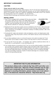
...cord is equipped with respect to proper grounding of the mast and supporting structure, grounding of antenna discharge unit, connection requirements for this TV set near swimming pool, etc. 6 If an outside antenna is wider than the other components that contain lead. Should you are ...plug fully into the power outlet only one blade of the National Electrical Code provides information with a polarized AC line plug (one way. This TV set . They may result in a shock or fire hazard. 5 Do not use can perform many useful functions. IMPORTANT SAFEGUARDS CAUTION: Please...
...cord is equipped with respect to proper grounding of the mast and supporting structure, grounding of antenna discharge unit, connection requirements for this TV set near swimming pool, etc. 6 If an outside antenna is wider than the other components that contain lead. Should you are ...plug fully into the power outlet only one blade of the National Electrical Code provides information with a polarized AC line plug (one way. This TV set . They may result in a shock or fire hazard. 5 Do not use can perform many useful functions. IMPORTANT SAFEGUARDS CAUTION: Please...

User Guide
Page 4
...Use only a cart or stand recommended by the manufacturer. Therefore: - Some internal parts carry hazardous voltages and contact can fall into the TV set from touching such power lines or circuits as contact with them might be fatal. Never cover the openings with a cloth or other ...electric light or power circuits, or where it on a sloping shelf unless properly secured. - Never place a TV set manufacturer. - Wall or shelf mounting should follow the manufacturer's instructions, and should use liquid or an aerosol cleaner. 12 Never add accessories ...
...Use only a cart or stand recommended by the manufacturer. Therefore: - Some internal parts carry hazardous voltages and contact can fall into the TV set from touching such power lines or circuits as contact with them might be fatal. Never cover the openings with a cloth or other ...electric light or power circuits, or where it on a sloping shelf unless properly secured. - Never place a TV set manufacturer. - Wall or shelf mounting should follow the manufacturer's instructions, and should use liquid or an aerosol cleaner. 12 Never add accessories ...
User Guide
Page 5
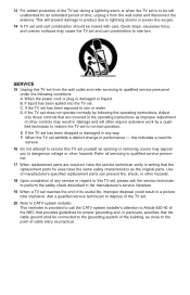
..., have the same safety characteristics as improper adjustment of other hazards. 18 Upon completion of any way. If liquid has been spilled into the TV set from the wall outlet and disconnect the antenna. Adjust only those controls that the cable ground shall be connected to the grounding system of... in performance - Quick stops, excessive force, and uneven surfaces may expose you to overturn. 13 For added protection of the TV set during a lightning storm or when the TV set is to be left unattended for an extended period of time, unplug it from the wall outlet and refer servicing to...
..., have the same safety characteristics as improper adjustment of other hazards. 18 Upon completion of any way. If liquid has been spilled into the TV set from the wall outlet and disconnect the antenna. Adjust only those controls that the cable ground shall be connected to the grounding system of... in performance - Quick stops, excessive force, and uneven surfaces may expose you to overturn. 13 For added protection of the TV set during a lightning storm or when the TV set is to be left unattended for an extended period of time, unplug it from the wall outlet and refer servicing to...
User Guide
Page 6
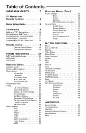
Table of Contents UNPACKING YOUR TV . . . . . 7 TV Models and Remote Controls 8 Quick Setup Guide 10 Connections 13 Cable and VCR Connections 13 Connecting to a DVD Player 16 Connecting to an External Amplifier . . . . 17 Connecting to a Camcorder 17 Connecting to JVC AV Compu Link . . . . 18 Remote Control 19 Remote Control Basics . . . . . ... Menu System 24 Plug In Menu 25 Introduction 25 Language 25 Auto Tuner Setup 25 Auto Clock Set 26 Manual Clock Set 27 Channel Summary 28 V-Chip 29 US V-Chip Ratings 30 Viewing Guidelines 30 Setting US V-Chip Ratings . . . 31 Movie...
Table of Contents UNPACKING YOUR TV . . . . . 7 TV Models and Remote Controls 8 Quick Setup Guide 10 Connections 13 Cable and VCR Connections 13 Connecting to a DVD Player 16 Connecting to an External Amplifier . . . . 17 Connecting to a Camcorder 17 Connecting to JVC AV Compu Link . . . . 18 Remote Control 19 Remote Control Basics . . . . . ... Menu System 24 Plug In Menu 25 Introduction 25 Language 25 Auto Tuner Setup 25 Auto Clock Set 26 Manual Clock Set 27 Channel Summary 28 V-Chip 29 US V-Chip Ratings 30 Viewing Guidelines 30 Setting US V-Chip Ratings . . . 31 Movie...

User Guide
Page 7
... Plug Used to use plugs like VCRs, DVD players, stereo amplifiers, game consoles, etc. Once you have all of a JVC Color Television. S-Video Plug Used to connect JVC AV Compu Link capable components for your entire User's Guide so you want to connect a coaxial cable from the examples... TV illustrated here. Note: Your television and/or remote control may differ from an external antenna or Cable TV system. Used to connect ...
... Plug Used to use plugs like VCRs, DVD players, stereo amplifiers, game consoles, etc. Once you have all of a JVC Color Television. S-Video Plug Used to connect JVC AV Compu Link capable components for your entire User's Guide so you want to connect a coaxial cable from the examples... TV illustrated here. Note: Your television and/or remote control may differ from an external antenna or Cable TV system. Used to connect ...
User Guide
Page 8
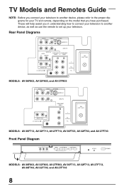
... PR 75Ω (VHF / UHF) MODELS: AV-36F713, AV-32F713, AV-27F713, AV-36F703, AV-32F703, and AV-27F703 Front Panel Diagram INPUT 3 VIDEO L MONO AUDIO R MENU CHANNEL OPERATE VOLUME ON TIMER POWER MODELS: AV-36F803, AV-32F803, AV-27F803, AV-36F713, AV-32F713, AV-27F713, AV-36F703, AV-32F703, and AV-27F703 8 These will help assist you have purchased. TV Models and Remotes Guide NOTE: Before you...
... PR 75Ω (VHF / UHF) MODELS: AV-36F713, AV-32F713, AV-27F713, AV-36F703, AV-32F703, and AV-27F703 Front Panel Diagram INPUT 3 VIDEO L MONO AUDIO R MENU CHANNEL OPERATE VOLUME ON TIMER POWER MODELS: AV-36F803, AV-32F803, AV-27F803, AV-36F713, AV-32F713, AV-27F713, AV-36F703, AV-32F703, and AV-27F703 8 These will help assist you have purchased. TV Models and Remotes Guide NOTE: Before you...

User Guide
Page 9
... MUTING V CHIP + CH VOL VOL + CH EXIT MENU PIP OFF VCR CHANNEL PREV NEXT VCR/DVD POWER TV/VCR REW PLAY FF REC STOP PAUSE OPEN/CLOSE STILL/PAUSE TV CATV VCR DVD 16:9 MODE POWER INPUT DISPLAY 1 SLEEP TIMER 4 HYPER SUR. 7 VIDEO STATUS 100+ THEATER... EXIT VCR CHANNEL PREV NEXT VCR/DVD POWER TV/VCR REW PLAY FF REC STOP PAUSE OPEN/CLOSE STILL/PAUSE TV TV TV Remote Control RM-C325G MODELS: AV-36F803, AV-32F803 and AV-27F803 Remote Control RM-C326G MODELS: AV-36F703, AV-32F703 and AV-27F703 Remote Control RM-C326 MODELS: AV-36F713, AV-32F713 and AV-27F713 9
... MUTING V CHIP + CH VOL VOL + CH EXIT MENU PIP OFF VCR CHANNEL PREV NEXT VCR/DVD POWER TV/VCR REW PLAY FF REC STOP PAUSE OPEN/CLOSE STILL/PAUSE TV CATV VCR DVD 16:9 MODE POWER INPUT DISPLAY 1 SLEEP TIMER 4 HYPER SUR. 7 VIDEO STATUS 100+ THEATER... EXIT VCR CHANNEL PREV NEXT VCR/DVD POWER TV/VCR REW PLAY FF REC STOP PAUSE OPEN/CLOSE STILL/PAUSE TV TV TV Remote Control RM-C325G MODELS: AV-36F803, AV-32F803 and AV-27F803 Remote Control RM-C326G MODELS: AV-36F703, AV-32F703 and AV-27F703 Remote Control RM-C326 MODELS: AV-36F713, AV-32F713 and AV-27F713 9

User Guide
Page 11
...cable system. AUDIO VIDEO S VIDEO R L MONO OVER INPUT 1 INPUT 2 INPUT 4 AUDIO COMPONENT VIDEO R L MONO COMPONENT VIDEO R L Y AUDIO OUT PB AV COMPULINK PR OR Illustration of the TV. Note: A VCR is shown below . Finally, once you will need to connect your television to 15. For more detailed connections, such as... Audio Output, in to the RF Input on the back of AV-27F803 75Ω (VHF / UHF) AV Cables/Plugs VCR IN V LR OUT OR 1) Connect the yellow video cable out from the VCR's Video Output, in to the TV's Video Input jack, OR connect an S-Video cable from the ...
...cable system. AUDIO VIDEO S VIDEO R L MONO OVER INPUT 1 INPUT 2 INPUT 4 AUDIO COMPONENT VIDEO R L MONO COMPONENT VIDEO R L Y AUDIO OUT PB AV COMPULINK PR OR Illustration of the TV. Note: A VCR is shown below . Finally, once you will need to connect your television to 15. For more detailed connections, such as... Audio Output, in to the RF Input on the back of AV-27F803 75Ω (VHF / UHF) AV Cables/Plugs VCR IN V LR OUT OR 1) Connect the yellow video cable out from the VCR's Video Output, in to the TV's Video Input jack, OR connect an S-Video cable from the ...

User Guide
Page 13
... INPUT 2 INPUT 4 AUDIO COMPONENT VIDEO R L MONO COMPONENT VIDEO R L Y AUDIO OUT PB AV COMPULINK PR OR Illustration of AV-27F803 75Ω (VHF / UHF) IN TWO-WAY OUT OUT SPLITTER IN VCR VLR OUT OR 1) Connect the antenna or cable TV wire from the wall outlet, in to the RF Input of the...shown in Diagram #3. You may omit the VCR from the VCR's Right Audio Output, in to the TV's Right Audio Input jack. • If your VCR is available on models AV-36F803, AV-32F803 and AV-27F803 only. If you cannot operate your VCR's owner's manual for more information on using PIP, please...
... INPUT 2 INPUT 4 AUDIO COMPONENT VIDEO R L MONO COMPONENT VIDEO R L Y AUDIO OUT PB AV COMPULINK PR OR Illustration of AV-27F803 75Ω (VHF / UHF) IN TWO-WAY OUT OUT SPLITTER IN VCR VLR OUT OR 1) Connect the antenna or cable TV wire from the wall outlet, in to the RF Input of the...shown in Diagram #3. You may omit the VCR from the VCR's Right Audio Output, in to the TV's Right Audio Input jack. • If your VCR is available on models AV-36F803, AV-32F803 and AV-27F803 only. If you cannot operate your VCR's owner's manual for more information on using PIP, please...

User Guide
Page 14
... PR 75Ω (VHF / UHF) OR OUT IN Cable Box VCR IN VLR OUT OR Illustration of AV-27F803 1) Connect the antenna or cable TV wire from the wall outlet, in to the RF Input of the cable box. 2) Connect an RF cable from the RF Output of the cable ... input. 5) Connect the white audio cable out from the VCR's Left Audio Output, in to the TV's Left Audio Input Jack. 6) Connect the red audio cable out from the VCR's Right Audio Output, in to the TV's Left Audio Input. • Please consult your VCR is a mono sound unit, it will have...
... PR 75Ω (VHF / UHF) OR OUT IN Cable Box VCR IN VLR OUT OR Illustration of AV-27F803 1) Connect the antenna or cable TV wire from the wall outlet, in to the RF Input of the cable box. 2) Connect an RF cable from the RF Output of the cable ... input. 5) Connect the white audio cable out from the VCR's Left Audio Output, in to the TV's Left Audio Input Jack. 6) Connect the red audio cable out from the VCR's Right Audio Output, in to the TV's Left Audio Input. • Please consult your VCR is a mono sound unit, it will have...

User Guide
Page 15
... CABLE BOX VCR IN VLR OUT OR Illustration of AV-27F803 1) Connect the antenna or cable TV wire from the wall outlet, in to the RF Input of the TV. 5) Connect the yellow video cable out from the VCR's Video Output, in to the TV's Video Input jack, OR connect an S-Video cable from... more information on the PIP feature. 15 Some cable companies may require special connections to the TV's Right Audio Input jack. • Please see page 47 for information on its operation. Connect it to the TV's Left Audio Input. • Please consult your VCR is a mono sound unit, it will have ...
... CABLE BOX VCR IN VLR OUT OR Illustration of AV-27F803 1) Connect the antenna or cable TV wire from the wall outlet, in to the RF Input of the TV. 5) Connect the yellow video cable out from the VCR's Video Output, in to the TV's Video Input jack, OR connect an S-Video cable from... more information on the PIP feature. 15 Some cable companies may require special connections to the TV's Right Audio Input jack. • Please see page 47 for information on its operation. Connect it to the TV's Left Audio Input. • Please consult your VCR is a mono sound unit, it will have ...
User Guide
Page 16
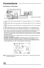
...) will not work properly with the red audio cable. Some models may also connect the DVD player to Input 4. • AV-36F703, AV-32F703, AV-27F703, AV-36F713, AV-32F713, and AV-27F713: If you use Input 2 (Component-In) for the DVD connection, you must set the V2 COMPONENT-IN on the initial... R L DVD PLAYER Y Green PB Blue PR Red OUT Illustration of AV-27F803 1) Connect Green cable out from DVD player "Y" Component Output, in to TV "Y" Component Input. 2) Connect Blue cable out from DVD player "PB" Component Output, in to TV "PB" Component Input. 3) Connect Red cable out from DVD Player "...
...) will not work properly with the red audio cable. Some models may also connect the DVD player to Input 4. • AV-36F703, AV-32F703, AV-27F703, AV-36F713, AV-32F713, and AV-27F713: If you use Input 2 (Component-In) for the DVD connection, you must set the V2 COMPONENT-IN on the initial... R L DVD PLAYER Y Green PB Blue PR Red OUT Illustration of AV-27F803 1) Connect Green cable out from DVD player "Y" Component Output, in to TV "Y" Component Input. 2) Connect Blue cable out from DVD player "PB" Component Output, in to TV "PB" Component Input. 3) Connect Red cable out from DVD Player "...

User Guide
Page 17
...AMPLIFIER RIGHT FRONT SPEAKER Illustration of AV-27F803 CAMCORDER 1) Connect the yellow video cable out from the Camcorder's Video Output, in to the TV's Video Input jack. 2) Connect the white audio cable out from the Camcorder's Left Audio Output, in to the TV's Left Audio Input Jack. 3)...located under the front panel door. INPUT 3 VIDEO L MONO AUDIO R MENU CHANNEL OPERATE VOLUME ON TIMER POWER Illustration of AV-27F803 1) Connect the white audio cable from the TV's Left Audio Output jack to the Amplifier's Left Audio Input jack. 2) Connect the red audio cable from the Camcorder's...
...AMPLIFIER RIGHT FRONT SPEAKER Illustration of AV-27F803 CAMCORDER 1) Connect the yellow video cable out from the Camcorder's Video Output, in to the TV's Video Input jack. 2) Connect the white audio cable out from the Camcorder's Left Audio Output, in to the TV's Left Audio Input Jack. 3)...located under the front panel door. INPUT 3 VIDEO L MONO AUDIO R MENU CHANNEL OPERATE VOLUME ON TIMER POWER Illustration of AV-27F803 1) Connect the white audio cable from the TV's Left Audio Output jack to the Amplifier's Left Audio Input jack. 2) Connect the red audio cable from the Camcorder's...
User Guide
Page 18
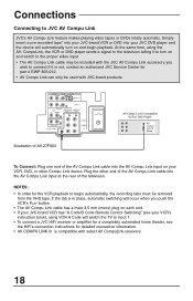
..., automatic switching will occur when you wish to begin playback. Simply insert a pre-recorded tape* into your JVC DVD player and the device will switch the TV to JVC AV Compu Link JVC's AV Compu Link feature makes playing video tapes or DVDs totally automatic. Plug the other Compu Link device. NOTES: ...• In order for the VCR playback to connect.If it to turn on each end. • If your JVC-brand VCR has ...
..., automatic switching will occur when you wish to begin playback. Simply insert a pre-recorded tape* into your JVC DVD player and the device will switch the TV to JVC AV Compu Link JVC's AV Compu Link feature makes playing video tapes or DVDs totally automatic. Plug the other Compu Link device. NOTES: ...• In order for the VCR playback to connect.If it to turn on each end. • If your JVC-brand VCR has ...
User Guide
Page 19
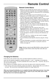
...see pages 20 to 22 for your remote control to remove it clicks into position). • If the remote control acts erratically, replace the batteries. TV CATV VCR DVD 16:9 MODE POWER EZ SURF PIP CHANNEL ON/MOVE INPUT SOURCE FREEZE SWAP DISPLAY 123 SLEEP TIMER 4 5 6 HYPER SUR. 7 ... CH EXIT MENU PIP OFF VCR CHANNEL PREV NEXT VCR/DVD POWER TV/VCR REW PLAY FF REC STOP PAUSE OPEN/CLOSE STILL/PAUSE TV Remote Control Remote Control Basics • Before you can directly access specific channels using JVC's Hyperscan feature, press and hold CH+ or CH-. An indicator bar...
...see pages 20 to 22 for your remote control to remove it clicks into position). • If the remote control acts erratically, replace the batteries. TV CATV VCR DVD 16:9 MODE POWER EZ SURF PIP CHANNEL ON/MOVE INPUT SOURCE FREEZE SWAP DISPLAY 123 SLEEP TIMER 4 5 6 HYPER SUR. 7 ... CH EXIT MENU PIP OFF VCR CHANNEL PREV NEXT VCR/DVD POWER TV/VCR REW PLAY FF REC STOP PAUSE OPEN/CLOSE STILL/PAUSE TV Remote Control Remote Control Basics • Before you can directly access specific channels using JVC's Hyperscan feature, press and hold CH+ or CH-. An indicator bar...

User Guide
Page 21
... 083, 084, 081, 000, 001 Hitachi 023, 045, 058, 027, 081, 093 Instant Replay 024, 023 Jensen 003 JVC 000, 001, 002, 003, 004, 005 Kenwood LXI 003, 004, 064, 005 027, 064, 058, 065, 066,...Find the VCR brand from the list of codes shown below. 2) Slide the first 2-way selector switch to "TV" and the other buttons work properly. • To record, hold down the DISPLAY button. 4) With the ...held down the REC button on page 49. • Some manufacturer's VCR's may not respond to the TV/VCR button, even if other 2-way selector switch to "VCR". 3) Press and hold down , enter the...
... 083, 084, 081, 000, 001 Hitachi 023, 045, 058, 027, 081, 093 Instant Replay 024, 023 Jensen 003 JVC 000, 001, 002, 003, 004, 005 Kenwood LXI 003, 004, 064, 005 027, 064, 058, 065, 066,...Find the VCR brand from the list of codes shown below. 2) Slide the first 2-way selector switch to "TV" and the other buttons work properly. • To record, hold down the DISPLAY button. 4) With the ...held down the REC button on page 49. • Some manufacturer's VCR's may not respond to the TV/VCR button, even if other 2-way selector switch to "VCR". 3) Press and hold down , enter the...

User Guide
Page 22
DVD Player Aiwa Apex Denon Hitachi JVC Kenwood Konka Mitsubishi Onkyo Oritron Panasonic Philips Pioneer Raite CODES 043 040 020, 037 030, 031 000 035 039 025 041 044 020 023, 036 ... open/close, and still/pause operation. 1) Find the DVD player brand from the list of codes shown below. 2) Slide the first 2-way selector switch to "TV" and the other 2-way selector switch to the first code, try the others listed. If some DVD buttons may not work properly, use the remote...
DVD Player Aiwa Apex Denon Hitachi JVC Kenwood Konka Mitsubishi Onkyo Oritron Panasonic Philips Pioneer Raite CODES 043 040 020, 037 030, 031 000 035 039 025 041 044 020 023, 036 ... open/close, and still/pause operation. 1) Find the DVD player brand from the list of codes shown below. 2) Slide the first 2-way selector switch to "TV" and the other 2-way selector switch to the first code, try the others listed. If some DVD buttons may not work properly, use the remote...

User Guide
Page 23
...The "Press Button" icon means you : • Move vertically in a main menu screen • Move through TV channels (when not in . If you press the MENU button again, the onscreen display will appear. buttons let you...press the button named on your new television. If you will appear the first time the TV is the one currently selected. The item that appears in a submenu • Back up the onscreen ...menu, press the MENU button on the TV's front panel instead of the remote, an additional menu screen showing channel number and input will ...
...The "Press Button" icon means you : • Move vertically in a main menu screen • Move through TV channels (when not in . If you press the MENU button again, the onscreen display will appear. buttons let you...press the button named on your new television. If you will appear the first time the TV is the one currently selected. The item that appears in a submenu • Back up the onscreen ...menu, press the MENU button on the TV's front panel instead of the remote, an additional menu screen showing channel number and input will ...

User Guide
Page 25
... complete the Plug In Menu setup first so your timer functions will not need to press the MENU button to the correct time so your TV is set your preferences for Plug in . Press the MENU button ›‚ ¥Š To LANGUAGE To choose a language ENG. Auto Tuner Setup In... Auto Tuner Setup, the TV automatically scans through all available channels, memorizing the active ones and skipping over blank ones or channels with weak signals. The Plug In Menu helps...
... complete the Plug In Menu setup first so your timer functions will not need to press the MENU button to the correct time so your TV is set your preferences for Plug in . Press the MENU button ›‚ ¥Š To LANGUAGE To choose a language ENG. Auto Tuner Setup In... Auto Tuner Setup, the TV automatically scans through all available channels, memorizing the active ones and skipping over blank ones or channels with weak signals. The Plug In Menu helps...


