Owners Manual
Page 3
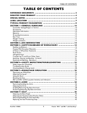
...Recline Only 41 Removing/Installing the Seat Assembly 42 Replacing the Seat Positioning Strap ...43 Part No 1125085 3 Pronto® M51™and M61™with SureStep® TABLE OF CONTENTS TABLE OF CONTENTS REFERENCE DOCUMENTS 2 REGISTER YOUR PRODUCT 4 SPECIAL ...LOCATION 7 TYPICAL PRODUCT PARAMETERS 8 SECTION 1-GENERAL GUIDELINES 10 Controller Settings/Repair or Service 10 Accessories ...10 Operation Information ...10 Batteries...12 Grounding Instructions ...13 Rain Test...13 Weight Training ...13 Weight Limitation...13 SECTION 2-EMI INFORMATION 14 SECTION 3-SAFETY/HANDLING OF...
...Recline Only 41 Removing/Installing the Seat Assembly 42 Replacing the Seat Positioning Strap ...43 Part No 1125085 3 Pronto® M51™and M61™with SureStep® TABLE OF CONTENTS TABLE OF CONTENTS REFERENCE DOCUMENTS 2 REGISTER YOUR PRODUCT 4 SPECIAL ...LOCATION 7 TYPICAL PRODUCT PARAMETERS 8 SECTION 1-GENERAL GUIDELINES 10 Controller Settings/Repair or Service 10 Accessories ...10 Operation Information ...10 Batteries...12 Grounding Instructions ...13 Rain Test...13 Weight Training ...13 Weight Limitation...13 SECTION 2-EMI INFORMATION 14 SECTION 3-SAFETY/HANDLING OF...

Owners Manual
Page 4
...Safeguarding your registration. Any registration information you submit will only be used by Invacare Corporation and protected as required by applicable laws and regulations. Pronto® M51™and M61™with product information, maintenance tips and industry news. ... 58 Adjusting Forks ...59 SECTION 11-BATTERIES 60 Warnings For Handling and Replacing Batteries 60 Using the Proper Batteries...61 Removing/Installing Batteries from/into Battery Tray 61 Connecting/Disconnecting Battery Cables 63 Charging Batteries ...66 Battery Charger Operation...67 SECTION 12-ELECTRONICS 71...
...Safeguarding your registration. Any registration information you submit will only be used by Invacare Corporation and protected as required by applicable laws and regulations. Pronto® M51™and M61™with product information, maintenance tips and industry news. ... 58 Adjusting Forks ...59 SECTION 11-BATTERIES 60 Warnings For Handling and Replacing Batteries 60 Using the Proper Batteries...61 Removing/Installing Batteries from/into Battery Tray 61 Connecting/Disconnecting Battery Cables 63 Charging Batteries ...66 Battery Charger Operation...67 SECTION 12-ELECTRONICS 71...
Owners Manual
Page 8
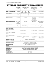
... in 5° increments Charcoal Grey Vinyl Black Nylon Back with Seat Pan SEAT-TO-FLOOR WITH FOOTBOARD (M51): 20 to 24 inches 19 to 23 inches 17 to 21 inches WITH FRONT RIGGINGS (M51): 22 to 24 inches 19 to 23 inches 19 to 21 inches WITH ELEVATING SEAT (M61): OVERALL WIDTH...: OVERALL HEIGHT: OVERALL LENGTH: DRIVE WHEELS/ TIRES: CASTER: FOOTRESTS/ LEGRESTS: *WEIGHT W/O BATTERIES: W/BATTERIES (U1): 21 to 23 inches + up to 5 inches of ...
... in 5° increments Charcoal Grey Vinyl Black Nylon Back with Seat Pan SEAT-TO-FLOOR WITH FOOTBOARD (M51): 20 to 24 inches 19 to 23 inches 17 to 21 inches WITH FRONT RIGGINGS (M51): 22 to 24 inches 19 to 23 inches 19 to 21 inches WITH ELEVATING SEAT (M61): OVERALL WIDTH...: OVERALL HEIGHT: OVERALL LENGTH: DRIVE WHEELS/ TIRES: CASTER: FOOTRESTS/ LEGRESTS: *WEIGHT W/O BATTERIES: W/BATTERIES (U1): 21 to 23 inches + up to 5 inches of ...
Owners Manual
Page 9
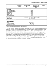
Users should become familiar with SureStep® Part No 1125085 9 Pronto® M51™and M61™with the battery discharge indicator on the joystick to Battery Charger Operation on certain ideal conditions. Refer to determine the range of their individual ...results. While considered typical, they are calculated for maximum chair weight rating using largest batteries applicable (U1), per test procedures described in actual values for this product. Quantity 2 300 lbs PERFORMANCE SPEED: TURNING RADIUS: **RANGE...
Users should become familiar with SureStep® Part No 1125085 9 Pronto® M51™and M61™with the battery discharge indicator on the joystick to Battery Charger Operation on certain ideal conditions. Refer to determine the range of their individual ...results. While considered typical, they are calculated for maximum chair weight rating using largest batteries applicable (U1), per test procedures described in actual values for this product. Quantity 2 300 lbs PERFORMANCE SPEED: TURNING RADIUS: **RANGE...
Owners Manual
Page 12
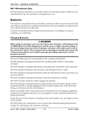
...be used. Read and carefully follow the manufacturer's instructions for proper procedures. DO NOT under any type of fire and electric shock. Invacare strongly recommends their use only a three wire extension cord having at least 16 AWG (American Wire Gauge) wire and the same ...cycle gel cell or sealed lead acid batteries. SECTION 1-GENERAL GUIDELINES M61 Wheelchairs Only DO NOT operate wheelchair on ‐board battery charger and an independent battery charger (plugged into the joystick charger port) at the same time. Pronto® M51™and M61™with SureStep®...
...be used. Read and carefully follow the manufacturer's instructions for proper procedures. DO NOT under any type of fire and electric shock. Invacare strongly recommends their use only a three wire extension cord having at least 16 AWG (American Wire Gauge) wire and the same ...cycle gel cell or sealed lead acid batteries. SECTION 1-GENERAL GUIDELINES M61 Wheelchairs Only DO NOT operate wheelchair on ‐board battery charger and an independent battery charger (plugged into the joystick charger port) at the same time. Pronto® M51™and M61™with SureStep®...
Owners Manual
Page 13
...Check to prematurely rust or may damage the upholstery. Part No 1125085 13 Pronto® M51™and M61™with or for an extended period of its power wheelchairs in a damp area for Invacare products. DO NOT store power wheelchair in accordance with three‐prong (grounding) plugs for...excessive rain or dampness may cause the chair to malfunction electrically and mechanically, may cause the chair to ensure that the RED and GREY battery terminal caps are secured in a rain storm of any kind of the customer to remove his/her power wheelchair from any plug used ...
...Check to prematurely rust or may damage the upholstery. Part No 1125085 13 Pronto® M51™and M61™with or for an extended period of its power wheelchairs in a damp area for Invacare products. DO NOT store power wheelchair in accordance with three‐prong (grounding) plugs for...excessive rain or dampness may cause the chair to malfunction electrically and mechanically, may cause the chair to ensure that the RED and GREY battery terminal caps are secured in a rain storm of any kind of the customer to remove his/her power wheelchair from any plug used ...
Owners Manual
Page 19
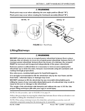
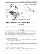
... independently of a wheelchair may occur when rotating the footboard assembly (Detail "B"). Part No 1125085 19 Pronto® M51™and M61™with batteries and without the user is necessary to the wheelchair. otherwise injury or damage may occur when adjusting the arm angle... position (Detail "A"). Extreme caution is advised when it is 212 lbs. Invacare recommends using a stairway. SECTION 3-SAFETY/HANDLING OF...
... independently of a wheelchair may occur when rotating the footboard assembly (Detail "B"). Part No 1125085 19 Pronto® M51™and M61™with batteries and without the user is necessary to the wheelchair. otherwise injury or damage may occur when adjusting the arm angle... position (Detail "A"). Extreme caution is advised when it is 212 lbs. Invacare recommends using a stairway. SECTION 3-SAFETY/HANDLING OF...
Owners Manual
Page 25
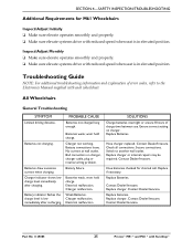
... drive with SureStep® Contact Dealer/Invacare. Batteries draw excessive current when charging. Replace batteries. PROBABLE CAUSE Batteries not charged long enough. Check all connections. All Wheelchairs General Troubleshooting SYMPTOM Limited driving distance. Batteries weak, wont hold charge. Replace Batteries. Contact Dealer/Invacare. Secure connections. Part No 1125085 25 Pronto® M51™and M61™with reduced...
... drive with SureStep® Contact Dealer/Invacare. Batteries draw excessive current when charging. Replace batteries. PROBABLE CAUSE Batteries not charged long enough. Check all connections. All Wheelchairs General Troubleshooting SYMPTOM Limited driving distance. Batteries weak, wont hold charge. Replace Batteries. Contact Dealer/Invacare. Secure connections. Part No 1125085 25 Pronto® M51™and M61™with reduced...
Owners Manual
Page 26
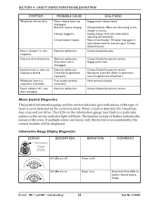
...again, it may indicate need for service. Contact Dealer/Invacare for service. Information Gauge Display Diagnostics DISPLAY Information Gauge Display DESCRIPTION DEFINITION COMMENTS All LEDs are disengaged. Pronto® M51™and M61™with wheelchair). Joystick erratic or...disengaged. Controller programmed improperly. The LEDs on implies reduced battery charge. Contact Dealer/Invacare. All LEDs are found, only the first error encountered by the control module. Electrical malfunction. Batteries require charging. Electrical malfunction. Fewer than three LEDs ...
...again, it may indicate need for service. Contact Dealer/Invacare for service. Information Gauge Display Diagnostics DISPLAY Information Gauge Display DESCRIPTION DEFINITION COMMENTS All LEDs are disengaged. Pronto® M51™and M61™with wheelchair). Joystick erratic or...disengaged. Controller programmed improperly. The LEDs on implies reduced battery charge. Contact Dealer/Invacare. All LEDs are found, only the first error encountered by the control module. Electrical malfunction. Batteries require charging. Electrical malfunction. Fewer than three LEDs ...
Owners Manual
Page 27
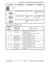
...of-Neutral-at-Power-Up to Right "chase" alter- Contact Invacare/Dealer for service. Contact Invacare/Dealer for service. Wrong type of the ing mode. Battery charge is flashing. Contact Invacare/Dealer for service. SECTION 4-SAFETY INSPECTION/TROUBLESHOOTING DISPLAY Information Gauge... and try again. Part No 1125085 27 Pronto® M51™and M61™with steady display. Charge the batteries. Joystick has detected Out- Contact Invacare/Dealer for service. Contact Invacare/Dealer for service. The steady LEDs indicate nating with SureStep...
...of-Neutral-at-Power-Up to Right "chase" alter- Contact Invacare/Dealer for service. Contact Invacare/Dealer for service. Wrong type of the ing mode. Battery charge is flashing. Contact Invacare/Dealer for service. SECTION 4-SAFETY INSPECTION/TROUBLESHOOTING DISPLAY Information Gauge... and try again. Part No 1125085 27 Pronto® M51™and M61™with steady display. Charge the batteries. Joystick has detected Out- Contact Invacare/Dealer for service. Contact Invacare/Dealer for service. The steady LEDs indicate nating with SureStep...
Owners Manual
Page 28
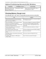
... maintenance of batteries in this manual when selecting a battery or charger. Pronto® M51™and M61™with tools. Checking Battery Charge Level The following "Do's" and "Don'ts" are provided for a GEL battery or "Sealed" battery. Follow recommendations in an area that accompanies a battery and charger before opening battery box or installing service batteries. Push battery clamps on...
... maintenance of batteries in this manual when selecting a battery or charger. Pronto® M51™and M61™with tools. Checking Battery Charge Level The following "Do's" and "Don'ts" are provided for a GEL battery or "Sealed" battery. Follow recommendations in an area that accompanies a battery and charger before opening battery box or installing service batteries. Push battery clamps on...
Owners Manual
Page 35
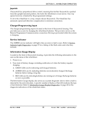
... taking a long trip. Refer to Information Gauge Display Diagnostics on page 27 for charging the wheelchair batteries. C. Part No 1125085 35 Pronto® M51™and M61™with SureStep® Service Indicator The AMBER service indicator will light when an error or ...fault occurs. GREEN LEDs are moderately charged. B. True state‐of‐battery‐charge, including notification of the joystick housing....
... taking a long trip. Refer to Information Gauge Display Diagnostics on page 27 for charging the wheelchair batteries. C. Part No 1125085 35 Pronto® M51™and M61™with SureStep® Service Indicator The AMBER service indicator will light when an error or ...fault occurs. GREEN LEDs are moderately charged. B. True state‐of‐battery‐charge, including notification of the joystick housing....
Owners Manual
Page 57
... disengagement/engagement allows freewheeling or joystick controlled operation. M61 TOP SHROUD Clip Hook and Loop Strap Front Shroud NOTE: Batteries not shown for pushing, if necessary. Part No 1125085 57 Pronto® M51™and M61™with SureStep® NOTE: It may be necessary to rock the wheels slightly until the...
... disengagement/engagement allows freewheeling or joystick controlled operation. M61 TOP SHROUD Clip Hook and Loop Strap Front Shroud NOTE: Batteries not shown for pushing, if necessary. Part No 1125085 57 Pronto® M51™and M61™with SureStep® NOTE: It may be necessary to rock the wheels slightly until the...
Owners Manual
Page 60
...repair or service and before performing this section. Wheelchairs that are frequently exposed to avoid contact with batteries. Invacare strongly recommends that battery installation and battery replacement ALWAYS be examined during maintenance for signs of corrosion (water exposure, incontinence, etc.). Electrical...serious personal injury or damage may result. NEVER install/reinstall a battery with fuse. Failure to use a battery handle/lifting strap when lifting a battery. DO NOT tip the batteries. Pronto® M51™and M61™with your legs) to BLACK). It also...
...repair or service and before performing this section. Wheelchairs that are frequently exposed to avoid contact with batteries. Invacare strongly recommends that battery installation and battery replacement ALWAYS be examined during maintenance for signs of corrosion (water exposure, incontinence, etc.). Electrical...serious personal injury or damage may result. NEVER install/reinstall a battery with fuse. Failure to use a battery handle/lifting strap when lifting a battery. DO NOT tip the batteries. Pronto® M51™and M61™with your legs) to BLACK). It also...

Owners Manual
Page 61
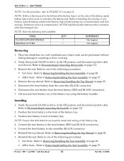
...FIGURE 11.1. 1. DO NOT tip the batteries. Keep the batteries in an upright position. Part No 1125085 61 Pronto® M51™and M61™with terminal configuration as shown below MUST be used . SECTION 11-BATTERIES Using the Proper Batteries NOTE: For this procedure, refer to... prolong the life of battery (FIGURE 11.1). 3. Visually draw a horizontal ...
...FIGURE 11.1. 1. DO NOT tip the batteries. Keep the batteries in an upright position. Part No 1125085 61 Pronto® M51™and M61™with terminal configuration as shown below MUST be used . SECTION 11-BATTERIES Using the Proper Batteries NOTE: For this procedure, refer to... prolong the life of battery (FIGURE 11.1). 3. Visually draw a horizontal ...
Owners Manual
Page 62
...® 62 Part No 1125085 Refer to one of the battery, apply baking soda to these areas to carpeting or floor covering. 2. Disconnect the front battery from the front battery (RED and BLACK connectors). 7. Disconnect the rear battery from the controller (BLACK connector). 6. Pronto® M51™and M61™with a cracked or otherwise damaged...
...® 62 Part No 1125085 Refer to one of the battery, apply baking soda to these areas to carpeting or floor covering. 2. Disconnect the front battery from the front battery (RED and BLACK connectors). 7. Disconnect the rear battery from the controller (BLACK connector). 6. Pronto® M51™and M61™with a cracked or otherwise damaged...
Owners Manual
Page 63
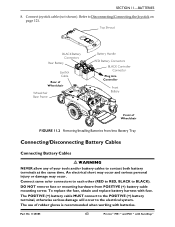
... use of Wheelchair FIGURE 11.2 Removing/Installing Batteries from POSITIVE (+) battery cable mounting screw. An electrical short may occur and serious personal injury or damage may occur. Part No 1125085 63 Pronto® M51™and M61™with batteries. To replace the fuse, obtain and replace battery harness with fuse. Connect joystick cable (not...
... use of Wheelchair FIGURE 11.2 Removing/Installing Batteries from POSITIVE (+) battery cable mounting screw. An electrical short may occur and serious personal injury or damage may occur. Part No 1125085 63 Pronto® M51™and M61™with batteries. To replace the fuse, obtain and replace battery harness with fuse. Connect joystick cable (not...
Owners Manual
Page 64
...with a tie‐wrap [use . Position the batteries into Battery Tray on page 61. Refer to FIGURE 11.3 on battery type), otherwise damage to use tie‐wraps 11‐1/2‐inches long] (Detail "B" of FIGURE 11.3). 5. Pronto® M51™and M61™with mounting screw and the ...locknut. 2. All battery terminal covers (two on the front battery and two on the rear battery) MUST be fully charged before using, otherwise the life of FIGURE 11.3 ...
...with a tie‐wrap [use . Position the batteries into Battery Tray on page 61. Refer to FIGURE 11.3 on battery type), otherwise damage to use tie‐wraps 11‐1/2‐inches long] (Detail "B" of FIGURE 11.3). 5. Pronto® M51™and M61™with mounting screw and the ...locknut. 2. All battery terminal covers (two on the front battery and two on the rear battery) MUST be fully charged before using, otherwise the life of FIGURE 11.3 ...

Owners Manual
Page 65
... 1125085 65 Pronto® M51™and M61™with Mounting Screw POSITIVE (+) Battery terminal NOTE: Handles on batteries removed for clarity. Mounting Screw NEGATIVE (-) Battery Cable NEGATIVE (-) Battery terminal L-Bracket with SureStep® SECTION 11-BATTERIES POSITIVE (+) Battery Terminal Cap NEGATIVE (-) Battery Terminal Cap BLACK Connectors POSITIVE (+) Battery Cable DETAIL "A" RED Connectors NOTE: Battery terminal caps not shown on...
... 1125085 65 Pronto® M51™and M61™with Mounting Screw POSITIVE (+) Battery terminal NOTE: Handles on batteries removed for clarity. Mounting Screw NEGATIVE (-) Battery Cable NEGATIVE (-) Battery terminal L-Bracket with SureStep® SECTION 11-BATTERIES POSITIVE (+) Battery Terminal Cap NEGATIVE (-) Battery Terminal Cap BLACK Connectors POSITIVE (+) Battery Cable DETAIL "A" RED Connectors NOTE: Battery terminal caps not shown on...
Owners Manual
Page 66
... FIGURE 11.3). 4. Cut the tie‐wrap that secures the battery terminal cap in the wheelchair while recharging the batteries. Disconnect POSITIVE (+) battery cable from NEGATIVE (‐) battery terminal (FIGURE 11.3). Pronto® M51™and M61™with batteries. Disconnect NEGATIVE (‐) battery cable from the POSITIVE (+) battery terminal (FIGURE 11.3). 6. DO NOT attempt to Removing/Installing...
... FIGURE 11.3). 4. Cut the tie‐wrap that secures the battery terminal cap in the wheelchair while recharging the batteries. Disconnect POSITIVE (+) battery cable from NEGATIVE (‐) battery terminal (FIGURE 11.3). Pronto® M51™and M61™with batteries. Disconnect NEGATIVE (‐) battery cable from the POSITIVE (+) battery terminal (FIGURE 11.3). 6. DO NOT attempt to Removing/Installing...


