
User Guide
Page 3
... their locations. Use this server board. In this Manual Thank you for Intel products, see http://support.intel.com/support/motherboards/server/SE7520JR2/compat.htm. Preface About this chapter, you will find BIOS error messages and POST code messages. Product Accessories This server board is written for system technicians who are shipped with your server: Processor, memory DIMMs, hard drive, floppy...
... their locations. Use this server board. In this Manual Thank you for Intel products, see http://support.intel.com/support/motherboards/server/SE7520JR2/compat.htm. Preface About this chapter, you will find BIOS error messages and POST code messages. Product Accessories This server board is written for system technicians who are shipped with your server: Processor, memory DIMMs, hard drive, floppy...

User Guide
Page 4
...software name in the search field at http://support.intel.com/support/motherboards/server/SE7520JR2 Accessories or other Intel server products Spares and Configuration Guide Hardware (peripheral boards, adapter cards) and operating systems that have ...Memory List To make sure your system falls within the allowed power budget For software to search "This Product." For this information or software For in-depth technical information about this product, including BIOS settings and chipset information If you need to install it Use this Document or Software Intel® Server Board SE7520JR2...
...software name in the search field at http://support.intel.com/support/motherboards/server/SE7520JR2 Accessories or other Intel server products Spares and Configuration Guide Hardware (peripheral boards, adapter cards) and operating systems that have ...Memory List To make sure your system falls within the allowed power budget For software to search "This Product." For this information or software For in-depth technical information about this product, including BIOS settings and chipset information If you need to install it Use this Document or Software Intel® Server Board SE7520JR2...
User Guide
Page 11
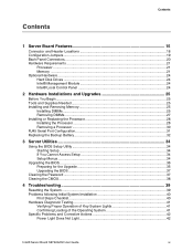
Contents Contents 1 Server Board Features 15 Connector and Header Locations 18 Configuration Jumpers ...19 Back Panel Connectors...20 Hardware Requirements ...21 Processor ...21 Memory ...21 Optional Hardware ...24 Hard Disk Drives ...24 Intel® Management Module 24 Intel® Local Control Panel 24 2 Hardware Installations and Upgrades 25 Before You Begin ...25 Tools and Supplies... of Key System Lights 41 Confirming Loading of the Operating System 41 Specific Problems and Corrective Actions 42 Power Light Does Not Light 42 Intel® Server Board SE7520JR2 User Guide xi
Contents Contents 1 Server Board Features 15 Connector and Header Locations 18 Configuration Jumpers ...19 Back Panel Connectors...20 Hardware Requirements ...21 Processor ...21 Memory ...21 Optional Hardware ...24 Hard Disk Drives ...24 Intel® Management Module 24 Intel® Local Control Panel 24 2 Hardware Installations and Upgrades 25 Before You Begin ...25 Tools and Supplies... of Key System Lights 41 Confirming Loading of the Operating System 41 Specific Problems and Corrective Actions 42 Power Light Does Not Light 42 Intel® Server Board SE7520JR2 User Guide xi
User Guide
Page 13
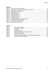
......20 Processor Support 21 DIMM Module Memory Capacity Support 22 Keyboard Commands 35 POST Error Beep Codes 49 Error Beep Codes Provided by Intel® Management Modules 49 Product Certification Markings 52 Intel® Server Board SE7520JR2 User Guide xiii Changing the Serial Port Configuration 31 Figure 11. Table 4. Intel® Server Board SE7520JR2 15 Figure 2. Configuration Jumper Location 19...
......20 Processor Support 21 DIMM Module Memory Capacity Support 22 Keyboard Commands 35 POST Error Beep Codes 49 Error Beep Codes Provided by Intel® Management Modules 49 Product Certification Markings 52 Intel® Server Board SE7520JR2 User Guide xiii Changing the Serial Port Configuration 31 Figure 11. Table 4. Intel® Server Board SE7520JR2 15 Figure 2. Configuration Jumper Location 19...

User Guide
Page 16
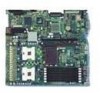
... and mouse RJ45 Serial B port Two RJ45 NIC connectors for up to two Intel® Xeon™ processors with an 800 MT/s MHz front side bus and frequencies starting at 2.8 GHz. Capable of the server board. Server Board Features Feature Description Processors Memory Chipset Support for 10/100/1000 Mb connections Two USB 2.0 ports U320 high...
... and mouse RJ45 Serial B port Two RJ45 NIC connectors for up to two Intel® Xeon™ processors with an 800 MT/s MHz front side bus and frequencies starting at 2.8 GHz. Capable of the server board. Server Board Features Feature Description Processors Memory Chipset Support for 10/100/1000 Mb connections Two USB 2.0 ports U320 high...
User Guide
Page 21
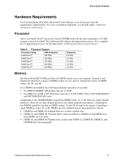
... Processor Family FSB Frequency Intel® Xeon™ 800 MHz Intel® Xeon™ 800 MHz Intel® Xeon™ 800 MHz Intel® Xeon™ 800 MHz Intel® Xeon™ 800 MHz Frequency 2.8 GHz 3.0 GHz 3.2 GHz 3.4 GHz 3.6 GHz Memory The Server Board SE7520JR2 provides six DIMM sockets across two channels, Channel A and Channel B. Intel® Server Board SE7520JR2 User Guide 21...
... Processor Family FSB Frequency Intel® Xeon™ 800 MHz Intel® Xeon™ 800 MHz Intel® Xeon™ 800 MHz Intel® Xeon™ 800 MHz Intel® Xeon™ 800 MHz Frequency 2.8 GHz 3.0 GHz 3.2 GHz 3.4 GHz 3.6 GHz Memory The Server Board SE7520JR2 provides six DIMM sockets across two channels, Channel A and Channel B. Intel® Server Board SE7520JR2 User Guide 21...

User Guide
Page 22
... only 240pin DIMMs on -line sparing provide a way to the Intel® Server Board SE7520JR2 Technical Product Specification for mirroring. 22 The system will be treated as DDR266. ƒ Use only DIMMs with a minimum of the installed DIMMs are used for additional information regarding the memory sub-system. DDR333, or DDR2-400 ECC, registered DDR...
... only 240pin DIMMs on -line sparing provide a way to the Intel® Server Board SE7520JR2 Technical Product Specification for mirroring. 22 The system will be treated as DDR266. ƒ Use only DIMMs with a minimum of the installed DIMMs are used for additional information regarding the memory sub-system. DDR333, or DDR2-400 ECC, registered DDR...
User Guide
Page 23
...the spare DIMMs must be equal to the Intel® Server Board SE7520JR2 Technical Product Specification for additional information regarding the memory sub-system. Only one DIMM per channel is used as the memory spare. Power Supply A minimum of 5 V standby current or the board will not boot. Your supply must be ...the spare DIMM in that use , but is not available for use DDR2 memory (SE7520JR2SCSID2 and SE7520JR2SATAD2): Four DIMMs are used in DIMM sockets 1A, 1B, 2A, and 2B. Intel® Server Board SE7520JR2 User Guide 23 When all of the failing DIMM is copied to the spare...
...the spare DIMMs must be equal to the Intel® Server Board SE7520JR2 Technical Product Specification for additional information regarding the memory sub-system. Only one DIMM per channel is used as the memory spare. Power Supply A minimum of 5 V standby current or the board will not boot. Your supply must be ...the spare DIMM in that use , but is not available for use DDR2 memory (SE7520JR2SCSID2 and SE7520JR2SATAD2): Four DIMMs are used in DIMM sockets 1A, 1B, 2A, and 2B. Intel® Server Board SE7520JR2 User Guide 23 When all of the failing DIMM is copied to the spare...
User Guide
Page 25
... and conductive foam pad (recommended) Installing and Removing Memory The silkscreen on the board for a link to the server. Intel® Server Board SE7520JR2 User Guide 25 Turn off the server. 3. DDR DIMMs will not physically fit into a server board designed to support DDR2 DIMMs. DDR2 DIMMs will not physically fit into a server board designed to the processor socket. Disconnect the AC...
... and conductive foam pad (recommended) Installing and Removing Memory The silkscreen on the board for a link to the server. Intel® Server Board SE7520JR2 User Guide 25 Turn off the server. 3. DDR DIMMs will not physically fit into a server board designed to support DDR2 DIMMs. DDR2 DIMMs will not physically fit into a server board designed to the processor socket. Disconnect the AC...

User Guide
Page 26
... key in Figure 5 is inserted, push down on the bottom edge of the DIMM until the retaining clips snap into the socket. 10. Replace the server's cover and reconnect the AC power cord. Insert the bottom edge of the DIMM socket(s) are firmly in the DIMM socket. DIMM 2A DIMM 3B... DIMM 3A DIMM 2B DIMM 1A DIMM 1B Figure 5. When the DIMM is pointing to the open position. 7. Hardware Installations and Upgrades 4. Remove the server's cover. Installing Memory TP00761 6.
... key in Figure 5 is inserted, push down on the bottom edge of the DIMM until the retaining clips snap into the socket. 10. Replace the server's cover and reconnect the AC power cord. Insert the bottom edge of the DIMM socket(s) are firmly in the DIMM socket. DIMM 2A DIMM 3B... DIMM 3A DIMM 2B DIMM 1A DIMM 1B Figure 5. When the DIMM is pointing to the open position. 7. Hardware Installations and Upgrades 4. Remove the server's cover. Installing Memory TP00761 6.

User Guide
Page 34
... number of features. These parameters can enter and start BIOS Setup under several conditions: ƒ When you turn on the server, after POST completes the memory test ƒ When you have moved the CMOS jumper on clearing the CMOS, see "Clearing the CMOS". If a value ... field is inaccessible. Except for a link to the Technical Product Specification where you might need to change server configuration defaults. You can use in the BIOS Setup menus. Starting Setup You can be changed if the user has adequate security rights. Intel® Server Board SE7520JR2 User Guide 34
... number of features. These parameters can enter and start BIOS Setup under several conditions: ƒ When you turn on the server, after POST completes the memory test ƒ When you have moved the CMOS jumper on clearing the CMOS, see "Clearing the CMOS". If a value ... field is inaccessible. Except for a link to the Technical Product Specification where you might need to change server configuration defaults. You can use in the BIOS Setup menus. Starting Setup You can be changed if the user has adequate security rights. Intel® Server Board SE7520JR2 User Guide 34

User Guide
Page 36
...devices embedded on your computer at the end of the procedure. Obtaining the Upgrade Download the BIOS image file to a temporary folder on the server board. ƒ OEM binary area ƒ Microcode ƒ A means to change the BIOS Language Preparing for a link to necessary software ...file include the following: ƒ On-board system BIOS, including the recovery code, BIOS Setup Utility, and strings. ƒ On-board video BIOS, SCSI BIOS, and other information to run SETUP 2. Write down the current settings in flash memory. Server Utilities Upgrading the BIOS The upgrade utility...
...devices embedded on your computer at the end of the procedure. Obtaining the Upgrade Download the BIOS image file to a temporary folder on the server board. ƒ OEM binary area ƒ Microcode ƒ A means to change the BIOS Language Preparing for a link to necessary software ...file include the following: ƒ On-board system BIOS, including the recovery code, BIOS Setup Utility, and strings. ƒ On-board video BIOS, SCSI BIOS, and other information to run SETUP 2. Write down the current settings in flash memory. Server Utilities Upgrading the BIOS The upgrade utility...

User Guide
Page 39
...include updates for a link to clear the system memory and reload the operating system. Intel provides a package called the "Platform Confidence Test" that might occur while you are using one of the methods below. Clear system memory, restart POST, and reload the operating system. See... System Before going through in your system using the latest firmware and files. Press: Reset button Power off and then on Intel® Server Board SE7520JR2 User Guide 39 Turn the system power off /on . See "Additional Information and Software" for BIOS, the baseboard management controller...
...include updates for a link to clear the system memory and reload the operating system. Intel provides a package called the "Platform Confidence Test" that might occur while you are using one of the methods below. Clear system memory, restart POST, and reload the operating system. See... System Before going through in your system using the latest firmware and files. Press: Reset button Power off and then on Intel® Server Board SE7520JR2 User Guide 39 Turn the system power off /on . See "Additional Information and Software" for BIOS, the baseboard management controller...

User Guide
Page 40
...memory, and chassis lists, as well as the supported hardware and operating system list. Check the AC cable(s) on the back of the chassis and at the AC source. ‰ Are all cables correctly connected and secured? ‰ Are the processors fully seated in their sockets on the server board... or configuration. If the problem you press the system power on/off switch on the front panel to turn the server on (power on the server board correct? ‰ Are all integrated components from the tested components lists? Troubleshooting Problems following Initial System Installation Problems that...
...memory, and chassis lists, as well as the supported hardware and operating system list. Check the AC cable(s) on the back of the chassis and at the AC source. ‰ Are all cables correctly connected and secured? ‰ Are the processors fully seated in their sockets on the server board... or configuration. If the problem you press the system power on/off switch on the front panel to turn the server on (power on the server board correct? ‰ Are all integrated components from the tested components lists? Troubleshooting Problems following Initial System Installation Problems that...

User Guide
Page 42
...been populated according to the system requirements. ‰ Remove the memory DIMMs and re-seat them. ‰ Make sure the processor(s) comply with application software. ƒ The bootable CD-ROM is it turned on the back of the server board and cause a short. 42 If your service representative or authorized...137; Make sure the memory DIMMs comply with the system requirements. ‰ Make sure the memory DIMMs have a power switch on ? ‰ Remove all add-in the order given. If so, the power LED might be defective or the cable from the control panel to the server board might be loose. &#...
...been populated according to the system requirements. ‰ Remove the memory DIMMs and re-seat them. ‰ Make sure the processor(s) comply with application software. ƒ The bootable CD-ROM is it turned on the back of the server board and cause a short. 42 If your service representative or authorized...137; Make sure the memory DIMMs comply with the system requirements. ‰ Make sure the memory DIMMs have a power switch on ? ‰ Remove all add-in the order given. If so, the power LED might be defective or the cable from the control panel to the server board might be loose. &#...

User Guide
Page 43
...using a switch box, is useful for your service representative or authorized dealer for changes to the system requirements. ‰ Remove the memory DIMMs and re-seat them . Reboot the system for help. Contact your service representative. 5. See the manufacturer's documentation. ‰... a different system? If there are using the onboard video controller. 2. Intel® Server Board SE7520JR2 User Guide 43 If you are using an add-in the server board connector. 3. Verify that the video controller board is functioning. ‰ Is the video monitor plugged in and turned on...
...using a switch box, is useful for your service representative or authorized dealer for changes to the system requirements. ‰ Remove the memory DIMMs and re-seat them . Reboot the system for help. Contact your service representative. 5. See the manufacturer's documentation. ‰... a different system? If there are using the onboard video controller. 2. Intel® Server Board SE7520JR2 User Guide 43 If you are using an add-in the server board connector. 3. Verify that the video controller board is functioning. ‰ Is the video monitor plugged in and turned on...

User Guide
Page 48
... Standby Power LED Control panel Identify failing memory module Displays port 80 POST codes Identify fan failure Identify processor failure Identify 5v standby power on or S0) ƒ Slow Blink = Low power state (S1 - No action required. critical Blinking = Activity. Troubleshooting LED Information The Intel® Server Board SE7520JR2 includes LEDs that can be Off...
... Standby Power LED Control panel Identify failing memory module Displays port 80 POST codes Identify fan failure Identify processor failure Identify 5v standby power on or S0) ƒ Slow Blink = Low power state (S1 - No action required. critical Blinking = Activity. Troubleshooting LED Information The Intel® Server Board SE7520JR2 includes LEDs that can be Off...

User Guide
Page 49
... the system. In a two-processor system, make sure the processors are provided if an Intel® Management Module is bing used, the server board may be faulty. If on-board video is installed. Remove all error conditions are removed, insert the cards one at a time... to take 1 Control panel CMOS clear has been initiated. 1-5-1-1 Processor failure. Intel® Server Board SE7520JR2 User Guide 49 Please note that not all add-in card. In addition to take 1, 2, or 3 Memory error. Table 7. Prior to system video initialization, the BIOS uses these beep codes...
... the system. In a two-processor system, make sure the processors are provided if an Intel® Management Module is bing used, the server board may be faulty. If on-board video is installed. Remove all error conditions are removed, insert the cards one at a time... to take 1 Control panel CMOS clear has been initiated. 1-5-1-1 Processor failure. Intel® Server Board SE7520JR2 User Guide 49 Please note that not all add-in card. In addition to take 1, 2, or 3 Memory error. Table 7. Prior to system video initialization, the BIOS uses these beep codes...


