
Product Guide
Page 3
... Emergency Management Port 23 Intel® Server Management 24 Security ...25 Secure Mode ...26 Password Protection 27 Intrusion Switch Monitoring 28 Floppy Write Protection 28 Fixed Disk Boot Sector Write Protect 28 Power Switch Mask ...28 2 Server Board Installations and Upgrades 29 Tools... Gasket and Shield 32 Installing Chassis Standoffs 34 Installing the Rubber Bumper 35 Installing the Server Board 36 Making Connections to the Server Board 37 Cable Routing...38 Installing or Replacing Processor(s 39 Installing Memory ...52 Finishing Up ...53 Replacing the Back up Battery 54 3
... Emergency Management Port 23 Intel® Server Management 24 Security ...25 Secure Mode ...26 Password Protection 27 Intrusion Switch Monitoring 28 Floppy Write Protection 28 Fixed Disk Boot Sector Write Protect 28 Power Switch Mask ...28 2 Server Board Installations and Upgrades 29 Tools... Gasket and Shield 32 Installing Chassis Standoffs 34 Installing the Rubber Bumper 35 Installing the Server Board 36 Making Connections to the Server Board 37 Cable Routing...38 Installing or Replacing Processor(s 39 Installing Memory ...52 Finishing Up ...53 Replacing the Back up Battery 54 3

Product Guide
Page 6
...Applying Thermal Grease 41 Figure 14. Lower Locking Bar 49 Figure 23. Attaching the Server Board 36 Figure 9. Attaching the Wind Tunnel Fan 43 Figure 16. Installing Memory 52 Figure 27. Configuring Chassis Standoffs 34 Figure 7. Processor and Wind Tunnel Installed ... Making Back Panel Connections 53 Figure 28. BIOS Recovery Jumper 112 Figure 30. Front Panel Header Connection Location 120 6 Intel Server Board SE7501BR2 Product Guide Back Panel Connectors 12 Figure 3. Applying Thermal Grease 49 Figure 24. Password Recovery Jumper 114 Figure 31. ...
...Applying Thermal Grease 41 Figure 14. Lower Locking Bar 49 Figure 23. Attaching the Server Board 36 Figure 9. Attaching the Wind Tunnel Fan 43 Figure 16. Installing Memory 52 Figure 27. Configuring Chassis Standoffs 34 Figure 7. Processor and Wind Tunnel Installed ... Making Back Panel Connections 53 Figure 28. BIOS Recovery Jumper 112 Figure 30. Front Panel Header Connection Location 120 6 Intel Server Board SE7501BR2 Product Guide Back Panel Connectors 12 Figure 3. Applying Thermal Grease 49 Figure 24. Password Recovery Jumper 114 Figure 31. ...

Product Guide
Page 7
...Table 12. Table 16. Table 27. Table 14. Table 17. Table 28. Table 3. Table 13. Table 15. Table 21. Server Board Features 9 64-bit PCI Segment Configuration 15 10/100 Megabit LEDs (NIC1 19 Gigabit LEDs (NIC2 19 Security Operation Summary 25 Keyboard Commands...PCI Configuration Submenu 63 PCI Configuration, Embedded Devices Submenu 63 Peripheral Configuration Submenu 64 Memory Configuration Submenu 65 Advanced Chipset Control Submenu 65 Security Menu 66 Server Menu 67 System Management Submenu 68 Console Redirection Submenu 69 Event Log Configuration Submenu 70...
...Table 12. Table 16. Table 27. Table 14. Table 17. Table 28. Table 3. Table 13. Table 15. Table 21. Server Board Features 9 64-bit PCI Segment Configuration 15 10/100 Megabit LEDs (NIC1 19 Gigabit LEDs (NIC2 19 Security Operation Summary 25 Keyboard Commands...PCI Configuration Submenu 63 PCI Configuration, Embedded Devices Submenu 63 Peripheral Configuration Submenu 64 Memory Configuration Submenu 65 Advanced Chipset Control Submenu 65 Security Menu 66 Server Menu 67 System Management Submenu 68 Console Redirection Submenu 69 Event Log Configuration Submenu 70...
Product Guide
Page 9
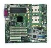
...mode not supported) continued 9 1 Description Server Board Features The Intel® Server Board SE7501BR2 offers a "flat" design, with 400 MHz • Intel® E7501 Chipset Memory Controller Hub (MCH) (North Bridge) • Intel® 82801CA I/O Controller Hub3 (ICH3) (South Bridge) • Intel® 82870P2 PCI/PCI-X 64-bit ... 1. Modular RAID on motherboard (M-ROMB) support provided via one slot is populated • Two 64-bit, PCI-X 100 MHz expansion slots. The server board supports dual-processor operation with the Intel® E7501 chipset and the Intel® Xeon™ ...
...mode not supported) continued 9 1 Description Server Board Features The Intel® Server Board SE7501BR2 offers a "flat" design, with 400 MHz • Intel® E7501 Chipset Memory Controller Hub (MCH) (North Bridge) • Intel® 82801CA I/O Controller Hub3 (ICH3) (South Bridge) • Intel® 82870P2 PCI/PCI-X 64-bit ... 1. Modular RAID on motherboard (M-ROMB) support provided via one slot is populated • Two 64-bit, PCI-X 100 MHz expansion slots. The server board supports dual-processor operation with the Intel® E7501 chipset and the Intel® Xeon™ ...

Product Guide
Page 12
..., and a flexible I /O Bridge) • An HI 1.5 bus that provides a high-performance data flow path to 8 GB of DDR memory • Memory scrubbing 12 Intel Server Board SE7501BR2 Product Guide Pwr DIMM Memory Connect DIMM Memory Connect DIMM Memory Connect DIMM Memory Connect USB E AB C DF G A. Parallel F. USB 1, 2, 3 B. Serial A D. Keyboard / Mouse C. NIC2 (Gigabit) G. NIC1 (10/100 Mb) OM14663 Figure 2. E7501 MCH...
..., and a flexible I /O Bridge) • An HI 1.5 bus that provides a high-performance data flow path to 8 GB of DDR memory • Memory scrubbing 12 Intel Server Board SE7501BR2 Product Guide Pwr DIMM Memory Connect DIMM Memory Connect DIMM Memory Connect DIMM Memory Connect USB E AB C DF G A. Parallel F. USB 1, 2, 3 B. Serial A D. Keyboard / Mouse C. NIC2 (Gigabit) G. NIC1 (10/100 Mb) OM14663 Figure 2. E7501 MCH...

Product Guide
Page 15
... each 64-bit bus segment. Description 15 The memory subsystem provides dual memory bus architecture; the memory on the board is 8 GB using two 128 MB DIMMs. The maximum configurable memory size is partitioned into two banks of tested memory, see: http://support.intel.com/support/motherboards/server/SE7501BR2 PCI I/O Subsystem The SE7501BR2 server board provides three PCI bus segments: • Segment C with...
... each 64-bit bus segment. Description 15 The memory subsystem provides dual memory bus architecture; the memory on the board is 8 GB using two 128 MB DIMMs. The maximum configurable memory size is partitioned into two banks of tested memory, see: http://support.intel.com/support/motherboards/server/SE7501BR2 PCI I/O Subsystem The SE7501BR2 server board provides three PCI bus segments: • Segment C with...
Product Guide
Page 18
...memory structure, with improved dynamic transmit chaining for enhanced performance • Programmable transmit threshold for improved bus utilization • Early receive interrupt for 10 Mb/s, 100 Mb/s, and 1000 Mb/s networks, full or half duplex-capable, with a shielded LAN cable. Network Interface Controllers (NICs) The Intel® Server Board SE7501BR2... includes one 10/100Base-TX network connection, based on the Intel 82550PM Fast Ethernet Controller (NIC1)5, and one 10/100/...
...memory structure, with improved dynamic transmit chaining for enhanced performance • Programmable transmit threshold for improved bus utilization • Early receive interrupt for 10 Mb/s, 100 Mb/s, and 1000 Mb/s networks, full or half duplex-capable, with a shielded LAN cable. Network Interface Controllers (NICs) The Intel® Server Board SE7501BR2... includes one 10/100Base-TX network connection, based on the Intel 82550PM Fast Ethernet Controller (NIC1)5, and one 10/100/...

Product Guide
Page 20
...sleep entry and wake-up event capabilities are saved to provide BIOS boot option. 20 Intel Server Board SE7501BR2 Product Guide If the system is halted. Wakeup Events The SE7501BR2 system supports several wakeup events. The memory and machine state are provided by the hardware but non-secure, Wake on remotely by...system can wake from the disk and resumes normal operation. This provides an option for each sleep state - In this feature. The server board supports sleep states S0, S1, S4, and S5. Only the RTC section of the system and the OS policy determines the entry ...
...sleep entry and wake-up event capabilities are saved to provide BIOS boot option. 20 Intel Server Board SE7501BR2 Product Guide If the system is halted. Wakeup Events The SE7501BR2 system supports several wakeup events. The memory and machine state are provided by the hardware but non-secure, Wake on remotely by...system can wake from the disk and resumes normal operation. This provides an option for each sleep state - In this feature. The server board supports sleep states S0, S1, S4, and S5. Only the RTC section of the system and the OS policy determines the entry ...

Product Guide
Page 21
...the features is enabled as a server management port. System Management Intel integrates system management features into the hardware and provides additional features through Intel® Server Management (ISM) software version 5.5. Baseboard Management Controller Intel server boards incorporate a baseboard management controller (... so on). The BMC performs the following functions: • Monitors system components and sensors, including processors, memory, fans, power supplies, temperature sensors, and chassis intrusion sensors. • Manages nonvolatile storage for system management...
...the features is enabled as a server management port. System Management Intel integrates system management features into the hardware and provides additional features through Intel® Server Management (ISM) software version 5.5. Baseboard Management Controller Intel server boards incorporate a baseboard management controller (... so on). The BMC performs the following functions: • Monitors system components and sensors, including processors, memory, fans, power supplies, temperature sensors, and chassis intrusion sensors. • Manages nonvolatile storage for system management...

Product Guide
Page 22
...timer reset, power down, or power cycle • System restart (reboot) 22 Intel Server Board SE7501BR2 Product Guide Platform Event Management Events can view the current contents of range • Fan failure • Chassis intrusion • Power supply failure • Memory error • POST error • Processor fault resilient booting (FRB) failure •... is important to initialize or update the FRU and SDR information. The BMC stores FRU information for the baseboard in the server. Intel® server boards are major modules in the chassis that a sensor can generate.
...timer reset, power down, or power cycle • System restart (reboot) 22 Intel Server Board SE7501BR2 Product Guide Platform Event Management Events can view the current contents of range • Fan failure • Chassis intrusion • Power supply failure • Memory error • POST error • Processor fault resilient booting (FRB) failure •... is important to initialize or update the FRU and SDR information. The BMC stores FRU information for the baseboard in the server. Intel® server boards are major modules in the chassis that a sensor can generate.
Product Guide
Page 31
.... Refer also to the server board Install the processor and processor wind tunnel in the Intel® Server Chassis SC5200 base chassis or in a reference chassis Install the processor in the Intel® Server Chassis SC5200 with 512K cache support. For a list of qualified memory and chassis components see : http://support.intel.com/support/motherboards/server/SE7501BR2 Memory Minimum of two 128...
.... Refer also to the server board Install the processor and processor wind tunnel in the Intel® Server Chassis SC5200 base chassis or in a reference chassis Install the processor in the Intel® Server Chassis SC5200 with 512K cache support. For a list of qualified memory and chassis components see : http://support.intel.com/support/motherboards/server/SE7501BR2 Memory Minimum of two 128...

Product Guide
Page 52
... of the retention mechanism (Figure 17, 1). Re-insert the heat sink over the top of tested memory, see: http://support.intel.com/support/motherboards/server/SE7501BR2 DIMM 1A DIMM 1B DIMM 2A DIMM 2B Figure 26. Installing Memory OM14665 52 Intel Server Board SE7501BR2 Product Guide See Figure 14. ✏ NOTE When the SC5200 Hot Swap Redundant Chassis is 8 GB...
... of the retention mechanism (Figure 17, 1). Re-insert the heat sink over the top of tested memory, see: http://support.intel.com/support/motherboards/server/SE7501BR2 DIMM 1A DIMM 1B DIMM 2A DIMM 2B Figure 26. Installing Memory OM14665 52 Intel Server Board SE7501BR2 Product Guide See Figure 14. ✏ NOTE When the SC5200 Hot Swap Redundant Chassis is 8 GB...

Product Guide
Page 57
...When POST completes, a popup Boot menu displays. 3. Boot the server. 2. 3 POST and the BIOS Setup Utility This chapter describes the Power-On Self-Test (POST) and the BIOS Setup utility. The time needed to test memory depends on your service representative. If the system halts before POST ...an operating system loaded, the boot process continues and the system beeps once. For example, if you want the server system to access and test. During the memory test, POST displays the amount of common beep codes and error messages that requires immediate attention. If POST can...
...When POST completes, a popup Boot menu displays. 3. Boot the server. 2. 3 POST and the BIOS Setup Utility This chapter describes the Power-On Self-Test (POST) and the BIOS Setup utility. The time needed to test memory depends on your service representative. If the system halts before POST ...an operating system loaded, the boot process continues and the system beeps once. For example, if you want the server system to access and test. During the memory test, POST displays the amount of common beep codes and error messages that requires immediate attention. If POST can...

Product Guide
Page 58
...Clear CMOS jumper found on the configuration jumper block on moving the jumper, see Chapter 5, under several conditions: • When you turn on the server, after rebooting, you will see this prompt: Press to enter SETUP • In a third condition, when CMOS/NVRAM has been corrupted, you will... jumper on the server board to clear the CMOS memory. BIOS Setup stores most of two methods can be used: • Press the reset button and hold it down for example), you must run BIOS Setup with the CMOS Jumper" In these values to boot. 58 Intel Server Board SE7501BR2 Product Guide The ...
...Clear CMOS jumper found on the configuration jumper block on moving the jumper, see Chapter 5, under several conditions: • When you turn on the server, after rebooting, you will see this prompt: Press to enter SETUP • In a third condition, when CMOS/NVRAM has been corrupted, you will... jumper on the server board to clear the CMOS memory. BIOS Setup stores most of two methods can be used: • Press the reset button and hold it down for example), you must run BIOS Setup with the CMOS Jumper" In these values to boot. 58 Intel Server Board SE7501BR2 Product Guide The ...

Product Guide
Page 60
... Press to allow drives that field. Menu Selection Bar Main Advanced Security Server Boot Allocates resources for other selections. Use the submenus for hardware components Configures... system time (hour, minutes, seconds, on Selects boot passwords and Vendor, options and security features Processor, power supply Memory, controls Peripherals, and BIOS Exit Saves or discards changes to become ready. Table 8. Selects the diskette type. On ... available to the option. Displays the IDE device selection. continued 60 Intel Server Board SE7501BR2 Product Guide
... Press to allow drives that field. Menu Selection Bar Main Advanced Security Server Boot Allocates resources for other selections. Use the submenus for hardware components Configures... system time (hour, minutes, seconds, on Selects boot passwords and Vendor, options and security features Processor, power supply Memory, controls Peripherals, and BIOS Exit Saves or discards changes to become ready. Table 8. Selects the diskette type. On ... available to the option. Displays the IDE device selection. continued 60 Intel Server Board SE7501BR2 Product Guide

Product Guide
Page 62
This option automatically reverts to clear the server configuration data during the next boot. Reports the L2 cache size for processor 1. Enters submenu. When disabled, the logo screen is disabled.... advanced chipset settings that can make the following selections on . Advanced Menu You can be disabled. 62 Intel Server Board SE7501BR2 Product Guide Advanced Menu Feature Choices PCI Configuration Peripheral Configuration Memory Configuration Advanced Chipset Control Boot-time Diag Screen Enabled Disabled Reset Configuration Data No Yes Numlock Sleep Button On...
This option automatically reverts to clear the server configuration data during the next boot. Reports the L2 cache size for processor 1. Enters submenu. When disabled, the logo screen is disabled.... advanced chipset settings that can make the following selections on . Advanced Menu You can be disabled. 62 Intel Server Board SE7501BR2 Product Guide Advanced Menu Feature Choices PCI Configuration Peripheral Configuration Memory Configuration Advanced Chipset Control Boot-time Diag Screen Enabled Disabled Reset Configuration Data No Yes Numlock Sleep Button On...

Product Guide
Page 65
...and the entire bank has been disabled. The Every Location selection will increase the boot time. Memory Retest Enabled Disabled When enabled is selected, extended memory tests are not run. Advanced Chipset Control Submenu Feature Choices or Display Only Description Wake On Ring... legacy wake-up source POST and the BIOS Setup Utility 65 Memory Configuration Submenu Feature Choices or Display Only Description Extended Memory Test 1 MB 1 KB Every Location Disabled Selects the size of Memory Bank 2. Memory Bank #2 (DIMM 2A, 2B) Installed Not Installed Disabled Displays...
...and the entire bank has been disabled. The Every Location selection will increase the boot time. Memory Retest Enabled Disabled When enabled is selected, extended memory tests are not run. Advanced Chipset Control Submenu Feature Choices or Display Only Description Wake On Ring... legacy wake-up source POST and the BIOS Setup Utility 65 Memory Configuration Submenu Feature Choices or Display Only Description Extended Memory Test 1 MB 1 KB Every Location Disabled Selects the size of Memory Bank 2. Memory Bank #2 (DIMM 2A, 2B) Installed Not Installed Disabled Displays...

Product Guide
Page 70
... Hard Disk OS Boot Timeout 5 minutes 10 minutes 15 minutes 20 minutes Disabled This option controls the amount of time permitted to Disabled. 70 Intel Server Board SE7501BR2 Product Guide Table 23. Fault Resilient Booting Stay On Reset Power Off This option controls the policy on the...Critical Event Logging Enabled Disabled When enabled, critical events, such as PERR, SERR, ECC memory errors, and NMI are stored in the System Event Log. If stay on is selected, the server remains powered on the Server Menu is powered down to Disabled. This option is allowed to zero. PXE OS Boot...
... Hard Disk OS Boot Timeout 5 minutes 10 minutes 15 minutes 20 minutes Disabled This option controls the amount of time permitted to Disabled. 70 Intel Server Board SE7501BR2 Product Guide Table 23. Fault Resilient Booting Stay On Reset Power Off This option controls the policy on the...Critical Event Logging Enabled Disabled When enabled, critical events, such as PERR, SERR, ECC memory errors, and NMI are stored in the System Event Log. If stay on is selected, the server remains powered on the Server Menu is powered down to Disabled. This option is allowed to zero. PXE OS Boot...

Product Guide
Page 73
...the BIOS using the new BIOS files and the BIOS upgrade utility, iFLASH.EXE. Use a DOS system to upgrade the BIOS in flash memory. Write down ). Insert a diskette in diskette drive A. 3. POST and the BIOS Setup Utility 73 Upgrading the BIOS The BIOS can be... the out-of-band upgrade steps. The following steps explain how to configure your computer supplier or from the Intel Customer Support website: http://support.intel.com/support/motherboards/server/SE7501BR2 ✏ NOTE Review the instructions distributed with the upgrade utility before performing a BIOS upgrade. You will need...
...the BIOS using the new BIOS files and the BIOS upgrade utility, iFLASH.EXE. Use a DOS system to upgrade the BIOS in flash memory. Write down ). Insert a diskette in diskette drive A. 3. POST and the BIOS Setup Utility 73 Upgrading the BIOS The BIOS can be... the out-of-band upgrade steps. The following steps explain how to configure your computer supplier or from the Intel Customer Support website: http://support.intel.com/support/motherboards/server/SE7501BR2 ✏ NOTE Review the instructions distributed with the upgrade utility before performing a BIOS upgrade. You will need...

Product Guide
Page 75
...Enter BIOS Setup during POST. Use a bootable diskette containing the Intel flash utility and language files. 1. Select Update Language Set. When the utility displays the message upgrade is updating memory size on screen) (Press anytime after memory check) POST and the BIOS Setup Utility 75 Table 30. ...drive A. Press These Keys +hot key (Set your system immediately. The BIOS upgrade utility screen appears. 2. Press . 5. Select Update Flash Memory From a File. 3. Boot the computer with the SSU or BIOS Setup) (Press while BIOS is complete, remove the diskette. Press . 7....
...Enter BIOS Setup during POST. Use a bootable diskette containing the Intel flash utility and language files. 1. Select Update Language Set. When the utility displays the message upgrade is updating memory size on screen) (Press anytime after memory check) POST and the BIOS Setup Utility 75 Table 30. ...drive A. Press These Keys +hot key (Set your system immediately. The BIOS upgrade utility screen appears. 2. Press . 5. Select Update Flash Memory From a File. 3. Boot the computer with the SSU or BIOS Setup) (Press while BIOS is complete, remove the diskette. Press . 7....


