
Product Guide
Page 3
Contents 1 Description Server Board Features ...7 Server Board Connector and Component Locations 8 Back Panel Connectors 9 Processor ...10 Memory ...10 PCI Riser Slots ...10 Video ...11 SCSI Controller ...11 ATA-100 Controller...11 IDE RAID...Procedures Install the I/O Shield ...21 Rearrange the Standoffs ...22 Server Board Bumpers ...23 Install the Server Board ...24 Installing Processors ...25 Install the Processor Terminator 28 Memory ...29 Connect Cables...30 3 Upgrading Tools and Supplies Needed 31 Cautions ...31 Memory ...32 Processors ...33 Adding or Replacing a Processor 34 Removing ...
Contents 1 Description Server Board Features ...7 Server Board Connector and Component Locations 8 Back Panel Connectors 9 Processor ...10 Memory ...10 PCI Riser Slots ...10 Video ...11 SCSI Controller ...11 ATA-100 Controller...11 IDE RAID...Procedures Install the I/O Shield ...21 Rearrange the Standoffs ...22 Server Board Bumpers ...23 Install the Server Board ...24 Installing Processors ...25 Install the Processor Terminator 28 Memory ...29 Connect Cables...30 3 Upgrading Tools and Supplies Needed 31 Cautions ...31 Memory ...32 Processors ...33 Adding or Replacing a Processor 34 Removing ...

Product Guide
Page 6
... Terminator 28 15. BMC LAN-Configuration Dialog 68 28. Platform Event Paging Dialog 67 27. Power Usage Worksheet 2 103 vi Intel Server Board SCB2 Product Guide Connect the Heat Sink Fan 36 22. System Setup Utility Main Window 59 25. BIOS Setup Menu Navigation 44 8..... Command Line Format 80 10. BIOS Setup Menu Display 45 9. Connecting Cables ...30 17. Installing Memory ...29 16. Jumper Locations ...91 Tables 1. Figures 1. Back Panel Connectors 9 3. Replacing the Back up Battery 40 24. Server Board Versions...7 2. Hot Keys ...42 7.
... Terminator 28 15. BMC LAN-Configuration Dialog 68 28. Platform Event Paging Dialog 67 27. Power Usage Worksheet 2 103 vi Intel Server Board SCB2 Product Guide Connect the Heat Sink Fan 36 22. System Setup Utility Main Window 59 25. BIOS Setup Menu Navigation 44 8..... Command Line Format 80 10. BIOS Setup Menu Display 45 9. Connecting Cables ...30 17. Installing Memory ...29 16. Jumper Locations ...91 Tables 1. Figures 1. Back Panel Connectors 9 3. Replacing the Back up Battery 40 24. Server Board Versions...7 2. Hot Keys ...42 7.
Product Guide
Page 7
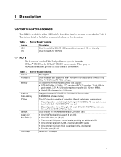
... low-profile (LP) 1.2-inch DIMMs. Graphics • Up to both server board versions. Video Memory 8 MB SDRAM of video memory PCI bus Two PCI riser slots capable of supporting either the 1U Intel® SR1200 or the 2U Intel® SR2200 server chassis. 1 Description Server Board Features The SCB2 is available in either SCSI or ATA hard drive interface versions...
... low-profile (LP) 1.2-inch DIMMs. Graphics • Up to both server board versions. Video Memory 8 MB SDRAM of video memory PCI bus Two PCI riser slots capable of supporting either the 1U Intel® SR1200 or the 2U Intel® SR2200 server chassis. 1 Description Server Board Features The SCB2 is available in either SCSI or ATA hard drive interface versions...
Product Guide
Page 10
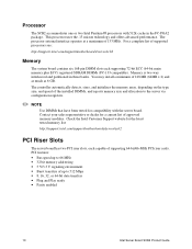
... supported processors see: http://support.intel.com/support/motherboards/server/scb2 Memory The system board contains six 168-pin DIMM slots each capable of supporting 64-bit/66-MHz PCI riser cards. Check the Intel Customer Support website for the latest tested memory list: http://support.intel.com/support/motherboards/server/scb2 PCI Riser Slots The server board has two PCI riser slots, each...
... supported processors see: http://support.intel.com/support/motherboards/server/scb2 Memory The system board contains six 168-pin DIMM slots each capable of supporting 64-bit/66-MHz PCI riser cards. Check the Intel Customer Support website for the latest tested memory list: http://support.intel.com/support/motherboards/server/scb2 PCI Riser Slots The server board has two PCI riser slots, each...

Product Guide
Page 12
...820.3u auto-negotiation support • Chained memory structure similar to the 82559, 82558, 82557 and 82596 • Full duplex support at both a network interface and server management interface. Network Teaming Features ✏ ...server management access. Whenever a disk write is performed, the controller sends data simultaneously to a secondary drive. It creates an identical drive backup to a second drive located on -board NICs in a team does not allow the use of its drives. To support both on a different data channel. With 4 drives attached to NIC 2. 12 Intel Server Board SCB2...
...820.3u auto-negotiation support • Chained memory structure similar to the 82559, 82558, 82557 and 82596 • Full duplex support at both a network interface and server management interface. Network Teaming Features ✏ ...server management access. Whenever a disk write is performed, the controller sends data simultaneously to a secondary drive. It creates an identical drive backup to a second drive located on -board NICs in a team does not allow the use of its drives. To support both on a different data channel. With 4 drives attached to NIC 2. 12 Intel Server Board SCB2...

Product Guide
Page 16
... Advanced Configuration and Power Interface (ACPI) as it was off. • s5: Soft off only when the AC power cord is disconnected. 16 Intel Server Board SCB2 Product Guide CAUTION The system is off : Only the RTC section of the CSB and the BMC are saved to -DB9 adapter should also match ...and the processors will still be lost in this state and the processor caches will maintain coherency. • s4: Hibernate or Save to Disk: The memory and machine state are running state. • s1: Processor sleep state. No context will be dissipating some power, so the power supply fans will ...
... Advanced Configuration and Power Interface (ACPI) as it was off. • s5: Soft off only when the AC power cord is disconnected. 16 Intel Server Board SCB2 Product Guide CAUTION The system is off : Only the RTC section of the CSB and the BMC are saved to -DB9 adapter should also match ...and the processors will still be lost in this state and the processor caches will maintain coherency. • s4: Hibernate or Save to Disk: The memory and machine state are running state. • s1: Processor sleep state. No context will be dissipating some power, so the power supply fans will ...

Product Guide
Page 29
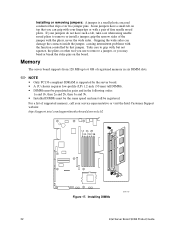
For a list of registered, ECC memory, using up to 6 GB of supported memory, call your service representative or visit the Intel Support website: http://support.intel.com/support/motherboards/server 1A 3A 2B 2A 1B 3B Figure 15. Install from 128 MB to six DIMMs. A 1U chassis requires low-profile (LP)... must all be installed in pairs and in the following order: 1a and 1b, 2a and 2b, 3a and 3b. Installing Memory OM11715 Installation Procedures 29 Memory Only PC133-compliant SDRAM is supported by the server board. Installed DIMMs must be the same speed and must be registered.
For a list of registered, ECC memory, using up to 6 GB of supported memory, call your service representative or visit the Intel Support website: http://support.intel.com/support/motherboards/server 1A 3A 2B 2A 1B 3B Figure 15. Install from 128 MB to six DIMMs. A 1U chassis requires low-profile (LP)... must all be installed in pairs and in the following order: 1a and 1b, 2a and 2b, 3a and 3b. Installing Memory OM11715 Installation Procedures 29 Memory Only PC133-compliant SDRAM is supported by the server board. Installed DIMMs must be the same speed and must be registered.
Product Guide
Page 32
...the pliers, never the wide sides. Memory The server board supports from 128 MB up to 6 GB of the jumper with a pair of supported memory, call your jumpers do not have a small tab on the board. grip the narrow sides of registered memory in the following order: 1a and... fine needle nosed pliers. If your service representative or visit the Intel Customer Support website: http://support.intel.com/support/motherboards/server/scb2 1A 3A 2B 2A 1B 3B Figure 17. Take care to grip with the function controlled by the server board. • A 1U chassis requires low-profile (LP) 1.2-inch...
...the pliers, never the wide sides. Memory The server board supports from 128 MB up to 6 GB of the jumper with a pair of supported memory, call your jumpers do not have a small tab on the board. grip the narrow sides of registered memory in the following order: 1a and... fine needle nosed pliers. If your service representative or visit the Intel Customer Support website: http://support.intel.com/support/motherboards/server/scb2 1A 3A 2B 2A 1B 3B Figure 17. Take care to grip with the function controlled by the server board. • A 1U chassis requires low-profile (LP) 1.2-inch...
Product Guide
Page 42
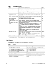
.... Information entered via the SSU/CSSU overrides information entered via the DPC console. You can move the CMOS jumper on screen.) (Press anytime after memory check.) 42 Intel Server Board SCB2 Product Guide Use to boot. Direct Platform Control (DPC) Console Use to update the BIOS or recover from a set of the SCSI host adapters...
.... Information entered via the SSU/CSSU overrides information entered via the DPC console. You can move the CMOS jumper on screen.) (Press anytime after memory check.) 42 Intel Server Board SCB2 Product Guide Use to boot. Direct Platform Control (DPC) Console Use to update the BIOS or recover from a set of the SCSI host adapters...

Product Guide
Page 43
... priority for this time, pressing any key causes the system to configure the hardware. After a few seconds, POST begins to test memory depends on page 54. 4. The system searches all server board features, such as: • Defining the diskette drive • Defining the serial port(s) • Set time/date (to modify all removable...
... priority for this time, pressing any key causes the system to configure the hardware. After a few seconds, POST begins to test memory depends on page 54. 4. The system searches all server board features, such as: • Defining the diskette drive • Defining the serial port(s) • Set time/date (to modify all removable...

Product Guide
Page 44
... or more, and then, while holding the reset button down, press the power button. If default values ever need to setup the following: • Enable Server Management Features • Read System Event Log (SEL) • Read Sensor Data Records • Read System FRU Information • Specify boot device sequence •... you cannot use BIOS Setup to correct the problem, you must run BIOS Setup again. Run the System Setup Utility (SSU) to clear CMOS memory. BIOS Setup Menu Navigation To: Get general help Move between menus Go to the previous item Go to the next Item Change the value of...
... or more, and then, while holding the reset button down, press the power button. If default values ever need to setup the following: • Enable Server Management Features • Read System Event Log (SEL) • Read Sensor Data Records • Read System FRU Information • Specify boot device sequence •... you cannot use BIOS Setup to correct the problem, you must run BIOS Setup again. Run the System Setup Utility (SSU) to clear CMOS memory. BIOS Setup Menu Navigation To: Get general help Move between menus Go to the previous item Go to the next Item Change the value of...

Product Guide
Page 46
... not appear if processor 1 is absent or disabled. System automatically resets to No in the system. Advanced Menu Feature PCI Configuration Peripheral Configuration Memory Configuration Advanced Chipset Control Reset Configuration Data Plug & Play O/S NumLock Choices Press Press Press Press No Yes No Yes Off On Description Enters ... "No" lets the BIOS configure all processors on the next boot. Reports the speed of the processor measured at power up. 46 Intel Server Board SCB2 Product Guide Select yes for the BIOS to clear the system configuration data during next boot.
... not appear if processor 1 is absent or disabled. System automatically resets to No in the system. Advanced Menu Feature PCI Configuration Peripheral Configuration Memory Configuration Advanced Chipset Control Reset Configuration Data Plug & Play O/S NumLock Choices Press Press Press Press No Yes No Yes Off On Description Enters ... "No" lets the BIOS configure all processors on the next boot. Reports the speed of the processor measured at power up. 46 Intel Server Board SCB2 Product Guide Select yes for the BIOS to clear the system configuration data during next boot.

Product Guide
Page 48
...be automatically reset to disabled on the next system boot. 48 Intel Server Board SCB2 Product Guide If console redirection is used, verify that the I /O and IRQ are present in the "Server Setup" menu. Used to enable the USB ports accessed through...baseboard. Used to configure the interrupt for serial port 2. Memory Configuration Submenu Feature Extended Memory Test Bank #1 Choices 1 MB 1 KB Every Location Disabled N/A Bank #2 N/A Bank #3 N/A Memory Retest Disabled Enabled Description Extended memory test options run during POST. Peripheral Configuration Submenu Feature ...
...be automatically reset to disabled on the next system boot. 48 Intel Server Board SCB2 Product Guide If console redirection is used, verify that the I /O and IRQ are present in the "Server Setup" menu. Used to enable the USB ports accessed through...baseboard. Used to configure the interrupt for serial port 2. Memory Configuration Submenu Feature Extended Memory Test Bank #1 Choices 1 MB 1 KB Every Location Disabled N/A Bank #2 N/A Bank #3 N/A Memory Retest Disabled Enabled Description Extended memory test options run during POST. Peripheral Configuration Submenu Feature ...

Product Guide
Page 51
... disallows flow control. XON/XOFF is used . These errors include PERR, SERR, ECC, Memory errors and NMI. When enabled, all systems events are fatal to XON/XOFF or XON/XOFF... Disabled Description Setting this option will detect and log events for server management features. CTS/RTS +CD is hardware based flow control. If enabled..., BIOS will disable the Quiet Boot option. System Management Submenu Feature Board Part Number Board Serial Number System Part Number System Serial Number Chassis Part Number Chassis Serial Number BIOS Revision BMC...
... disallows flow control. XON/XOFF is used . These errors include PERR, SERR, ECC, Memory errors and NMI. When enabled, all systems events are fatal to XON/XOFF or XON/XOFF... Disabled Description Setting this option will detect and log events for server management features. CTS/RTS +CD is hardware based flow control. If enabled..., BIOS will disable the Quiet Boot option. System Management Submenu Feature Board Part Number Board Serial Number System Part Number System Serial Number Chassis Part Number Chassis Serial Number BIOS Revision BMC...

Product Guide
Page 77
...settings, and obtaining the upgrade utility. To extract the BIOS.EXE file to the diskette, change to upgrade the BIOS in flash memory. The diskette now holds the BIOS upgrade and recovery files. Creating the BIOS Upgrade Diskette The BIOS upgrade file is a compressed ...C:\ prompt, change to upgrade the BIOS. 1. To extract the file, type the name of the BIOS from the Intel support website at: http://support.intel.com/support/motherboards/server/scb2 ✏ NOTE Print and review the release notes and instructions distributed with the upgrade utility before attempting a BIOS upgrade. ...
...settings, and obtaining the upgrade utility. To extract the BIOS.EXE file to the diskette, change to upgrade the BIOS in flash memory. The diskette now holds the BIOS upgrade and recovery files. Creating the BIOS Upgrade Diskette The BIOS upgrade file is a compressed ...C:\ prompt, change to upgrade the BIOS. 1. To extract the file, type the name of the BIOS from the Intel support website at: http://support.intel.com/support/motherboards/server/scb2 ✏ NOTE Print and review the release notes and instructions distributed with the upgrade utility before attempting a BIOS upgrade. ...

Product Guide
Page 80
...between blocks of two parameters. Parsing the Command Line The FRU/SDR load utility allows only one sensor for the utility. 80 Intel Server Board SCB2 Product Guide Using Specified CFG File Run the utility with the -d FRU or -d SDR command line flag, information about each instrumented...SDR Load Utility, Version Y.Y, Revision X.XX where Y.Y is the version number and X.XX is the revision number for each area is read from memory and printed on the screen. Command Line Format Command Description -? You can consist of data. A command line function can use either a slash...
...between blocks of two parameters. Parsing the Command Line The FRU/SDR load utility allows only one sensor for the utility. 80 Intel Server Board SCB2 Product Guide Using Specified CFG File Run the utility with the -d FRU or -d SDR command line flag, information about each instrumented...SDR Load Utility, Version Y.Y, Revision X.XX where Y.Y is the version number and X.XX is the revision number for each area is read from memory and printed on the screen. Command Line Format Command Description -? You can consist of data. A command line function can use either a slash...

Product Guide
Page 83
...that comes with them. q Are the configuration settings made in their slots on the Support website. Refer to the SCB2 Trouble Shooting Guide on the server board? Check the tested memory, and chassis lists, as well as the supported hardware and operating system list on light should be lit)? If...or processor termination board fully seated in BIOS Setup correct? 5 Solving Problems This chapter helps you identify and solve problems that might occur while you press the system power on/off switch on the front panel to turn the server on (power on the Intel Customer Support website....
...that comes with them. q Are the configuration settings made in their slots on the Support website. Refer to the SCB2 Trouble Shooting Guide on the server board? Check the tested memory, and chassis lists, as well as the supported hardware and operating system list on light should be lit)? If...or processor termination board fully seated in BIOS Setup correct? 5 Solving Problems This chapter helps you identify and solve problems that might occur while you press the system power on/off switch on the front panel to turn the server on (power on the Intel Customer Support website....

Product Guide
Page 93
...next. 1Ah G Off G R Check Refresh Toggle: The memory refresh line is 28h G Off R Off complete. Interrupt...color mode settings next. 29h G Off R G Debugger Hook 2Ah G Off A Off Init PCI devices and motherboard devices. Table 11. Displaying the power-on message, BIOS ID and processor information. 38h G Off R R ... to begin 25h Off G R G Init interrupt Vectors: Interrupt vector initialization is detected. 2Dh G G R G Scan flash for appliance servers only. 12h Off Off G R Check point After CMOS Initialized 27h Off G A G Validate date and time in BIOS data area....
...next. 1Ah G Off G R Check Refresh Toggle: The memory refresh line is 28h G Off R Off complete. Interrupt...color mode settings next. 29h G Off R G Debugger Hook 2Ah G Off A Off Init PCI devices and motherboard devices. Table 11. Displaying the power-on message, BIOS ID and processor information. 38h G Off R R ... to begin 25h Off G R G Init interrupt Vectors: Interrupt vector initialization is detected. 2Dh G G R G Scan flash for appliance servers only. 12h Off Off G R Check point After CMOS Initialized 27h Off G A G Validate date and time in BIOS data area....

Product Guide
Page 94
...the keyboard controller interface test command next. Checking for a locked key next 84h R G Off Off Verify RAM Size: Checking for a memory size mismatch with CMOS RAM data next 84h R G Off Off Check ATA Cable Type presence of ATAPI devices 84h R G Off ... Off Off R returned control to checkpoint 4Eh next. 57h Off A G A Chipset hook after the option ROM returned control. continued 94 Intel Server Board SCB2 Product Guide Check Stuck Key Enable Keyboard: The keyboard controller 82h R Off G Off interface test completed. Performing any required programming before Setup next...
...the keyboard controller interface test command next. Checking for a locked key next 84h R G Off Off Verify RAM Size: Checking for a memory size mismatch with CMOS RAM data next 84h R G Off Off Check ATA Cable Type presence of ATAPI devices 84h R G Off ... Off Off R returned control to checkpoint 4Eh next. 57h Off A G A Chipset hook after the option ROM returned control. continued 94 Intel Server Board SCB2 Product Guide Check Stuck Key Enable Keyboard: The keyboard controller 82h R Off G Off interface test completed. Performing any required programming before Setup next...

Product Guide
Page 95
... test next. 9Eh A G G R Enable Interrupts 0,1,2: Checking the extended keyboard, keyboard ID, and NUM Lock key next. Table 11. Execute setup. 8Bh A Off G G Set Base Expansion Memory Size 8Ch A G Off Off Adjust Setup: Programming the Setup options next. A5h R G R G Set Display Mode A7h R G A G OEM Patch 12 A7h R G A G Build SMBIOS table and MP...
... test next. 9Eh A G G R Enable Interrupts 0,1,2: Checking the extended keyboard, keyboard ID, and NUM Lock key next. Table 11. Execute setup. 8Bh A Off G G Set Base Expansion Memory Size 8Ch A G Off Off Adjust Setup: Programming the Setup options next. A5h R G R G Set Display Mode A7h R G A G OEM Patch 12 A7h R G A G Build SMBIOS table and MP...


