
User Guide
Page 5
... version of this book, you will find technical specifications, regulatory information, "getting help you identify components and their locations. At the back of this manual, see http:/ /support.intel.com/support/motherboards/server/chassis/sc5299-e/. Product Contents, Order Options, and Accessories This server chassis is written for system technicians who are responsible for troubleshooting, upgrading, and repairing this chapter for step-by-step instructions and diagrams for purchasing and using...
... version of this book, you will find technical specifications, regulatory information, "getting help you identify components and their locations. At the back of this manual, see http:/ /support.intel.com/support/motherboards/server/chassis/sc5299-e/. Product Contents, Order Options, and Accessories This server chassis is written for system technicians who are responsible for troubleshooting, upgrading, and repairing this chapter for step-by-step instructions and diagrams for purchasing and using...
User Guide
Page 6
..., processors, and third-party hardware have been tested and can be used with your server: Processor, memory FBDIMMs, hard drive, CD-ROM or DVD-ROM drive, RAID controller, operating system. Additional Information and Software If you purchased. For this Document or Software Intel® Entry Server Chassis SC5299-E Technical Product Specification Intel® Entry Server Chassis SC5299-E Quick Start User's Guide in the product box vi Intel® Entry Server Chassis SC5299-E UP/DP/WS/BRP User Guide Wattage of power supply will depend on this Web page, type the document or software...
..., processors, and third-party hardware have been tested and can be used with your server: Processor, memory FBDIMMs, hard drive, CD-ROM or DVD-ROM drive, RAID controller, operating system. Additional Information and Software If you purchased. For this Document or Software Intel® Entry Server Chassis SC5299-E Technical Product Specification Intel® Entry Server Chassis SC5299-E Quick Start User's Guide in the product box vi Intel® Entry Server Chassis SC5299-E UP/DP/WS/BRP User Guide Wattage of power supply will depend on this Web page, type the document or software...
User Guide
Page 7
Preface For this information or software Use this Document or Software For virtual system tours and interactive repair information A link to the SMaRT Tool is available under "Other Resources" at the right side of the screen at http://support.intel.com/support/motherboards/server/chassis/ sc5299-e Accessories or other Intel Spares and Configuration Guide server products Hardware (peripheral boards, adapter cards) and operating systems that have been tested with this product Tested Hardware/Operating Systems List To make sure your...
Preface For this information or software Use this Document or Software For virtual system tours and interactive repair information A link to the SMaRT Tool is available under "Other Resources" at the right side of the screen at http://support.intel.com/support/motherboards/server/chassis/ sc5299-e Accessories or other Intel Spares and Configuration Guide server products Hardware (peripheral boards, adapter cards) and operating systems that have been tested with this product Tested Hardware/Operating Systems List To make sure your...
User Guide
Page 9
... Software vi Server Chassis Features 1 Component Identification ...3 Front View Components 3 Internal Components ...5 Back Panel Components 7 Front Panel ...8 Peripheral Devices ...9 Hard Disk Drives ...9 Front Bezel Assembly ...10 Rack-Mounted Systems ...10 Mechanical Locks ...11 Accessories and Order Codes 11 Hardware Installations and Upgrades 13 Before You Begin ...13 Tools and Supplies Needed 13 System References ...13 Removing and Installing the Left Side Cover 13 Removing the Left Side Cover 13 Installing the Left Side Cover 14 Removing...
... Software vi Server Chassis Features 1 Component Identification ...3 Front View Components 3 Internal Components ...5 Back Panel Components 7 Front Panel ...8 Peripheral Devices ...9 Hard Disk Drives ...9 Front Bezel Assembly ...10 Rack-Mounted Systems ...10 Mechanical Locks ...11 Accessories and Order Codes 11 Hardware Installations and Upgrades 13 Before You Begin ...13 Tools and Supplies Needed 13 System References ...13 Removing and Installing the Left Side Cover 13 Removing the Left Side Cover 13 Installing the Left Side Cover 14 Removing...
User Guide
Page 10
...Access Warnings 99 Rack Mount Warnings 100 x Intel® Entry Server Chassis SC5299-E UP/DP/WS/BRP User Guide Removing a Fixed Hard Drive 32 Installing or Removing a DVD-ROM or CD-ROM Drive 35 Installing a DVD-ROM or CD-ROM Drive 35 Removing a CD-ROM or DVD-ROM Drive 37 Installing the Removing PCI Add-in Boards 38 Installing PCI Add-in Boards 38 Removing PCI Add-in Boards 40 Replacing the Front Panel Board 42 Replacing a System Fan ...46 Replacing a Fixed Power Supply 49 Installing an Additional Hot Swap Power Supply Module (BRP configuration only 52 Replacing a Hot Swap Power...
...Access Warnings 99 Rack Mount Warnings 100 x Intel® Entry Server Chassis SC5299-E UP/DP/WS/BRP User Guide Removing a Fixed Hard Drive 32 Installing or Removing a DVD-ROM or CD-ROM Drive 35 Installing a DVD-ROM or CD-ROM Drive 35 Removing a CD-ROM or DVD-ROM Drive 37 Installing the Removing PCI Add-in Boards 38 Installing PCI Add-in Boards 38 Removing PCI Add-in Boards 40 Replacing the Front Panel Board 42 Replacing a System Fan ...46 Replacing a Fixed Power Supply 49 Installing an Additional Hot Swap Power Supply Module (BRP configuration only 52 Replacing a Hot Swap Power...

User Guide
Page 13
.... List of Intel® Entry Server Chassis SC5299-E 1 Figure 2. Removing PCI Card Guide 28 Figure 27. Preparing Fixed Hard Drive for Removal 34 Figure 37. Back Panel Components 7 Figure 7. Optional Peripheral Devices (DP/WS/BRP configuration shown 9 Figure 9. Internal Components (UP Configuration 6 Figure 6. Removing Front Bezel Assembly (DP/WS/BRP configuration shown 17 Figure 15. Inserting Fixed Hard Drive Cage into Chassis 23 Figure 22. Removing Processor Air Duct 19 Figure 17. Routing Hard Drive Power Cables 28...
.... List of Intel® Entry Server Chassis SC5299-E 1 Figure 2. Removing PCI Card Guide 28 Figure 27. Preparing Fixed Hard Drive for Removal 34 Figure 37. Back Panel Components 7 Figure 7. Optional Peripheral Devices (DP/WS/BRP configuration shown 9 Figure 9. Internal Components (UP Configuration 6 Figure 6. Removing Front Bezel Assembly (DP/WS/BRP configuration shown 17 Figure 15. Inserting Fixed Hard Drive Cage into Chassis 23 Figure 22. Removing Processor Air Duct 19 Figure 17. Routing Hard Drive Power Cables 28...

User Guide
Page 14
.... Opening PCI Add-in Chassis 50 Figure 63. Inserting Fixed Power Supply in Card Retention Device (DP/WS/BRP configuration shown) .. 41 Figure 47. Removing Hot Swap Power Supply Module from Hot Swap Drive Cage 64 Figure 80. Detaching Hot Swap Power Supply Cage from Inside of Chassis 55 Figure 71. Attaching Filler Panel to Hot Swap Drive Cage (SAS/SATA drive cage illustrated).. 66 xiv Intel® Entry Server Chassis SC5299-E UP/DP/WS/BRP User Guide Detaching Hot Swap Power Supply Cage from Chassis...
.... Opening PCI Add-in Chassis 50 Figure 63. Inserting Fixed Power Supply in Card Retention Device (DP/WS/BRP configuration shown) .. 41 Figure 47. Removing Hot Swap Power Supply Module from Hot Swap Drive Cage 64 Figure 80. Detaching Hot Swap Power Supply Cage from Inside of Chassis 55 Figure 71. Attaching Filler Panel to Hot Swap Drive Cage (SAS/SATA drive cage illustrated).. 66 xiv Intel® Entry Server Chassis SC5299-E UP/DP/WS/BRP User Guide Detaching Hot Swap Power Supply Cage from Chassis...

User Guide
Page 27
... 3 for installing hard drives, a floppy drive, a CD-ROM drive, a DVD-ROM drive or a tape drive. Figure 8. For instructions on installing hard drives, see "Installing and Removing a Fixed Hard Drive". Optional Peripheral Devices (DP/WS/BRP configuration shown) Hard Disk Drives The server chassis ships with one fixed hard drive cage capable of supporting up to six hot-swappable SCSI, SATA or SAS hard drives) may limit the maximum number of handling up to replace the fixed hard drive cage. An optional hot-swap SCSI or SAS/SATA backplane hard drive cage (capable of drives that screws...
... 3 for installing hard drives, a floppy drive, a CD-ROM drive, a DVD-ROM drive or a tape drive. Figure 8. For instructions on installing hard drives, see "Installing and Removing a Fixed Hard Drive". Optional Peripheral Devices (DP/WS/BRP configuration shown) Hard Disk Drives The server chassis ships with one fixed hard drive cage capable of supporting up to six hot-swappable SCSI, SATA or SAS hard drives) may limit the maximum number of handling up to replace the fixed hard drive cage. An optional hot-swap SCSI or SAS/SATA backplane hard drive cage (capable of drives that screws...

User Guide
Page 31
... side cover, power down the server and unplug all peripheral devices connected to left side cover to prevent the chassis from sliding on the server board, such as it would be needed to add or replace components inside of the chassis as the processor and memory FBDIMMs, see the instructions provided with your work surface. 1. Intel® Entry Server Chassis SC5299-E UP/DP/WS/BRP User Guide 13 2 Hardware Installations and Upgrades This document provides instructions...
... side cover, power down the server and unplug all peripheral devices connected to left side cover to prevent the chassis from sliding on the server board, such as it would be needed to add or replace components inside of the chassis as the processor and memory FBDIMMs, see the instructions provided with your work surface. 1. Intel® Entry Server Chassis SC5299-E UP/DP/WS/BRP User Guide 13 2 Hardware Installations and Upgrades This document provides instructions...

User Guide
Page 37
... UP configuration of the left side cover will also remove (or install) the attached ductwork.. Intel® Entry Server Chassis SC5299-E UP/DP/WS/BRP User Guide 19 Power down the server and unplug all peripheral devices and the AC power cable. 3. Removal (or installation) of the Intel® Entry Server Chassis SC5299-E. Removing the Processor Air Duct Note: The following removal and install procedures are not applicatible to re-install the processor air duct. Warning: The processor air...
... UP configuration of the left side cover will also remove (or install) the attached ductwork.. Intel® Entry Server Chassis SC5299-E UP/DP/WS/BRP User Guide 19 Power down the server and unplug all peripheral devices and the AC power cable. 3. Removal (or installation) of the Intel® Entry Server Chassis SC5299-E. Removing the Processor Air Duct Note: The following removal and install procedures are not applicatible to re-install the processor air duct. Warning: The processor air...

User Guide
Page 44
Installing a Fixed Hard Drive Caution: Fixed drives are NOT hot swappable. Drive Bay Slot Order 1. Note: The Intel® Entry Server Chassis SC5299-E does not support all peripheral devices connected to a list of drives that ships with the Intel® Entry Server Chassis SC5299-E. Before removing or replacing the drive, you must first take the server out of service, turn off all hard drives. Failure to six fixed hard drives can be installed in the fixed hard drive cage that can be populated first. Power down...
Installing a Fixed Hard Drive Caution: Fixed drives are NOT hot swappable. Drive Bay Slot Order 1. Note: The Intel® Entry Server Chassis SC5299-E does not support all peripheral devices connected to a list of drives that ships with the Intel® Entry Server Chassis SC5299-E. Before removing or replacing the drive, you must first take the server out of service, turn off all hard drives. Failure to six fixed hard drives can be installed in the fixed hard drive cage that can be populated first. Power down...

User Guide
Page 50
... power cable. 3. For instructions, see "Installing PCI Add-in the following figure). Before removing or replacing the drive, you must first take the server out of PCI card guide into the server. For instructions, see "Removing the Left Side Cover". 4. Re-install the left side cover. Re-install the front bezel assembly. For instructions, see "Removing and Installing the Front Bezel Assembly". 32 Intel® Entry Server Chassis SC5299-E UP/DP/WS/BRP User Guide Re-installing PCI Card Guide 16. Re-install the PCI card guide...
... power cable. 3. For instructions, see "Installing PCI Add-in the following figure). Before removing or replacing the drive, you must first take the server out of PCI card guide into the server. For instructions, see "Removing the Left Side Cover". 4. Re-install the left side cover. Re-install the front bezel assembly. For instructions, see "Removing and Installing the Front Bezel Assembly". 32 Intel® Entry Server Chassis SC5299-E UP/DP/WS/BRP User Guide Re-installing PCI Card Guide 16. Re-install the PCI card guide...

User Guide
Page 53
... power cable(s) into the server. For instructions, see "Removing the Left Side Cover". 4. Remove the EMI shield from the system or wall outlet. For instructions, see "Installing the Left Side Cover" 11. Installing or Removing a DVD-ROM or CD-ROM Drive Caution: CD-ROM and DVD-ROM drives are NOT hot swappable. Observe the safety and ESD precautions listed in Drive EMI Shield (DP/WS/BRP configuration shown) Intel® Entry Server Chassis SC5299-E UP/DP/WS/BRP User Guide...
... power cable(s) into the server. For instructions, see "Removing the Left Side Cover". 4. Remove the EMI shield from the system or wall outlet. For instructions, see "Installing the Left Side Cover" 11. Installing or Removing a DVD-ROM or CD-ROM Drive Caution: CD-ROM and DVD-ROM drives are NOT hot swappable. Observe the safety and ESD precautions listed in Drive EMI Shield (DP/WS/BRP configuration shown) Intel® Entry Server Chassis SC5299-E UP/DP/WS/BRP User Guide...

User Guide
Page 60
... devices and the AC power cable(s). For instructions, see "Removing the Front Bezel Assembly". 42 Intel® Entry Server Chassis SC5299-E UP/DP/WS/BRP User Guide Replacing PCI Slot Shield 8. Before removing or replacing the front panel board, you must be operated with a front panel board installed. Remove the left side cover. TP01726 Figure 48. Reconnect all peripheral devices and the AC power cable. 3. For instructions, see "Removing the Left Side Cover" 4. If available, replace the PCI slot shield by pressing the power button...
... devices and the AC power cable(s). For instructions, see "Removing the Front Bezel Assembly". 42 Intel® Entry Server Chassis SC5299-E UP/DP/WS/BRP User Guide Replacing PCI Slot Shield 8. Before removing or replacing the front panel board, you must be operated with a front panel board installed. Remove the left side cover. TP01726 Figure 48. Reconnect all peripheral devices and the AC power cable. 3. For instructions, see "Removing the Left Side Cover" 4. If available, replace the PCI slot shield by pressing the power button...
User Guide
Page 67
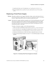
... by technically qualified personnel. Rotate the blue locking mechanism (see letter "A" in the following instructions: 1. To replace a fixed power supply, use the following figure to the system, turn off all internal power cables from the system or wall outlet. servicing of the Intel® Entry Server Chassis SC5299-E. Replacing a Fixed Power Supply Warning: Hazardous conditions, power supply: Hazardous voltage, current, and energy levels are no user-serviceable parts inside the power supply. Remove the left side cover. For instructions, see "Installing...
... by technically qualified personnel. Rotate the blue locking mechanism (see letter "A" in the following instructions: 1. To replace a fixed power supply, use the following figure to the system, turn off all internal power cables from the system or wall outlet. servicing of the Intel® Entry Server Chassis SC5299-E. Replacing a Fixed Power Supply Warning: Hazardous conditions, power supply: Hazardous voltage, current, and energy levels are no user-serviceable parts inside the power supply. Remove the left side cover. For instructions, see "Installing...

User Guide
Page 69
... the server board. Route and connect the P1, P2, and P14 cables to the locked position (see "Installing the Left Side Cover". 14. Hardware Installations and Upgrades 8. A TP01755 Figure 63. Refer to installed devices. Route the P8, P9, P10, and P12 cables to the hard drive cage and connect power cables to the Intel® Server Board Quick Start User's Guide or User Guide that came with SC5299DP/BRP configuration only: The +12V CPU power cable (P2) from the power supply...
... the server board. Route and connect the P1, P2, and P14 cables to the locked position (see "Installing the Left Side Cover". 14. Hardware Installations and Upgrades 8. A TP01755 Figure 63. Refer to installed devices. Route the P8, P9, P10, and P12 cables to the hard drive cage and connect power cables to the Intel® Server Board Quick Start User's Guide or User Guide that came with SC5299DP/BRP configuration only: The +12V CPU power cable (P2) from the power supply...

User Guide
Page 70
...". 2. The P12 cable will be done only by technically qualified personnel. UP UP TP00916 Figure 64. Removing Power Supply Filler Panel 3. TP00917 Figure 65. Insert finger into place. Note: For Intel® Server Board S3000AH with redundant power supply capability. Insert new hot swap power supply module until it ; Inserting Additional Hot Swap Power Supply Module 52 Intel® Entry Server Chassis SC5299-E UP/DP/WS/BRP User Guide servicing of filler panel and remove filler panel from chassis. . There...
...". 2. The P12 cable will be done only by technically qualified personnel. UP UP TP00916 Figure 64. Removing Power Supply Filler Panel 3. TP00917 Figure 65. Insert finger into place. Note: For Intel® Server Board S3000AH with redundant power supply capability. Insert new hot swap power supply module until it ; Inserting Additional Hot Swap Power Supply Module 52 Intel® Entry Server Chassis SC5299-E UP/DP/WS/BRP User Guide servicing of filler panel and remove filler panel from chassis. . There...

User Guide
Page 72
...handle to remove hot swap power supply module from chassis components and server board. 54 Intel® Entry Server Chassis SC5299-E UP/DP/WS/BRP User Guide Removing Hot Swap Power Supply Module 5. Observe the safety and ESD precautions listed in Appendix A, "Safety Information". 2. UP UP A TP01765 Figure 68. Remove the left side cover. Hardware Installations and Upgrades Replacing a Hot Swap Power Supply Cage (BRP configuration only) Warning: Hazardous conditions, power supply: Hazardous voltage, current, and energy levels are no user-serviceable parts inside the power supply.
...handle to remove hot swap power supply module from chassis components and server board. 54 Intel® Entry Server Chassis SC5299-E UP/DP/WS/BRP User Guide Removing Hot Swap Power Supply Module 5. Observe the safety and ESD precautions listed in Appendix A, "Safety Information". 2. UP UP A TP01765 Figure 68. Remove the left side cover. Hardware Installations and Upgrades Replacing a Hot Swap Power Supply Cage (BRP configuration only) Warning: Hazardous conditions, power supply: Hazardous voltage, current, and energy levels are no user-serviceable parts inside the power supply.

User Guide
Page 87
.../WS/BRP configuration shown) Intel® Entry Server Chassis SC5299-E UP/DP/WS/BRP User Guide 69 Connect the SCSI data cable (see letter "A" in data loss. Note: Connect the SES cable from the SAS/SATA backplane to your server board or RAID controller card. ii. Hot Swap Drive Cage Upgrade Install Instructions (optional) 17. Cable instructions will differ depending upon whether you are installing a SCSI or SAS/ SATA hot swap drive cage. For other Intel® server boards, refer to the SCSI connector on the SCSI backplane. Connect the two power cables (see letter...
.../WS/BRP configuration shown) Intel® Entry Server Chassis SC5299-E UP/DP/WS/BRP User Guide 69 Connect the SCSI data cable (see letter "A" in data loss. Note: Connect the SES cable from the SAS/SATA backplane to your server board or RAID controller card. ii. Hot Swap Drive Cage Upgrade Install Instructions (optional) 17. Cable instructions will differ depending upon whether you are installing a SCSI or SAS/ SATA hot swap drive cage. For other Intel® server boards, refer to the SCSI connector on the SCSI backplane. Connect the two power cables (see letter...

User Guide
Page 118
... disk drives, boards, and other fasteners when removing access cover(s). Caution: To avoid injury do not operate the system without the fan guard in the power supply. If one piece of equipment is not available, provide some ESD protection by their edges. Unless you perform all procedures at a time. The equipment rack must be extremely sensitive to prevent it . Use a 100 Intel® Entry Server Chassis SC5299...
... disk drives, boards, and other fasteners when removing access cover(s). Caution: To avoid injury do not operate the system without the fan guard in the power supply. If one piece of equipment is not available, provide some ESD protection by their edges. Unless you perform all procedures at a time. The equipment rack must be extremely sensitive to prevent it . Use a 100 Intel® Entry Server Chassis SC5299...


