
User Guide
Page 20
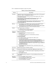
...-bit/133MHz PCI-X* connector • One 64-bit/100MHz PCI-X* connector • Two x4 PCI Express* connectors 2 Intel® Server Board S5000VSA User's Guide or 1333-MHz front side bus. Product codes S5000VSASATAR, S5000VSASASR, S5000VSASCSIR, and S5000VSA4DIMMR only. • Entry...Intel® Enterprise South Bridge (ESB2-E) External connections: • Stacked PS/2* ports for keyboard and mouse • DB9 Serial A port • Two RJ45 NIC connectors for 10/100/1000 Mb connections • Four USB 2.0 ports Internal connections: • One USB port header, which supports two USB...
...-bit/133MHz PCI-X* connector • One 64-bit/100MHz PCI-X* connector • Two x4 PCI Express* connectors 2 Intel® Server Board S5000VSA User's Guide or 1333-MHz front side bus. Product codes S5000VSASATAR, S5000VSASASR, S5000VSASCSIR, and S5000VSA4DIMMR only. • Entry...Intel® Enterprise South Bridge (ESB2-E) External connections: • Stacked PS/2* ports for keyboard and mouse • DB9 Serial A port • Two RJ45 NIC connectors for 10/100/1000 Mb connections • Four USB 2.0 ports Internal connections: • One USB port header, which supports two USB...
User Guide
Page 25
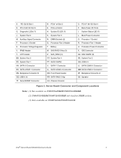
...(3) DD. Speaker Figure 2. Backplane Connector B QQ. USB 6 (1) TT. System Fan 5 N. System Status LED (1) L. Server Board Connector and Component Locations Notes: (1) Not available on S5000VSA4DIMM/S5000VSA4DIMMR. (2) S5000VSA4DIMM/S5000VSA4DIMMR only has four DIMM sockets. (3) Only available on S5000VSASAS/S5000VSASASR. Intel® Server Board S5000VSA User's Guide 7 PCIe x4 Slot 6 H. DIMM Sockets... PP. SATA RAID 5 Key UU. SATA 3/SAS 1 Connector NN. SAS_SES2 (3) CC. A. PCI 32/33 Slot 1 D. Processor 2 Socket S. USB 4-5 JJ. PCI-X 64/100 Slot 5 G. PCIe* x4 Slot 3 E.
...(3) DD. Speaker Figure 2. Backplane Connector B QQ. USB 6 (1) TT. System Fan 5 N. System Status LED (1) L. Server Board Connector and Component Locations Notes: (1) Not available on S5000VSA4DIMM/S5000VSA4DIMMR. (2) S5000VSA4DIMM/S5000VSA4DIMMR only has four DIMM sockets. (3) Only available on S5000VSASAS/S5000VSASASR. Intel® Server Board S5000VSA User's Guide 7 PCIe x4 Slot 6 H. DIMM Sockets... PP. SATA RAID 5 Key UU. SATA 3/SAS 1 Connector NN. SAS_SES2 (3) CC. A. PCI 32/33 Slot 1 D. Processor 2 Socket S. USB 4-5 JJ. PCI-X 64/100 Slot 5 G. PCIe* x4 Slot 3 E.

User Guide
Page 27
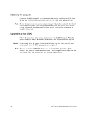
Back Panel Connectors A B C D H G F A. USB 0-1 H. USB 2-3 G. NIC 1 (10/100/1000 Mb) E. Serial Port B D. Back Panel Connectors E AF000184 The NIC LEDs at the right and left LED is on or blinking) 100 Mbps connection 1000 Mbps connection Intel® Server Board S5000VSA User's Guide 9 Table 3. Video B. NIC LED Descriptions LED Left Right LED State Off Solid Amber Blinking Amber...
Back Panel Connectors A B C D H G F A. USB 0-1 H. USB 2-3 G. NIC 1 (10/100/1000 Mb) E. Serial Port B D. Back Panel Connectors E AF000184 The NIC LEDs at the right and left LED is on or blinking) 100 Mbps connection 1000 Mbps connection Intel® Server Board S5000VSA User's Guide 9 Table 3. Video B. NIC LED Descriptions LED Left Right LED State Off Solid Amber Blinking Amber...
User Guide
Page 34
...a CMOS Checksum error or other information to a temporary folder on your settings, and exit Setup. 16 Intel® Server Board S5000VSA User's Guide If this happens, shut down the system during the BIOS update process! CMOS checksum errors require... that came with the BIOS image file before attempting a BIOS upgrade. When the update completes, remove the bootable media from which you enter Setup, check your settings, save your hard drive or a USB...
...a CMOS Checksum error or other information to a temporary folder on your settings, and exit Setup. 16 Intel® Server Board S5000VSA User's Guide If this happens, shut down the system during the BIOS update process! CMOS checksum errors require... that came with the BIOS image file before attempting a BIOS upgrade. When the update completes, remove the bootable media from which you enter Setup, check your settings, save your hard drive or a USB...

