

User Guide
Page 5
.... Hazardous conditions, devices and cables: Hazardous electrical conditions may bend or break the pins on /off: The power button DOES NOT turn off the server and disconnect the power cord, telecommunications systems, networks, and modems attached to chassis ground any other parts. ESD and handling boards: Always handle boards carefully. Intel® Server Board S5000VSA User's Guide v Warnings Heed safety instructions: Before working with existing product certifications and approvals. Use only the...
.... Hazardous conditions, devices and cables: Hazardous electrical conditions may bend or break the pins on /off: The power button DOES NOT turn off the server and disconnect the power cord, telecommunications systems, networks, and modems attached to chassis ground any other parts. ESD and handling boards: Always handle boards carefully. Intel® Server Board S5000VSA User's Guide v Warnings Heed safety instructions: Before working with existing product certifications and approvals. Use only the...
User Guide
Page 7
... specific BIOS settings and screens is written for troubleshooting, upgrading, and repairing this chapter, you may need, troubleshooting information, and instructions on how to add and replace components on using the Intel® Server Board S5000VSA. You will find suggestions for a link to identify the source of document. Manual Organization Chapter 1 provides a brief overview of this Manual Thank you for installing or replacing components such as the memory, processor, control panel board, and the battery...
... specific BIOS settings and screens is written for troubleshooting, upgrading, and repairing this chapter, you may need, troubleshooting information, and instructions on how to add and replace components on using the Intel® Server Board S5000VSA. You will find suggestions for a link to identify the source of document. Manual Organization Chapter 1 provides a brief overview of this Manual Thank you for installing or replacing components such as the memory, processor, control panel board, and the battery...
User Guide
Page 8
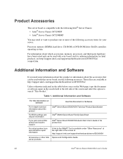
... http://support.intel.com/support/motherboards/server/S5000VSA/ Unless otherwise indicated in the table below, once on this product or information about which accessories, memory, processors, and third-party hardware have been tested and can be used with your server: Processor, memory DIMMs, hard drive, CD-ROM or DVD-ROM drive, RAID controller, operating system. Table 1. Product Accessories This server board is available under "Other Resources" at the right side of the screen...
... http://support.intel.com/support/motherboards/server/S5000VSA/ Unless otherwise indicated in the table below, once on this product or information about which accessories, memory, processors, and third-party hardware have been tested and can be used with your server: Processor, memory DIMMs, hard drive, CD-ROM or DVD-ROM drive, RAID controller, operating system. Table 1. Product Accessories This server board is available under "Other Resources" at the right side of the screen...
User Guide
Page 11
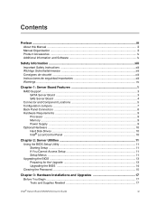
...xv Chapter 1: Server Board Features 1 RAID Support ...3 SATA Server Board ...3 SAS Server Board ...4 Connector and Component Locations 5 Configuration Jumpers ...7 Back Panel Connectors ...8 Hardware Requirements ...9 Processor ...9 Memory ...9 Power Supply ...9 Optional Hardware ...10 Hard Disk Drives ...10 Intel® Local Control Panel 10 Chapter 2: Server Utilities 11 Using the BIOS Setup Utility 11 Starting Setup ...11 If You Cannot Access Setup 11 Setup Menus ...11 Upgrading the BIOS ...13 Preparing for the Upgrade 13 Upgrading the BIOS ...14 Clearing the Password ...15 Chapter...
...xv Chapter 1: Server Board Features 1 RAID Support ...3 SATA Server Board ...3 SAS Server Board ...4 Connector and Component Locations 5 Configuration Jumpers ...7 Back Panel Connectors ...8 Hardware Requirements ...9 Processor ...9 Memory ...9 Power Supply ...9 Optional Hardware ...10 Hard Disk Drives ...10 Intel® Local Control Panel 10 Chapter 2: Server Utilities 11 Using the BIOS Setup Utility 11 Starting Setup ...11 If You Cannot Access Setup 11 Setup Menus ...11 Upgrading the BIOS ...13 Preparing for the Upgrade 13 Upgrading the BIOS ...14 Clearing the Password ...15 Chapter...

User Guide
Page 12
... Key System Lights 39 Confirming Loading of the Operating System 39 Specific Problems and Corrective Actions 39 Power Light Does Not Light 40 No Characters Appear on Screen 40 Characters Are Distorted or Incorrect 41 System Cooling Fans Do Not Rotate Properly 41 CD-ROM Drive or DVD-ROM Drive Activity Light Does Not Light 42 Cannot Connect to a Server 42 Problems with Network 42 System Boots when Installing PCI Card 43 Problems with Newly Installed Application Software...
... Key System Lights 39 Confirming Loading of the Operating System 39 Specific Problems and Corrective Actions 39 Power Light Does Not Light 40 No Characters Appear on Screen 40 Characters Are Distorted or Incorrect 41 System Cooling Fans Do Not Rotate Properly 41 CD-ROM Drive or DVD-ROM Drive Activity Light Does Not Light 42 Cannot Connect to a Server 42 Problems with Network 42 System Boots when Installing PCI Card 43 Problems with Newly Installed Application Software...
User Guide
Page 20
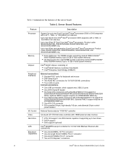
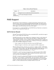
... drives • SATA support • SAS support (optional) Intel® 82563EB dual port controller for 10/100/1000 Mbit/sec Ethernet LAN connectivity • One 32-bit/33MHz, 5V PCI connector • One full length 64-bit/133MHz PCI-X* connector • One 64-bit/100MHz PCI-X* connector • Two x4 PCI Express* connectors 2 Intel® Server Board S5000VSA User's Guide Up to two 45nm next generation Quad-Core Intel® Xeon® processors. Up to 16 GB of total system memory) Intel® 5000V chipset...
... drives • SATA support • SAS support (optional) Intel® 82563EB dual port controller for 10/100/1000 Mbit/sec Ethernet LAN connectivity • One 32-bit/33MHz, 5V PCI connector • One full length 64-bit/133MHz PCI-X* connector • One 64-bit/100MHz PCI-X* connector • Two x4 PCI Express* connectors 2 Intel® Server Board S5000VSA User's Guide Up to two 45nm next generation Quad-Core Intel® Xeon® processors. Up to 16 GB of total system memory) Intel® 5000V chipset...
User Guide
Page 21
... Key AXXRAKSW5 (available post-release) can be installed. Intel® Embedded Server RAID Technology II is required for up to either Legacy or Enhanced. To enable RAID 5, this connector on the SATA_Key connector that is included on how to install the Intel® RAID Activation Key AXXRAKSW5 accessory to enable or disable "AHCI Mode" or "Configure SATA as follows: • Legacy supports four disk drives and does not provide RAID support. • Enhanced supports six disk drives and is enabled by default. Intel® Server Board S5000VSA User's Guide...
... Key AXXRAKSW5 (available post-release) can be installed. Intel® Embedded Server RAID Technology II is required for up to either Legacy or Enhanced. To enable RAID 5, this connector on the SATA_Key connector that is included on how to install the Intel® RAID Activation Key AXXRAKSW5 accessory to enable or disable "AHCI Mode" or "Configure SATA as follows: • Legacy supports four disk drives and does not provide RAID support. • Enhanced supports six disk drives and is enabled by default. Intel® Server Board S5000VSA User's Guide...
User Guide
Page 23
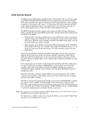
... SAS_Key connector that is located at boot, but the SAS controller is placed on the Advanced | Mass Storage setup page to enable or disable the SAS option ROM and the SAS controller. Both of these options must be enabled to function as either or both SAS and SATA hard disk drives. For information on the server board continue to use either SAS or SATA ports and the two black ports on the server board. Intel® Server Board S5000VSA User's Guide 5
... SAS_Key connector that is located at boot, but the SAS controller is placed on the Advanced | Mass Storage setup page to enable or disable the SAS option ROM and the SAS controller. Both of these options must be enabled to function as either or both SAS and SATA hard disk drives. For information on the server board continue to use either SAS or SATA ports and the two black ports on the server board. Intel® Server Board S5000VSA User's Guide 5
User Guide
Page 25
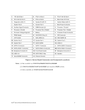
.... Intel® Server Board S5000VSA User's Guide 7 Auxiliary Signal Connector P. Backplane Connector B QQ. DIMM Sockets (2) Q. Processor Power Connector X. Backplane Connector A SS. PCI-X 64/100 Slot 5 G. IPMB Header Y. SATA 3/SAS 1 Connector NN. PCIe* x4 Slot 3 E. SAS RAID 5 Key (3) Z. SATA 1 Connector LL. SATA 5/SAS 3 Connector PP. SATA 4/SAS 2 Connector OO. PCI-X* 64/133 Slot 4 F. Back Panel I/O Ports I. System Fan 2 GG. USB 4-5 JJ. Speaker Figure 2. A. SATA RAID 5 Key UU. Processor 1 Socket R. Processor 2 Socket S. LCP Header BB...
.... Intel® Server Board S5000VSA User's Guide 7 Auxiliary Signal Connector P. Backplane Connector B QQ. DIMM Sockets (2) Q. Processor Power Connector X. Backplane Connector A SS. PCI-X 64/100 Slot 5 G. IPMB Header Y. SATA 3/SAS 1 Connector NN. PCIe* x4 Slot 3 E. SAS RAID 5 Key (3) Z. SATA 1 Connector LL. SATA 5/SAS 3 Connector PP. SATA 4/SAS 2 Connector OO. PCI-X* 64/133 Slot 4 F. Back Panel I/O Ports I. System Fan 2 GG. USB 4-5 JJ. Speaker Figure 2. A. SATA RAID 5 Key UU. Processor 1 Socket R. Processor 2 Socket S. LCP Header BB...
User Guide
Page 28
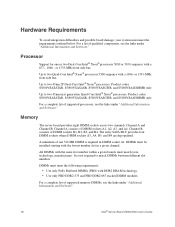
... must be installed starting with the lowest number slot in DIMM socket A1. All DIMMs with a 1066- or 1333-MHz front side bus. Product codes S5000VSASATAR, S5000VSASASR, S5000VSASCSIR, and S5000VSA4DIMMR only. Up to two 45nm 2P Dual-Core Intel® Xeon® processors. Memory The server board provides eight DIMM sockets across two channels, Channel A and Channel B. Channel A consists of DIMM sockets B1, B2, B3, and B4. Processor Support for one...
... must be installed starting with the lowest number slot in DIMM socket A1. All DIMMs with a 1066- or 1333-MHz front side bus. Product codes S5000VSASATAR, S5000VSASASR, S5000VSASCSIR, and S5000VSA4DIMMR only. Up to two 45nm 2P Dual-Core Intel® Xeon® processors. Memory The server board provides eight DIMM sockets across two channels, Channel A and Channel B. Channel A consists of DIMM sockets B1, B2, B3, and B4. Processor Support for one...

User Guide
Page 29
... controls and indicators beyond the standard control panel. Optional Hardware Hard Disk Drives The server board supports different hard disk drive options, depending on the version of the server board purchased. • The Intel® Server Board S5000VSASATA/S5000VSASATAR provides six SATA ports and one or two ATA-133 devices. IDE devices can be connected to the standard IDE connector located near the front left side of the server board. See the documentation included with your server chassis for additional drive information and drive installation instructions. Your supply...
... controls and indicators beyond the standard control panel. Optional Hardware Hard Disk Drives The server board supports different hard disk drive options, depending on the version of the server board purchased. • The Intel® Server Board S5000VSASATA/S5000VSASATAR provides six SATA ports and one or two ATA-133 devices. IDE devices can be connected to the standard IDE connector located near the front left side of the server board. See the documentation included with your server chassis for additional drive information and drive installation instructions. Your supply...

User Guide
Page 31
... Power On Self Test (POST), you will see this condition, the BIOS will find details about specific BIOS setup screens. These parameters can enter and start BIOS Setup under several conditions: • When you turn on the server, after POST completes the memory test. • When you are provided only to boot. See "Additional Information and Software" for a link to change server configuration defaults. For instructions on the server board to clear the CMOS memory. Setup Menus Each BIOS Setup menu...
... Power On Self Test (POST), you will see this condition, the BIOS will find details about specific BIOS setup screens. These parameters can enter and start BIOS Setup under several conditions: • When you turn on the server, after POST completes the memory test. • When you are provided only to boot. See "Additional Information and Software" for a link to change server configuration defaults. For instructions on the server board to clear the CMOS memory. Setup Menus Each BIOS Setup menu...
User Guide
Page 43
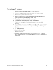
... server board. 6. Remove the server's cover. "Intel® Server Board S5000VSA User's Guide" 25 Lift the processor lever. 10. Otherwise, install the protective socket cover over the empty processor socket and reinstall the chassis cover. Turn off all peripheral devices connected to break the seal between the heat sink and the processor. 8. Raise the CPU load plate. 11. Unplug the processor fan cable from the server. 4. Turn off the server. 3. See the documentation that came with your server chassis for instructions...
... server board. 6. Remove the server's cover. "Intel® Server Board S5000VSA User's Guide" 25 Lift the processor lever. 10. Otherwise, install the protective socket cover over the empty processor socket and reinstall the chassis cover. Turn off all peripheral devices connected to break the seal between the heat sink and the processor. 8. Raise the CPU load plate. 11. Unplug the processor fan cable from the server. 4. Turn off the server. 3. See the documentation that came with your server chassis for instructions...
User Guide
Page 59
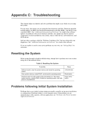
... installation or configuration. For any drivers used for BIOS, the baseboard management controller (BMC), and the hot-swap controller (HSC). See "Additional Information and Software" for a link to this Soft boot reset to resolve your server problems on your system, such as video drivers, network drivers, and SCSI drivers. Resetting the System Before going through in your own, see "Problems with your system using the latest firmware and files. Table 6. Turn the system power...
... installation or configuration. For any drivers used for BIOS, the baseboard management controller (BMC), and the hot-swap controller (HSC). See "Additional Information and Software" for a link to this Soft boot reset to resolve your server problems on your system, such as video drivers, network drivers, and SCSI drivers. Resetting the System Before going through in your own, see "Problems with your system using the latest firmware and files. Table 6. Turn the system power...

User Guide
Page 60
... jumper and switch settings on add-in Setup correct? • Is the operating system properly loaded? First Steps Checklist • Is AC power available at the AC source. • Are all cables correctly connected and secured? • Are the processors fully seated in their slots on the server board? • Are all jumper settings on the server board correct? • Are all device drivers properly installed? • Are the configuration settings...
... jumper and switch settings on add-in Setup correct? • Is the operating system properly loaded? First Steps Checklist • Is AC power available at the AC source. • Are all cables correctly connected and secured? • Are the processors fully seated in their slots on the server board? • Are all jumper settings on the server board correct? • Are all device drivers properly installed? • Are the configuration settings...
User Guide
Page 62
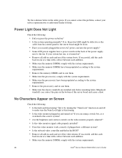
... the chassis standoffs are using a switch box, is it turned on button? • Is the system operating normally? Misplaced standoffs can contact the pins on the video monitor properly adjusted? • Is the video monitor signal cable properly installed? • Does this video monitor work correctly if plugged into a different system? • Is the onboard video controller enabled in the BIOS? • Remove all add-in the order given. If so, the power LED...
... the chassis standoffs are using a switch box, is it turned on button? • Is the system operating normally? Misplaced standoffs can contact the pins on the video monitor properly adjusted? • Is the video monitor signal cable properly installed? • Does this video monitor work correctly if plugged into a different system? • Is the onboard video controller enabled in the BIOS? • Remove all add-in the order given. If so, the power LED...

User Guide
Page 64
... are not shared with your PCI card(s) for the same duplex mode as the network controller. • Make sure the correct networking software is configured for information on the drive set correctly? • Is the drive properly configured? CD-ROM Drive or DVD-ROM Drive Activity Light Does Not Light Check the following: • Are the CD-ROM/DVD-ROM drive's power and signal cables properly installed? • Are all relevant switches and jumpers on changing interrupts. 46 Intel® Server Board S5000VSA User's Guide
... are not shared with your PCI card(s) for the same duplex mode as the network controller. • Make sure the correct networking software is configured for information on the drive set correctly? • Is the drive properly configured? CD-ROM Drive or DVD-ROM Drive Activity Light Does Not Light Check the following: • Are the CD-ROM/DVD-ROM drive's power and signal cables properly installed? • Are all relevant switches and jumpers on changing interrupts. 46 Intel® Server Board S5000VSA User's Guide

User Guide
Page 65
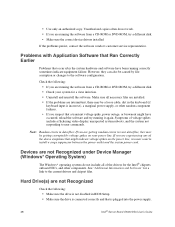
... file. • The controller stopped working without apparent cause • Re-seat the adapter. • Put the adapter in a different slot. • The network driver files may be corrupt or deleted. Problems with the AC power cord plugged in, a signal may be sent to command the system to the port from the server. Faulty equipment is properly installed and configured for the software. See the software...
... file. • The controller stopped working without apparent cause • Re-seat the adapter. • Put the adapter in a different slot. • The network driver files may be corrupt or deleted. Problems with the AC power cord plugged in, a signal may be sent to command the system to the port from the server. Faulty equipment is properly installed and configured for the software. See the software...
User Guide
Page 66
... Problems that a transient voltage spike, power outage, or brownout might indicate voltage spikes on your system for a link to the software configuration. Symptoms of the above symptoms that is plugged into the power supply. 48 Intel® Server Board S5000VSA User's Guide • Use only an authorized copy. Unauthorized copies often do not include all necessary files are installed. • If the problems are running the software from a CD-ROM or DVD-ROM...
... Problems that a transient voltage spike, power outage, or brownout might indicate voltage spikes on your system for a link to the software configuration. Symptoms of the above symptoms that is plugged into the power supply. 48 Intel® Server Board S5000VSA User's Guide • Use only an authorized copy. Unauthorized copies often do not include all necessary files are installed. • If the problems are running the software from a CD-ROM or DVD-ROM...

User Guide
Page 67
... power budget for a link to software to be the first bootable device. LED Information The Intel® Server Board S5000VSA includes LEDs that each SCSI ID number is listed below. Table 7. Bootable CD-ROM Disk Is Not Detected Check the following: • Make sure the BIOS is configured to allow the CD-ROM to check your drives. • If using a RAID configuration with a description of these LEDs with SCSI or SATA drives...
... power budget for a link to software to be the first bootable device. LED Information The Intel® Server Board S5000VSA includes LEDs that each SCSI ID number is listed below. Table 7. Bootable CD-ROM Disk Is Not Detected Check the following: • Make sure the BIOS is configured to allow the CD-ROM to check your drives. • If using a RAID configuration with a description of these LEDs with SCSI or SATA drives...


