

Technical Product Specification
Page 6
... Management Headers...64 6.2.1 Intel® Remote Management Module 4 (Intel® RMM4) Lite Connector 64 6.2.2 IPMB Header...64 6.2.3 Control Panel Connector ...64 6.3 Bridge Board Connector...65 6.3.1 Power Button ...66 6.3.2 Reset Button...67 6.4 I/O Connectors ...67 6.4.1 PCI Express* Connectors...67 6.4.2 VGA Connector...77 6.4.3 NIC Connectors ...78 6.4.4 SATA Connectors ...78 6.4.5 SATA SGPIO Connectors...79 6.4.6 Hard Drive Activity (Input) LED Header 79 6.4.7 Intel® RAID C600 Upgrade Key Connector 79 6.4.8 Serial Port Connectors ...80 6.4.9 USB Connectors...
... Management Headers...64 6.2.1 Intel® Remote Management Module 4 (Intel® RMM4) Lite Connector 64 6.2.2 IPMB Header...64 6.2.3 Control Panel Connector ...64 6.3 Bridge Board Connector...65 6.3.1 Power Button ...66 6.3.2 Reset Button...67 6.4 I/O Connectors ...67 6.4.1 PCI Express* Connectors...67 6.4.2 VGA Connector...77 6.4.3 NIC Connectors ...78 6.4.4 SATA Connectors ...78 6.4.5 SATA SGPIO Connectors...79 6.4.6 Hard Drive Activity (Input) LED Header 79 6.4.7 Intel® RAID C600 Upgrade Key Connector 79 6.4.8 Serial Port Connectors ...80 6.4.9 USB Connectors...

Technical Product Specification
Page 12
.... BIOS Default Jumper...90 Table 55. InfiniBand* Link/Activity LED ...96 Table 59. Intel® Remote Management Module 4 (RMM4) Options 127 Table 65. Minimum Load Ratings ...141 Table 70. Compute Module Fan Connector...83 Table 47. BIOS Recovery Mode Jumper (J7A7 89 Table 54. Fan Profile Mapping...121 Table 63. Air Flow ...135 Table 67. Internal USB Connector ...80 Table 40. BMC Boot/Reset Status LED Indicators 95 Table 58. Processor Sensors...109 Table 61. Power Supply DC Power...
.... BIOS Default Jumper...90 Table 55. InfiniBand* Link/Activity LED ...96 Table 59. Intel® Remote Management Module 4 (RMM4) Options 127 Table 65. Minimum Load Ratings ...141 Table 70. Compute Module Fan Connector...83 Table 47. BIOS Recovery Mode Jumper (J7A7 89 Table 54. Fan Profile Mapping...121 Table 63. Air Flow ...135 Table 67. Internal USB Connector ...80 Table 40. BMC Boot/Reset Status LED Indicators 95 Table 58. Processor Sensors...109 Table 61. Power Supply DC Power...

Technical Product Specification
Page 19
... Upgrade Key to enable SATA RAID 5 Onboard Emulex* Pilot III* Controller Support for Intel® Remote Management Module 4 Lite solutions Intel® Light-Guided Diagnostics on the server board is designed for Intel® Intelligent Power Node Manager (Need PMBus*-compliant power supply) Warning! include Intel® Server Board S2600TP HNS2600TPF - The riser slot 1 on field replaceable units Support for Intel® System Management Software Support for plugging in the PCIe* card may cause permanent server board and PCIe* card...
... Upgrade Key to enable SATA RAID 5 Onboard Emulex* Pilot III* Controller Support for Intel® Remote Management Module 4 Lite solutions Intel® Light-Guided Diagnostics on the server board is designed for Intel® Intelligent Power Node Manager (Need PMBus*-compliant power supply) Warning! include Intel® Server Board S2600TP HNS2600TPF - The riser slot 1 on field replaceable units Support for Intel® System Management Software Support for plugging in the PCIe* card may cause permanent server board and PCIe* card...
Technical Product Specification
Page 39
... a given operating system. The following instructional message is displayed unconditionally. The BIOS image can be updated using a standalone IFLASH32 utility in the order previously defined by the system. When the Setup Utility is entered, the Main screen is purely a Text Mode screen, as the boot order in the event a serious error occurs during POST. Technical Product Specification Product Features Overview system configuration information. However, in the BIOS setup. If a User password is...
... a given operating system. The following instructional message is displayed unconditionally. The BIOS image can be updated using a standalone IFLASH32 utility in the order previously defined by the system. When the Setup Utility is entered, the Main screen is purely a Text Mode screen, as the boot order in the event a serious error occurs during POST. Technical Product Specification Product Features Overview system configuration information. However, in the BIOS setup. If a User password is...

Technical Product Specification
Page 40
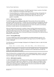
... SDR updates or provide other user input to its default position and the system is switched back to the system when any video or console is included here for example, could be necessary to the Error Manager Page in the BIOS Setup utility. The system boots to the embedded uEFI shell, and a "Recovery Complete" event is logged to monitor the appropriate sensor data and operate the system with Recovery Mode. The...
... SDR updates or provide other user input to its default position and the system is switched back to the system when any video or console is included here for example, could be necessary to the Error Manager Page in the BIOS Setup utility. The system boots to the embedded uEFI shell, and a "Recovery Complete" event is logged to monitor the appropriate sensor data and operate the system with Recovery Mode. The...
Technical Product Specification
Page 44
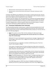
... processor specification updates published by Intel Corporation. 3.4 Processor Initialization Error Summary The following message: "Unrecoverable fatal error found. This operation will occur regardless of processor cache memory. The System Status LED will halt and display the following table describes mixed processor conditions and recommended actions for all Fatal Errors that all installed processors can be logged to a steady Amber color for all levels of whether the BIOS Setup option "Post Error Pause" is set to Enable...
... processor specification updates published by Intel Corporation. 3.4 Processor Initialization Error Summary The following message: "Unrecoverable fatal error found. This operation will occur regardless of processor cache memory. The System Status LED will halt and display the following table describes mixed processor conditions and recommended actions for all Fatal Errors that all installed processors can be logged to a steady Amber color for all levels of whether the BIOS Setup option "Post Error Pause" is set to Enable...
Technical Product Specification
Page 53
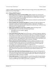
... with address and command in "write cycle" and unscrambles the data in "read transaction. Patrol scrubbing proactively searches the system memory, repairing correctable errors. The mirrored copy of the memory is stored in any portion of a single DRAM device on a read cycle". Dynamic (without reboot) failover to the mirrored DIMMs is enabled. Failed DIMM Isolation: The ability to identify a specific failing DIMM, thereby enabling the user to replace...
... with address and command in "write cycle" and unscrambles the data in "read transaction. Patrol scrubbing proactively searches the system memory, repairing correctable errors. The mirrored copy of the memory is stored in any portion of a single DRAM device on a read cycle". Dynamic (without reboot) failover to the mirrored DIMMs is enabled. Failed DIMM Isolation: The ability to identify a specific failing DIMM, thereby enabling the user to replace...

Technical Product Specification
Page 54
... memory subsystem support (such as Memory RAS and Error Management) in the BIOS setup is applied commonly across processor sockets. All DIMMs must be installed without populating the associated memory slots provided a second processor is not populated. A processor may be DDR4 DIMMs. 40 Revision 1.0 DDR4 DIMM Support Guidelines Type RDIMM RDIMM RDIMM RDIMM LRDIMM Ranks Per DIMM and Data Width SRx4 SRx8 DRx8 DRx4 QRx4 DIMM Capacity (GB) Speed (MT/s); DIMM...
... memory subsystem support (such as Memory RAS and Error Management) in the BIOS setup is applied commonly across processor sockets. All DIMMs must be installed without populating the associated memory slots provided a second processor is not populated. A processor may be DDR4 DIMMs. 40 Revision 1.0 DDR4 DIMM Support Guidelines Type RDIMM RDIMM RDIMM RDIMM LRDIMM Ranks Per DIMM and Data Width SRx4 SRx8 DRx8 DRx4 QRx4 DIMM Capacity (GB) Speed (MT/s); DIMM...

Technical Product Specification
Page 58
... boot with a beep code and a memory error code to be displayed via the POST Code Diagnostic LEDs. Less fatal errors will cause a System Halt with data integrity will cause a POST Error Code to be generated as a Major Error. Memory Support Technical Product Specification If Quiet Boot is disabled, the BIOS displays the total system memory on the diagnostic screen at the beginning of POST includes multiple functions, including: DIMM discovery Channel training DIMM population validation check Memory controller...
... boot with a beep code and a memory error code to be displayed via the POST Code Diagnostic LEDs. Less fatal errors will cause a System Halt with data integrity will cause a POST Error Code to be generated as a Major Error. Memory Support Technical Product Specification If Quiet Boot is disabled, the BIOS displays the total system memory on the diagnostic screen at the beginning of POST includes multiple functions, including: DIMM discovery Channel training DIMM population validation check Memory controller...

Technical Product Specification
Page 63
... of PCI devices with PCI-PCI bridges. The NTB port on another subsystem. Legacy code cannot make any assumption about the scan order of devices or the order in the BIOS boot process, and never change during the pre-boot phase. The bus assignments occur once, early in which resources are assigned numbers. PCI bus number assignments may vary from the remote host memory domain while enabling status and data exchange...
... of PCI devices with PCI-PCI bridges. The NTB port on another subsystem. Legacy code cannot make any assumption about the scan order of devices or the order in the BIOS boot process, and never change during the pre-boot phase. The bus assignments occur once, early in which resources are assigned numbers. PCI bus number assignments may vary from the remote host memory domain while enabling status and data exchange...

Technical Product Specification
Page 69
...; Software RAID with system providing memory and CPU utilization RAID Level 0 - Technical Product Specification Server Board I /O rates can be loaded for selection in the boot order At each boot up to six drives, enabling higher throughput for applications that require both performance and fault-tolerance. RAID 5 is well suited for data intensive applications such as NTLDR) and by hitting the keys during system POST. Provides boot support when using Intel®...
...; Software RAID with system providing memory and CPU utilization RAID Level 0 - Technical Product Specification Server Board I /O rates can be loaded for selection in the boot order At each boot up to six drives, enabling higher throughput for applications that require both performance and fault-tolerance. RAID 5 is well suited for data intensive applications such as NTLDR) and by hitting the keys during system POST. Provides boot support when using Intel®...
Technical Product Specification
Page 102
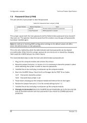
... either the Administrator or User passwords. Strongly recommended: Boot into the BIOS Setup. Note: No method of Operation Normal Clear Password Note Normal mode, password in and power up the compute module. 4. Check the Error Manager tab for POST Error Codes: 5221 Passwords cleared by which the Administrator and User passwords can only be cleared if they were set 5. Table 52. Password Clear Jumper (J7A6) Jumper Position 1-2 2-3 Mode of resetting BIOS configuration settings to clear the passwords. 3. It is set . Boot into the BIOS Setup immediately, go to the...
... either the Administrator or User passwords. Strongly recommended: Boot into the BIOS Setup. Note: No method of Operation Normal Clear Password Note Normal mode, password in and power up the compute module. 4. Check the Error Manager tab for POST Error Codes: 5221 Passwords cleared by which the Administrator and User passwords can only be cleared if they were set 5. Table 52. Password Clear Jumper (J7A6) Jumper Position 1-2 2-3 Mode of resetting BIOS configuration settings to clear the passwords. 3. It is set . Boot into the BIOS Setup immediately, go to the...

Technical Product Specification
Page 104
... rebooting. 3. A normal BIOS update can be used. Power on the compute module. 6. Move the jumper from the chassis. 10. Boot the system into the EFI shell directly, the BIOS recovery is not necessary to the BIOS defaults are reset to factory default This jumper causes the BIOS Setup settings to be reset to pins 2-3 momentarily. Configuration Jumpers Technical Product Specification 2. BIOS Default Jumper Jumper Position 1-2 2-3 Mode of NVRAM variable storage, and then load the BIOS default settings. Note that this jumper according to as "Clear CMOS", or "Clear NVRAM...
... rebooting. 3. A normal BIOS update can be used. Power on the compute module. 6. Move the jumper from the chassis. 10. Boot the system into the EFI shell directly, the BIOS recovery is not necessary to the BIOS defaults are reset to factory default This jumper causes the BIOS Setup settings to be reset to pins 2-3 momentarily. Configuration Jumpers Technical Product Specification 2. BIOS Default Jumper Jumper Position 1-2 2-3 Mode of NVRAM variable storage, and then load the BIOS default settings. Note that this jumper according to as "Clear CMOS", or "Clear NVRAM...
Technical Product Specification
Page 127
... BMC supports redundant fan monitoring and implements fan redundancy sensors for each hot swappable fan. A fan redundancy sensor generates events when its associated set sufficiently low as manual re-arm sensors because a lower-critical threshold crossing can be configured on and operating normally. Most fan implementations provide for fan presence upon changes in turn may cause a failing fan's speed to be large. Events are only logged for a variable speed fan, so the variations in fan...
... BMC supports redundant fan monitoring and implements fan redundancy sensors for each hot swappable fan. A fan redundancy sensor generates events when its associated set sufficiently low as manual re-arm sensors because a lower-critical threshold crossing can be configured on and operating normally. Most fan implementations provide for fan presence upon changes in turn may cause a failing fan's speed to be large. Events are only logged for a variable speed fan, so the variations in fan...

Technical Product Specification
Page 128
... detects fan failure and may cause a failing fan's speed to rise above the "fault" threshold and can result in boosting of the IPMI sensor if a fan failure is a BMC command and BIOS setup option to enable/disable this scenario, the fan power is associated with a fan presence sensor for the domain to result in the IPMI sensor shall be cleared and a de-assertion event shall be long enough to 0. By default...
... detects fan failure and may cause a failing fan's speed to rise above the "fault" threshold and can result in boosting of the IPMI sensor if a fan failure is a BMC command and BIOS setup option to enable/disable this scenario, the fan power is associated with a fan presence sensor for the domain to result in the IPMI sensor shall be cleared and a de-assertion event shall be long enough to 0. By default...

Technical Product Specification
Page 144
..., reference the Intel® Remote Management Module 4 and Integrated BMC Web Console Users Guide. 9.5.3 Advanced Management Feature Support (RMM4 Lite) The integrated baseboard management controller has support for management traffic; Remote access and control software runs in the integrated baseboard management controller, utilizing expanded capabilities enabled by the user. Server Power Control - Once mounted, the remote device appears just like a local device to the server allowing system administrators or users to force into Setup on a reset System POST results...
..., reference the Intel® Remote Management Module 4 and Integrated BMC Web Console Users Guide. 9.5.3 Advanced Management Feature Support (RMM4 Lite) The integrated baseboard management controller has support for management traffic; Remote access and control software runs in the integrated baseboard management controller, utilizing expanded capabilities enabled by the user. Server Power Control - Once mounted, the remote device appears just like a local device to the server allowing system administrators or users to force into Setup on a reset System POST results...
Technical Product Specification
Page 150
... Management Technical Product Specification The installation and functionality of several components are documented in the configuration matrix found in the Intel® Server Board S2600TP product family Power Budget and Thermal Configuration Tool, available as a download online at http://www.intel.com/support. The CPU-1 processor + CPU heat sink must be impacted when operating within supported maximum thermal limits, the compute module must meet the following operating and configuration guidelines: The compute module operating...
... Management Technical Product Specification The installation and functionality of several components are documented in the configuration matrix found in the Intel® Server Board S2600TP product family Power Budget and Thermal Configuration Tool, available as a download online at http://www.intel.com/support. The CPU-1 processor + CPU heat sink must be impacted when operating within supported maximum thermal limits, the compute module must meet the following operating and configuration guidelines: The compute module operating...

Technical Product Specification
Page 196
... Board Location U5B2 U2D2 U5M1 U5A2 U4B1 User Data No (FW) No (BIOS) No No No Name Firmware Flash BIOS Flash Connect-IB Flash NIC EEPROM FW SDRAM Component Type Three types of Volatility This Appendix describes the volatile and non-volatile components on the Intel® Server Board S2600TP Product Family. Some areas are required for the Intel® Server Board S2600TP is powered by the specific component. Non-Volatile memory must be used to volatile memory...
... Board Location U5B2 U2D2 U5M1 U5A2 U4B1 User Data No (FW) No (BIOS) No No No Name Firmware Flash BIOS Flash Connect-IB Flash NIC EEPROM FW SDRAM Component Type Three types of Volatility This Appendix describes the volatile and non-volatile components on the Intel® Server Board S2600TP Product Family. Some areas are required for the Intel® Server Board S2600TP is powered by the specific component. Non-Volatile memory must be used to volatile memory...
System Integration and Service Guide
Page 10
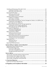
... Removing the Power Docking Board 44 Installing the Power Docking Board 44 Replacing the Fan ...45 Removing the Fan ...45 Installing the Fan ...45 Replacing the Backup Battery ...46 System Software Updates and Configuration 48 Updating the System Software Stack ...48 Using the BIOS Setup Utility ...48 Entering the BIOS Setup ...48 No Access to the BIOS Setup Utility 49 Navigating the BIOS Setup Utility ...49 Server Utilities ...52 Intel® System Information Retrieve Utility (sysinfo 52 Intel® One Boot Flash Update Utility (OFU 52 Intel® System Event Log (SEL) Viewer Utility...
... Removing the Power Docking Board 44 Installing the Power Docking Board 44 Replacing the Fan ...45 Removing the Fan ...45 Installing the Fan ...45 Replacing the Backup Battery ...46 System Software Updates and Configuration 48 Updating the System Software Stack ...48 Using the BIOS Setup Utility ...48 Entering the BIOS Setup ...48 No Access to the BIOS Setup Utility 49 Navigating the BIOS Setup Utility ...49 Server Utilities ...52 Intel® System Information Retrieve Utility (sysinfo 52 Intel® One Boot Flash Update Utility (OFU 52 Intel® System Event Log (SEL) Viewer Utility...
System Integration and Service Guide
Page 66
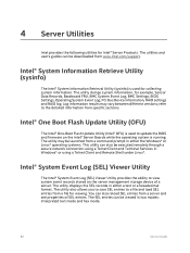
... through a secure network connection using a Telnet Client and Remote Shell under Linux*. You can be viewed in Windows* or using a Telnet Client and Terminal Services in two modes: interpreted text mode and hex mode. 52 Service Guide The utility dumps system information, for Intel® Server Products. 4 Server Utilities Intel provides the following utilities for example, Sensor Data Records, Baseboard FRU, BMC System Event Log, BMC Settings, BIOS Settings, Operating System Event Log, PCI Bus Device Information, RAID settings and RAID log. Log information results may...
... through a secure network connection using a Telnet Client and Remote Shell under Linux*. You can be viewed in Windows* or using a Telnet Client and Terminal Services in two modes: interpreted text mode and hex mode. 52 Service Guide The utility dumps system information, for Intel® Server Products. 4 Server Utilities Intel provides the following utilities for example, Sensor Data Records, Baseboard FRU, BMC System Event Log, BMC Settings, BIOS Settings, Operating System Event Log, PCI Bus Device Information, RAID settings and RAID log. Log information results may...


