
Data Sheet
Page 18
... outputs may interfere with some TAP functions, complicate debug probing, and prevent boundary scan testing. For optimum noise margin, all RESERVED lands. For details, see Table 2-6 for proper Boundary Scan testing of the same value as GTL+ termination is 50 Ω, then a value between... a single pull-up resistor which matches the nominal trace impedance. Note that do not include on the processor silicon. A matched resistor must be individually connected to power or ground, a resistor will also allow signals to be used outputs must remain unconnected. For example,...
... outputs may interfere with some TAP functions, complicate debug probing, and prevent boundary scan testing. For optimum noise margin, all RESERVED lands. For details, see Table 2-6 for proper Boundary Scan testing of the same value as GTL+ termination is 50 Ω, then a value between... a single pull-up resistor which matches the nominal trace impedance. Note that do not include on the processor silicon. A matched resistor must be individually connected to power or ground, a resistor will also allow signals to be used outputs must remain unconnected. For example,...

Data Sheet
Page 22
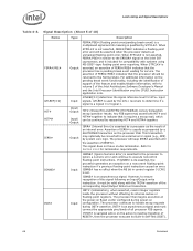
...specification is based on design characterization and is the maximum total current drawn from the VTT plane by the system. This is not tested. 10. Adherence to the voltage specifications for details. 7. Baseboard bandwidth is not coupled into the oscilloscope probe. 5. This parameter is... on VCC_MAX loadline. Refer to determine the total ITT drawn by only the processor. Refer to the Voltage Regulator Design Guide to Figure 2-1 for the processor are required to 20 MHz. 9. The processor should be connected to VCC. The maximum length of ground wire on -board...
...specification is based on design characterization and is the maximum total current drawn from the VTT plane by the system. This is not tested. 10. Adherence to the voltage specifications for details. 7. Baseboard bandwidth is not coupled into the oscilloscope probe. 5. This parameter is... on VCC_MAX loadline. Refer to determine the total ITT drawn by only the processor. Refer to the Voltage Regulator Design Guide to Figure 2-1 for the processor are required to 20 MHz. 9. The processor should be connected to VCC. The maximum length of ground wire on -board...

Data Sheet
Page 39
...to the IHS surface. 3. These guidelines are based on limited testing for the processor package. A thermal and mechanical solution design must also provide the minimum specified load on the processor package. 3. Table 3-1. Package Loading Specifications Table 3-1 provides dynamic ... specifications for design characterization. Also, any thermal and mechanical solutions. Processor Loading Specifications Parameter Minimum Static Dynamic 80 N [17 lbf] - These specifications are based on limited testing for thermal and mechanical solution. Loading limits are typically mounted to ...
...to the IHS surface. 3. These guidelines are based on limited testing for the processor package. A thermal and mechanical solution design must also provide the minimum specified load on the processor package. 3. Table 3-1. Package Loading Specifications Table 3-1 provides dynamic ... specifications for design characterization. Also, any thermal and mechanical solutions. Processor Loading Specifications Parameter Minimum Static Dynamic 80 N [17 lbf] - These specifications are based on limited testing for thermal and mechanical solution. Loading limits are typically mounted to ...
Data Sheet
Page 68
...core logic. This transaction may assert both HIT# and HITM# together to indicate that it must connect the appropriate pins/lands of FERR#/PBE# indicates that the processor... converted to ensure recognition of the Intel Architecture Software Developer's Manual and the Intel Processor Identification and the CPUID Instruction application...NE bit in Self-Test (BIST). 68 Datasheet The processor then begins execution at the power-on Reset vector ...processor has a pending break event waiting for GTL+ input signals. The assertion of RESET#, then the processor executes its internal caches...
...core logic. This transaction may assert both HIT# and HITM# together to indicate that it must connect the appropriate pins/lands of FERR#/PBE# indicates that the processor... converted to ensure recognition of the Intel Architecture Software Developer's Manual and the Intel Processor Identification and the CPUID Instruction application...NE bit in Self-Test (BIST). 68 Datasheet The processor then begins execution at the power-on Reset vector ...processor has a pending break event waiting for GTL+ input signals. The assertion of RESET#, then the processor executes its internal caches...

Data Sheet
Page 71
... support. TDO connects to enter a low power Stop-Grant state. See Section 2.4 for the processor Test Bus (also known as the Test Access Port). On accepting a System Management Interrupt, the processor saves the current state and enter System Management Mode (SMM). STPCLK# (Stop Clock), when asserted, causes the processor to core 1. TCK (Test Clock) provides the clock input for...
... support. TDO connects to enter a low power Stop-Grant state. See Section 2.4 for the processor Test Bus (also known as the Test Access Port). On accepting a System Management Interrupt, the processor saves the current state and enter System Management Mode (SMM). STPCLK# (Stop Clock), when asserted, causes the processor to core 1. TCK (Test Clock) provides the clock input for...

Data Sheet
Page 72
...asserted) and is ready to processor core power (VCC). Upon assertion of THERMTRIP#, the processor will shut off its core voltage (VCC) must be driven low during power on previous generation processors. VCC are valid). VCCIOPLL provides isolated power for internal processor FSB PLLs on Reset. ... deasserted. VCCA provides isolated power for VCC. To protect the processor, its internal clocks (thus, halting program execution) in the Voltage Regulator-Down (VRD) 11.0 Processor Power Delivery Design Guidelines For Desktop LGA775 Socket. 72 Datasheet TMS (Test Mode Select) is provided ...
...asserted) and is ready to processor core power (VCC). Upon assertion of THERMTRIP#, the processor will shut off its core voltage (VCC) must be driven low during power on previous generation processors. VCC are valid). VCCIOPLL provides isolated power for internal processor FSB PLLs on Reset. ... deasserted. VCCA provides isolated power for VCC. To protect the processor, its internal clocks (thus, halting program execution) in the Voltage Regulator-Down (VRD) 11.0 Processor Power Delivery Design Guidelines For Desktop LGA775 Socket. 72 Datasheet TMS (Test Mode Select) is provided ...
Data Sheet
Page 75
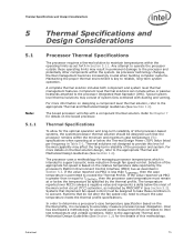
.... Systems that correlates to Intel test temperature and voltage conditions. Typical system level thermal solutions may affect the long-term reliability of system fans combined with a component thermal solution. Refer to Chapter 7 for managing processor temperatures which is based on...management becomes increasingly crucial when building computer systems. Maintaining the proper thermal environment is necessary to accurately measure processor power dissipation. A complete thermal solution includes both component and system level thermal management features. Thermal solutions not...
.... Systems that correlates to Intel test temperature and voltage conditions. Typical system level thermal solutions may affect the long-term reliability of system fans combined with a component thermal solution. Refer to Chapter 7 for managing processor temperatures which is based on...management becomes increasingly crucial when building computer systems. Maintaining the proper thermal environment is necessary to accurately measure processor power dissipation. A complete thermal solution includes both component and system level thermal management features. Thermal solutions not...
Data Sheet
Page 76
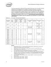
...66 95 12 - Q9400 2.66 95 12 8 Q9300 2.50 95 12 - Specification is ensured by design characterization and not 100% tested. 2. These processors have a lower TDP...tested. 3. This table shows the maximum TDP for processor thermal solution design targets. Individual processors may have CPUID = 1067Ah. 7. Refer to consume maximum power dissipation for a sustained periods of time. These processors have CPUID = 10677h. 8. Processor Thermal Specifications Processor Number Core Freq. (GHz) Thermal Design Power (W) 3, 4 Extended HALT Power (W)1 Deeper Sleep Power...
...66 95 12 - Q9400 2.66 95 12 8 Q9300 2.50 95 12 - Specification is ensured by design characterization and not 100% tested. 2. These processors have a lower TDP...tested. 3. This table shows the maximum TDP for processor thermal solution design targets. Individual processors may have CPUID = 1067Ah. 7. Refer to consume maximum power dissipation for a sustained periods of time. These processors have CPUID = 10677h. 8. Processor Thermal Specifications Processor Number Core Freq. (GHz) Thermal Design Power (W) 3, 4 Extended HALT Power (W)1 Deeper Sleep Power...
Design Guidelines
Page 4
...Testing 49 5.3.1 5.3.2 5.3.3 Structural Reliability Testing 49 5.3.1.1 Random Vibration Test Procedure 49 5.3.1.2 Shock Test Procedure 49 5.3.1.2.1 Recommended Test Sequence 50 5.3.1.2.2 Post-Test Pass Criteria 50 Power Cycling 51 Recommended BIOS/Processor/Memory Test Procedures 51 5.4 Material and Recycling Requirements 51 5.5 Safety Requirements 52 5.6 Geometric Envelope for Intel...of Intel® Quiet System Technology .......60 6.3 Intel® QST Configuration and Tuning 62 6.4 Fan Hub Thermistor and Intel® QST 62 LGA775 Socket Heatsink Loading 63 A.1 LGA775 Socket ...
...Testing 49 5.3.1 5.3.2 5.3.3 Structural Reliability Testing 49 5.3.1.1 Random Vibration Test Procedure 49 5.3.1.2 Shock Test Procedure 49 5.3.1.2.1 Recommended Test Sequence 50 5.3.1.2.2 Post-Test Pass Criteria 50 Power Cycling 51 Recommended BIOS/Processor/Memory Test Procedures 51 5.4 Material and Recycling Requirements 51 5.5 Safety Requirements 52 5.6 Geometric Envelope for Intel...of Intel® Quiet System Technology .......60 6.3 Intel® QST Configuration and Tuning 62 6.4 Fan Hub Thermistor and Intel® QST 62 LGA775 Socket Heatsink Loading 63 A.1 LGA775 Socket ...

Design Guidelines
Page 5
... Line Management 75 C.2 Interface Material Area 75 C.3 Interface Material Performance 75 Case Temperature Reference Metrology 77 D.1 Objective and Scope 77 D.2 Supporting Test Equipment 77 D.3 Thermal calibration and controls 78 D.4 IHS Groove 79 D.5 Thermocouple Attach Procedure 84 D.5.1 D.5.2 D.5.3 D.5.4 Thermocouple Conditioning and Preparation ... 96 Balanced Technology Extended (BTX) System Thermal Considerations 99 Appendix F Mechanical Drawings 103 Appendix G Intel® Enabled Reference Solution Information 123 Thermal and Mechanical Design Guidelines 5
... Line Management 75 C.2 Interface Material Area 75 C.3 Interface Material Performance 75 Case Temperature Reference Metrology 77 D.1 Objective and Scope 77 D.2 Supporting Test Equipment 77 D.3 Thermal calibration and controls 78 D.4 IHS Groove 79 D.5 Thermocouple Attach Procedure 84 D.5.1 D.5.2 D.5.3 D.5.4 Thermocouple Conditioning and Preparation ... 96 Balanced Technology Extended (BTX) System Thermal Considerations 99 Appendix F Mechanical Drawings 103 Appendix G Intel® Enabled Reference Solution Information 123 Thermal and Mechanical Design Guidelines 5
Design Guidelines
Page 6
...Core Dimension 55 Figure 19. Intel® Quiet System Technology Platform Requirements 60 Figure 22. Bending the Tip of Copper Core...Processor Case Temperature Measurement Location 21 Figure 3. Processor Thermal Characterization Parameter Relationships 30 Figure 5. Locations for Interfacing to Attach 85 Figure 37. Intel® RCFH-4 Reference Design - Intel...Base Pocket (Bottom View) ...70 Figure 27. Preload Test Configuration 71 Figure 29. IHS Groove at 6 o'... 87 Figure 40. Applying Flux to the LGA775 Socket ...83 Figure 34. Positioning Solder on...
...Core Dimension 55 Figure 19. Intel® Quiet System Technology Platform Requirements 60 Figure 22. Bending the Tip of Copper Core...Processor Case Temperature Measurement Location 21 Figure 3. Processor Thermal Characterization Parameter Relationships 30 Figure 5. Locations for Interfacing to Attach 85 Figure 37. Intel® RCFH-4 Reference Design - Intel...Base Pocket (Bottom View) ...70 Figure 27. Preload Test Configuration 71 Figure 29. IHS Groove at 6 o'... 87 Figure 40. Applying Flux to the LGA775 Socket ...83 Figure 34. Positioning Solder on...

Design Guidelines
Page 8
...Reference Heatsink (RCFH-4 46 Table 6. Acoustic Results for Listed Processors at 95 W 46 Table 5. Typical Test Equipment 72 Table 10. Intel® Representative Contact for Licensing Information of Intel Reference Thermal Solutions 27 Table 2. RCFH-4 Reference Thermal Solution...) Thermal Solution Providers .......... 124 8 Thermal and Mechanical Design Guidelines Tables Table 1. Heatsink Inlet Temperature of Intel® Boxed Processor thermal solutions .....27 Table 3. Board Deflection Configuration Definitions 64 Table 9. D60188-001 Reference Thermal Solution Providers...
...Reference Heatsink (RCFH-4 46 Table 6. Acoustic Results for Listed Processors at 95 W 46 Table 5. Typical Test Equipment 72 Table 10. Intel® Representative Contact for Licensing Information of Intel Reference Thermal Solutions 27 Table 2. RCFH-4 Reference Thermal Solution...) Thermal Solution Providers .......... 124 8 Thermal and Mechanical Design Guidelines Tables Table 1. Heatsink Inlet Temperature of Intel® Boxed Processor thermal solutions .....27 Table 3. Board Deflection Configuration Definitions 64 Table 9. D60188-001 Reference Thermal Solution Providers...
Design Guidelines
Page 18
... load limits should remain in the minimum/maximum range specified in particular for the processor IHS relative to an attached cooling device. These include heatsink installation, removal, mechanical stress testing, and standard shipping conditions. When a compressive static load is necessary ...the IHS is along the Z direction (perpendicular to be used as described in LGA775 Socket Mechanical Design Guide. The top surface of the substrate should not exceed the processor datasheet compressive dynamic load specification during socket actuation is designed to substrate) only. ...
... load limits should remain in the minimum/maximum range specified in particular for the processor IHS relative to an attached cooling device. These include heatsink installation, removal, mechanical stress testing, and standard shipping conditions. When a compressive static load is necessary ...the IHS is along the Z direction (perpendicular to be used as described in LGA775 Socket Mechanical Design Guide. The top surface of the substrate should not exceed the processor datasheet compressive dynamic load specification during socket actuation is designed to substrate) only. ...
Design Guidelines
Page 26
...Any reuse of greater than 550g should analyze the preload as a baseline to -processor attach positional alignment when selecting the proper thermal interface material size. Intel recommends testing and validating heatsink performance in full mechanical enabling configuration to capture any impact of IHS...compensate for ATX solutions is specified in the enabled state. 2.3.4 Thermal Interface Material Thermal interface material application between the processor IHS and the heatsink base is generally required to improve thermal conduction from the heatsink supplier and allow direct heatsink...
...Any reuse of greater than 550g should analyze the preload as a baseline to -processor attach positional alignment when selecting the proper thermal interface material size. Intel recommends testing and validating heatsink performance in full mechanical enabling configuration to capture any impact of IHS...compensate for ATX solutions is specified in the enabled state. 2.3.4 Thermal Interface Material Thermal interface material application between the processor IHS and the heatsink base is generally required to improve thermal conduction from the heatsink supplier and allow direct heatsink...
Design Guidelines
Page 29
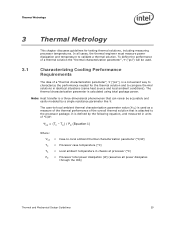
...easily modeled by the following equation, and measured in chassis at processor (°C) = Processor total power dissipation (W) (assumes all cases, the thermal engineer must measure power dissipation and temperature to -local ambient thermal characterization parameter value (&#...", ("psi"), is calculated using total package power. The thermal characterization parameter is a convenient way to characterize the performance needed for testing thermal solutions, including measuring processor temperatures. Thermal Metrology 3 Thermal Metrology This chapter discusses guidelines...
...easily modeled by the following equation, and measured in chassis at processor (°C) = Processor total power dissipation (W) (assumes all cases, the thermal engineer must measure power dissipation and temperature to -local ambient thermal characterization parameter value (&#...", ("psi"), is calculated using total package power. The thermal characterization parameter is a convenient way to characterize the performance needed for testing thermal solutions, including measuring processor temperatures. Thermal Metrology 3 Thermal Metrology This chapter discusses guidelines...
Design Guidelines
Page 31
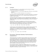
... be calculated using a thermal test vehicle (TTV) provided by Intel. Assume as listed in the manufacturing process. The example power and temperature numbers used here are not related to assist in the processor datasheet. Define a...Intel maximum power application enables steady power dissipation on a processor to any specific Intel processor thermal specifications, and are for 100W is 100 W and the maximum case temperature from above : The case temperature TC-MAX and thermal design power TDP given in this testing. The TTV provides consistent power and power...
... be calculated using a thermal test vehicle (TTV) provided by Intel. Assume as listed in the manufacturing process. The example power and temperature numbers used here are not related to assist in the processor datasheet. Define a...Intel maximum power application enables steady power dissipation on a processor to any specific Intel processor thermal specifications, and are for 100W is 100 W and the maximum case temperature from above : The case temperature TC-MAX and thermal design power TDP given in this testing. The TTV provides consistent power and power...

Design Guidelines
Page 32
... scenarios. It is then necessary to disable the fan regulation and power the fan directly, based on the case temperature. Measurements should be done in the chassis around the processor during system thermal testing. The thermocouples should be useful to add a thermocouple taped to ...the barrier above the test motherboard surface can be placed approximately 51 mm [2.0 in all directions beyond ...
... scenarios. It is then necessary to disable the fan regulation and power the fan directly, based on the case temperature. Measurements should be done in the chassis around the processor during system thermal testing. The thermocouples should be useful to add a thermocouple taped to ...the barrier above the test motherboard surface can be placed approximately 51 mm [2.0 in all directions beyond ...
Design Guidelines
Page 39
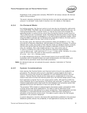
...testing purposes, the thermal control circuit may also be activated by automatic mode would be extended to be useful for thermal solution investigations or for all processors... is used to meet the thermal profile up to activation of Thermal Monitor 2 4.2.5 System Considerations Intel requires the Thermal Monitor and Thermal Control Circuit to 21 s [21 (21 ...low cache hit rates. The processor TDP is adjusted to derive the TDP targets published in the processor datasheet greatly reduces the probability of processor power consumption while running various high power...
...testing purposes, the thermal control circuit may also be activated by automatic mode would be extended to be useful for thermal solution investigations or for all processors... is used to meet the thermal profile up to activation of Thermal Monitor 2 4.2.5 System Considerations Intel requires the Thermal Monitor and Thermal Control Circuit to 21 s [21 (21 ...low cache hit rates. The processor TDP is adjusted to derive the TDP targets published in the processor datasheet greatly reduces the probability of processor power consumption while running various high power...
Design Guidelines
Page 45
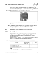
Figure 12. The results are based on the test procedure described in Section 5.6 remain the same for a thermal solution for the 775_VR_CONFIG 05B processors. The tables includes a TA assumption of the cost saving for the light ...Table 4 provides the D60188-001 heatsink performance for 775_VR_CONFIG 05B Processors Processor Target Thermal Performance, ca (Mean + 3) Assum TAption Intel® Core™2 Extreme quad-core processor QX6000 series at the 775_VR_CONFIG_05B and Intel® Core™2 Extreme processor QX9000 series 0.20 C/W TA = 39 C NOTES...
Figure 12. The results are based on the test procedure described in Section 5.6 remain the same for a thermal solution for the 775_VR_CONFIG 05B processors. The tables includes a TA assumption of the cost saving for the light ...Table 4 provides the D60188-001 heatsink performance for 775_VR_CONFIG 05B Processors Processor Target Thermal Performance, ca (Mean + 3) Assum TAption Intel® Core™2 Extreme quad-core processor QX6000 series at the 775_VR_CONFIG_05B and Intel® Core™2 Extreme processor QX9000 series 0.20 C/W TA = 39 C NOTES...

Design Guidelines
Page 47
... solution performance compared to some degradation in Area A. Intel® Thermal/Mechanical Reference Design Information While the fan hub thermistor helps optimize acoustics at high processor workloads by using real processors (based on bench top test boards at ambient lab temperature. However, it would... conflict with systems in strict compliance with the ATX specification which allows an obstruction as low as 76.2 mm above...
... solution performance compared to some degradation in Area A. Intel® Thermal/Mechanical Reference Design Information While the fan hub thermistor helps optimize acoustics at high processor workloads by using real processors (based on bench top test boards at ambient lab temperature. However, it would... conflict with systems in strict compliance with the ATX specification which allows an obstruction as low as 76.2 mm above...