Product Guide
Page 6
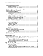
Intel Desktop Board DX58SO Product Guide Installing and Removing a Processor 31 Installing a Processor 31 Installing the Processor Fan Heat Sink 35 Connecting the Processor Fan Heat Sink Cable 35 Removing the Processor 36 Installing the ICH Heat Sink Decorative Cover (Optional 36 Installing the IOH Cooling Fan (Optional 37 Installing and Removing Memory 38 Guidelines for Memory Configuration 38...
Intel Desktop Board DX58SO Product Guide Installing and Removing a Processor 31 Installing a Processor 31 Installing the Processor Fan Heat Sink 35 Connecting the Processor Fan Heat Sink Cable 35 Removing the Processor 36 Installing the ICH Heat Sink Decorative Cover (Optional 36 Installing the IOH Cooling Fan (Optional 37 Installing and Removing Memory 38 Guidelines for Memory Configuration 38...
Product Guide
Page 7
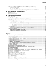
... Connecting the Processor Fan Heat Sink Cable to the Processor Fan Header ..........35 16. Single Channel Memory Configuration 39 21. Onboard Power Button 24 6. Location of the Standby Power Indicator 22 5. Intel Desktop Board DX58SO Mounting Screw Hole Locations 30 9. Installing the IOH Fan 37 18. Intel Desktop Board DX58SO ...Union Declaration of Conformity Statement 74 Product Ecology Statements 75 Recycling Considerations 75 Lead-free 2LI/Pb-free 2LI Board 78 Restriction of Hazardous Substances (RoHS 79 EU RoHS 79 China RoHS 80 EMC Regulations 82 Ensure Electromagnetic ...
... Connecting the Processor Fan Heat Sink Cable to the Processor Fan Header ..........35 16. Single Channel Memory Configuration 39 21. Onboard Power Button 24 6. Location of the Standby Power Indicator 22 5. Intel Desktop Board DX58SO Mounting Screw Hole Locations 30 9. Installing the IOH Fan 37 18. Intel Desktop Board DX58SO ...Union Declaration of Conformity Statement 74 Product Ecology Statements 75 Recycling Considerations 75 Lead-free 2LI/Pb-free 2LI Board 78 Restriction of Hazardous Substances (RoHS 79 EU RoHS 79 China RoHS 80 EMC Regulations 82 Ensure Electromagnetic ...
Product Guide
Page 8
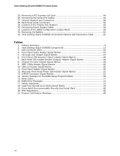
Location of the BIOS Configuration Jumper Block 55 32. Connecting Power Supply Cables 54 31. Location of the Chassis Fan Headers 53 30. Removing the Battery 61 33. LAN Connector LEDs 16 4. HD Audio Link Header Signal Names 47 6. Beep Codes 71... Jumper Settings for the BIOS Setup Program Modes 56 15. BIOS Error Messages 71 17. Connecting the Serial ATA Cables 45 27. IEEE 1394a Header Signal Names 49 10. Product Certification Markings 84 viii Intel Desktop Board DX58SO China RoHS Material Self Declaration Table 81 Tables 1. S/PDIF Connector Signal Names 51 14....
Location of the BIOS Configuration Jumper Block 55 32. Connecting Power Supply Cables 54 31. Location of the Chassis Fan Headers 53 30. Removing the Battery 61 33. LAN Connector LEDs 16 4. HD Audio Link Header Signal Names 47 6. Beep Codes 71... Jumper Settings for the BIOS Setup Program Modes 56 15. BIOS Error Messages 71 17. Connecting the Serial ATA Cables 45 27. IEEE 1394a Header Signal Names 49 10. Product Certification Markings 84 viii Intel Desktop Board DX58SO China RoHS Material Self Declaration Table 81 Tables 1. S/PDIF Connector Signal Names 51 14....
Product Guide
Page 20
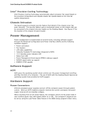
... turn off ). Intel Desktop Board DX58SO Product Guide Intel® Precision Cooling Technology Intel Precision Cooling Technology automatically adjust processor fan speed based on the processor temperature and adjusts chassis fan speeds based on the chassis that detects if the chassis cover has been removed. See Figure 27 for the location of ACPI with the Desktop Board requires an operating...
... turn off ). Intel Desktop Board DX58SO Product Guide Intel® Precision Cooling Technology Intel Precision Cooling Technology automatically adjust processor fan speed based on the processor temperature and adjusts chassis fan speeds based on the chassis that detects if the chassis cover has been removed. See Figure 27 for the location of ACPI with the Desktop Board requires an operating...

Product Guide
Page 21
... its last known awake state. 21 Desktop Board Features The Desktop Board has three power connectors. Fan Headers The function/operation of the fans is as needed. • All fan headers have a +12 V DC connection. The Desktop Board has a 4-pin processor fan header, one 4-pin and two 3-pin chassis fan headers, and one 3-pin IOH fan header. Instantly Available PC Technology CAUTIONS For...
... its last known awake state. 21 Desktop Board Features The Desktop Board has three power connectors. Fan Headers The function/operation of the fans is as needed. • All fan headers have a +12 V DC connection. The Desktop Board has a 4-pin processor fan header, one 4-pin and two 3-pin chassis fan headers, and one 3-pin IOH fan header. Instantly Available PC Technology CAUTIONS For...
Product Guide
Page 27
...using and modifying electronic equipment. Some circuitry on the board can continue to operate even though the front panel power button is not available, you can damage components. If such a station is off. 2 Installing and Replacing Desktop Board Components This chapter tells you how to: •... the Desktop Board • Install and remove a processor • Install the ICH heat sink decorative cover • Install the IOH heat sink fan • Install and remove memory • Install and remove a PCI Express x16 card • Connect the IDE and Serial ATA cables • Connect to...
...using and modifying electronic equipment. Some circuitry on the board can continue to operate even though the front panel power button is not available, you can damage components. If such a station is off. 2 Installing and Replacing Desktop Board Components This chapter tells you how to: •... the Desktop Board • Install and remove a processor • Install the ICH heat sink decorative cover • Install the IOH heat sink fan • Install and remove memory • Install and remove a PCI Express x16 card • Connect the IDE and Serial ATA cables • Connect to...

Product Guide
Page 35
... how to attach the processor fan heat sink to the Desktop Board, refer to the 4-pin processor fan header (see Figure 15). Figure 15. Connecting the Processor Fan Heat Sink Cable to the Processor Fan Header 35 Installing and Replacing Desktop Board Components Installing the Processor Fan Heat Sink Intel Desktop Board DX58SO has mounting holes for a processor fan heat sink. A fan with a 4-pin connector as...
... how to attach the processor fan heat sink to the Desktop Board, refer to the 4-pin processor fan header (see Figure 15). Figure 15. Connecting the Processor Fan Heat Sink Cable to the Processor Fan Header 35 Installing and Replacing Desktop Board Components Installing the Processor Fan Heat Sink Intel Desktop Board DX58SO has mounting holes for a processor fan heat sink. A fan with a 4-pin connector as...

Product Guide
Page 37
...the fan. Installing the IOH Fan 37 Attach the fan to the IOH fan header (Figure 17, D). Make sure that provided by the IOH passive heat sink, you can connect to the board's 3-pin IOH fan header to the heat sink by the arrow on page 27. 2. Installing and Replacing Desktop Board Components... Installing the IOH Cooling Fan (Optional) If your system application requires more cooling than that the fan airflow is down until the...
...the fan. Installing the IOH Fan 37 Attach the fan to the IOH fan header (Figure 17, D). Make sure that provided by the IOH passive heat sink, you can connect to the board's 3-pin IOH fan header to the heat sink by the arrow on page 27. 2. Installing and Replacing Desktop Board Components... Installing the IOH Cooling Fan (Optional) If your system application requires more cooling than that the fan airflow is down until the...
Product Guide
Page 53
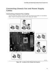
Installing and Replacing Desktop Board Components Connecting Chassis Fan and Power Supply Cables Connecting Chassis Fan Cables Connect chassis fan cables to the 3-pin and 4-pin chassis fan headers on the Desktop Board. Figure 29. Figure 29 shows the location of the Chassis Fan Headers 53 Location of the chassis fan headers.
Installing and Replacing Desktop Board Components Connecting Chassis Fan and Power Supply Cables Connecting Chassis Fan Cables Connect chassis fan cables to the 3-pin and 4-pin chassis fan headers on the Desktop Board. Figure 29. Figure 29 shows the location of the Chassis Fan Headers 53 Location of the chassis fan headers.


