
Product Guide
Page 5
...Passwords 18 Hardware Management 19 Hardware Monitoring and Fan Speed Control 19 Intel® Precision Cooling Technology 19 Chassis Intrusion 19 Power Management 20 Software Support 20 ACPI 20 Hardware Support 20 Power Connectors 20 Fan Headers 21 LAN Wake Capabilities 21 Instantly Available PC ...23 ENERGY STAR* Capable 23 Onboard Power Button 24 Onboard VR and CPU LEDs 25 Speaker...25 Battery ...26 Real-Time Clock 26 2 Installing and Replacing Desktop Board Components Before You Begin 27 Installation Precautions 28 Prevent Power Supply Overload 28 Observe Safety and ...
...Passwords 18 Hardware Management 19 Hardware Monitoring and Fan Speed Control 19 Intel® Precision Cooling Technology 19 Chassis Intrusion 19 Power Management 20 Software Support 20 ACPI 20 Hardware Support 20 Power Connectors 20 Fan Headers 21 LAN Wake Capabilities 21 Instantly Available PC ...23 ENERGY STAR* Capable 23 Onboard Power Button 24 Onboard VR and CPU LEDs 25 Speaker...25 Battery ...26 Real-Time Clock 26 2 Installing and Replacing Desktop Board Components Before You Begin 27 Installation Precautions 28 Prevent Power Supply Overload 28 Observe Safety and ...
Product Guide
Page 6
Intel Desktop Board DX48BT2 Product Guide Installing and Removing a Processor 31 Installing a Processor 31 Installing the Processor Fan Heat Sink 35 Connecting the Processor Fan Heat Sink Cable 35 ... Header 49 Consumer IR (CIR) Headers 49 Chassis Intrusion Header 50 IEEE 1394a Header 51 USB 2.0 Headers 51 Front Panel Header 52 Alternate Front Panel Power LED Header 52 S/PDIF Connector 52 Connecting to the Flexible Audio System 53 Connecting Chassis Fan and...
Intel Desktop Board DX48BT2 Product Guide Installing and Removing a Processor 31 Installing a Processor 31 Installing the Processor Fan Heat Sink 35 Connecting the Processor Fan Heat Sink Cable 35 ... Header 49 Consumer IR (CIR) Headers 49 Chassis Intrusion Header 50 IEEE 1394a Header 51 USB 2.0 Headers 51 Front Panel Header 52 Alternate Front Panel Power LED Header 52 S/PDIF Connector 52 Connecting to the Flexible Audio System 53 Connecting Chassis Fan and...

Product Guide
Page 7
...Power Indicator 22 4. Installing the I/O Shield 29 7. Lift the Load Plate 32 10. Remove the Protective Socket Cover 32 11. Remove the Processor from the Protective Processor Cover 33 12. Dual Channel Memory Configuration with Two DIMMs 38 18. Installing PCI Express x16 Graphics Cards 43 23. Desktop Board DX48BT2...Component Certifications 85 Figures 1. Close the Load Plate 34 14. Installing a PCI Express x16 Card 44 24. Desktop Board DX48BT2 Components 11 2. Installing a DIMM 41 22. Contents Configuring for External RAID Using Marvell* Storage Technology 69 Configuring...
...Power Indicator 22 4. Installing the I/O Shield 29 7. Lift the Load Plate 32 10. Remove the Protective Socket Cover 32 11. Remove the Processor from the Protective Processor Cover 33 12. Dual Channel Memory Configuration with Two DIMMs 38 18. Installing PCI Express x16 Graphics Cards 43 23. Desktop Board DX48BT2...Component Certifications 85 Figures 1. Close the Load Plate 34 14. Installing a PCI Express x16 Card 44 24. Desktop Board DX48BT2 Components 11 2. Installing a DIMM 41 22. Contents Configuring for External RAID Using Marvell* Storage Technology 69 Configuring...
Product Guide
Page 8
Intel Desktop Board DX48BT2 Product Guide 25. Connecting the IDE Cable 46 26. Internal Headers and Connectors 48 28. Feature Summary 9 2. IEEE 1394a Header Signal Names 51 10. USB 2.0 ... 5. Back Panel CIR Header Emitter (Output) Header Signal Names 50 8. Safety Standards 73 18. Product Certification Markings 84 viii Desktop Board DX48BT2 Components 12 3. HD Audio Link Header Signal Names 49 6. Alternate Front Panel Power LED Header Signal Names 52 13. BIOS Error Messages 71 17. LAN Connector LEDs 16 4. Jumper Settings for the...
Intel Desktop Board DX48BT2 Product Guide 25. Connecting the IDE Cable 46 26. Internal Headers and Connectors 48 28. Feature Summary 9 2. IEEE 1394a Header Signal Names 51 10. USB 2.0 ... 5. Back Panel CIR Header Emitter (Output) Header Signal Names 50 8. Safety Standards 73 18. Product Certification Markings 84 viii Desktop Board DX48BT2 Components 12 3. HD Audio Link Header Signal Names 49 6. Alternate Front Panel Power LED Header Signal Names 52 13. BIOS Error Messages 71 17. LAN Connector LEDs 16 4. Jumper Settings for the...

Product Guide
Page 10
...16 Mb symmetrical flash memory device • Support for SMBIOS • Intel® Rapid BIOS Boot • Intel® Express BIOS Update Power Management • Support for Advanced Configuration and Power Interface (ACPI) • Suspend to RAM (STR) • Wake... values Related Links: For more information about Desktop Board DX48BT2, including the Technical Product Specification (TPS), BIOS updates, and device drivers, go to: http://support.intel.com/support/motherboards/desktop/ Supported Operating Systems The Desktop Board supports the following operating systems: • ...
...16 Mb symmetrical flash memory device • Support for SMBIOS • Intel® Rapid BIOS Boot • Intel® Express BIOS Update Power Management • Support for Advanced Configuration and Power Interface (ACPI) • Suspend to RAM (STR) • Wake... values Related Links: For more information about Desktop Board DX48BT2, including the Technical Product Specification (TPS), BIOS updates, and device drivers, go to: http://support.intel.com/support/motherboards/desktop/ Supported Operating Systems The Desktop Board supports the following operating systems: • ...
Product Guide
Page 12
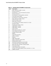
Desktop Board DX48BT2 Components Label A B C D E F G H I J K L M N O P Q R S T U V W X Y Z AA BB CC DD EE FF GG Description Rear chassis fan header 2 (4-pin) PCI bus connector 2 PCI Express 1.1 x16 (x4 ...headers Speaker IEEE 1394a header BIOS configuration jumper block Onboard power button Alternate front panel power LED header Front panel CIR receiver (input) header Back panel CIR transmitter (output) header Front panel header High Definition Audio Link header Auxiliary PCI Express graphics power connector (1 x 4 pin) S/PDIF connector 12 Intel Desktop Board DX48BT2 Product Guide Table 2.
Desktop Board DX48BT2 Components Label A B C D E F G H I J K L M N O P Q R S T U V W X Y Z AA BB CC DD EE FF GG Description Rear chassis fan header 2 (4-pin) PCI bus connector 2 PCI Express 1.1 x16 (x4 ...headers Speaker IEEE 1394a header BIOS configuration jumper block Onboard power button Alternate front panel power LED header Front panel CIR receiver (input) header Back panel CIR transmitter (output) header Front panel header High Definition Audio Link header Auxiliary PCI Express graphics power connector (1 x 4 pin) S/PDIF connector 12 Intel Desktop Board DX48BT2 Product Guide Table 2.
Product Guide
Page 13
... on installing or upgrading the processor, page 31 in Chapter 2 • Supported processors for more information about: • Desktop Board DX48BT2 http://www.intel.com/design/motherbd http://support.intel.com/support/motherboards/ desktop • Supported processors http://www.intel.com/go /findCPU 13 Desktop Board DX48BT2 supports an Intel processor in damage to the board, or the system may not function properly.
... on installing or upgrading the processor, page 31 in Chapter 2 • Supported processors for more information about: • Desktop Board DX48BT2 http://www.intel.com/design/motherbd http://support.intel.com/support/motherboards/ desktop • Supported processors http://www.intel.com/go /findCPU 13 Desktop Board DX48BT2 supports an Intel processor in damage to the board, or the system may not function properly.
Product Guide
Page 14
The Desktop Board supports the dual or single channel memory configurations defined below: • Four 240...you will attempt to this effect on the screen at power up. Intel Desktop Board DX48BT2 Product Guide Main Memory NOTE To be fully compliant with all applicable Intel ® SDRAM memory specifications, the board should be populated with gold-plated contacts. •... the memory controller for more information about: • SDRAM specifications, http://www.intel.com/technology/memory/ • Installing memory, page 37 in DIMM 0 and DIMM 1 of 4 GB utilizing 1 Gb memory technology...
The Desktop Board supports the dual or single channel memory configurations defined below: • Four 240...you will attempt to this effect on the screen at power up. Intel Desktop Board DX48BT2 Product Guide Main Memory NOTE To be fully compliant with all applicable Intel ® SDRAM memory specifications, the board should be populated with gold-plated contacts. •... the memory controller for more information about: • SDRAM specifications, http://www.intel.com/technology/memory/ • Installing memory, page 37 in DIMM 0 and DIMM 1 of 4 GB utilizing 1 Gb memory technology...

Product Guide
Page 16
Intel Desktop Board DX48BT2 Product Guide LAN Subsystem The LAN subsystem includes: • Intel ICH9R • Intel 82566DC Gigabit (10/100/1000 Mb/s) Ethernet LAN controller • RJ-45 LAN connector with integrated status LEDs The subsystem features: • CSMA/CD protocol engine • LAN connect interface between ICH9R and the LAN controller • PCI bus power... management Related Links: Go to the following link for information about LAN software and drivers: http://support.intel.com/support/motherboards/desktop Two LEDs are built into the RJ...
Intel Desktop Board DX48BT2 Product Guide LAN Subsystem The LAN subsystem includes: • Intel ICH9R • Intel 82566DC Gigabit (10/100/1000 Mb/s) Ethernet LAN controller • RJ-45 LAN connector with integrated status LEDs The subsystem features: • CSMA/CD protocol engine • LAN connect interface between ICH9R and the LAN controller • PCI bus power... management Related Links: Go to the following link for information about LAN software and drivers: http://support.intel.com/support/motherboards/desktop Two LEDs are built into the RJ...

Product Guide
Page 17
... • Up to two onboard headers) via a discrete controller. distributed parity For information on configuring your system for RAID using Intel® Matrix Storage Technology see Chapter 4. USB 2.0 ports are backward compatible with USB 1.1 devices. USB 2.0 support requires both...transfer rates. data striping and data mirroring • RAID 5 - Legacy I/O Desktop Board DX48BT2 includes an I /O features: • Consumer Infrared (CIR) support • Low pin count (LPC) interface • Intelligent power management, including a programmable wake up to 12 USB 2.0 ports (eight ports ...
... • Up to two onboard headers) via a discrete controller. distributed parity For information on configuring your system for RAID using Intel® Matrix Storage Technology see Chapter 4. USB 2.0 ports are backward compatible with USB 1.1 devices. USB 2.0 support requires both...transfer rates. data striping and data mirroring • RAID 5 - Legacy I/O Desktop Board DX48BT2 includes an I /O features: • Consumer Infrared (CIR) support • Low pin count (LPC) interface • Intelligent power management, including a programmable wake up to 12 USB 2.0 ports (eight ports ...
Product Guide
Page 18
Intel Desktop Board DX48BT2 Product Guide Expandability Desktop Board DX48BT2 provides the following restrictions: • The supervisor password gives unrestricted access to view and change all Setup options. You do not need to run the ... If you must enter either the supervisor password or the user password to a x16 connector) • Two PCI bus connectors BIOS The BIOS provides the Power-On Self-Test (POST), the BIOS Setup program, and the PCI/PCI Express and IDE auto-configuration utilities. The BIOS can be accessed and who...
Intel Desktop Board DX48BT2 Product Guide Expandability Desktop Board DX48BT2 provides the following restrictions: • The supervisor password gives unrestricted access to view and change all Setup options. You do not need to run the ... If you must enter either the supervisor password or the user password to a x16 connector) • Two PCI bus connectors BIOS The BIOS provides the Power-On Self-Test (POST), the BIOS Setup program, and the PCI/PCI Express and IDE auto-configuration utilities. The BIOS can be accessed and who...
Product Guide
Page 19
... Management The hardware management features of Desktop Board DX48BT2 enable the board to be connected to boot the computer. Chassis Intrusion The board supports a chassis security feature that ...power supply voltages to Clearing Passwords on page 57. See Figure 27 for all onboard fans, that can enter either password to the chassis intrusion header on the Desktop Board. Desktop Board... above and below acceptable values • Intel® Precision Cooling Technology fan speed control, delivering acoustically- The board has several hardware management features including the following...
... Management The hardware management features of Desktop Board DX48BT2 enable the board to be connected to boot the computer. Chassis Intrusion The board supports a chassis security feature that ...power supply voltages to Clearing Passwords on page 57. See Figure 27 for all onboard fans, that can enter either password to the chassis intrusion header on the Desktop Board. Desktop Board... above and below acceptable values • Intel® Precision Cooling Technology fan speed control, delivering acoustically- The board has several hardware management features including the following...
Product Guide
Page 20
... program's Boot menu. Hardware Support Power Connectors ATX12V-compliant power supplies can be set by using the Last Power State feature in before power was interrupted (either on page 55 for the location of ACPI with the Desktop Board requires an operating system that provides full ACPI support. Intel Desktop Board DX48BT2 Product Guide Power Management Power management is implemented at several...
... program's Boot menu. Hardware Support Power Connectors ATX12V-compliant power supplies can be set by using the Last Power State feature in before power was interrupted (either on page 55 for the location of ACPI with the Desktop Board requires an operating system that provides full ACPI support. Intel Desktop Board DX48BT2 Product Guide Power Management Power management is implemented at several...

Product Guide
Page 21
... upon detecting a Magic Packet* frame, it asserts a wake-up signal that can damage the power supply. While in memory. Failure to provide adequate standby current when using this Desktop Board must be capable of delivering adequate +5 V standby current. If the standby current necessary to support... multiple wake events from the PCI and/or USB buses exceeds power supply capacity, the Desktop Board may lose register settings stored in the S3 sleep state, the computer will appear to a tachometer input of the hardware...
... upon detecting a Magic Packet* frame, it asserts a wake-up signal that can damage the power supply. While in memory. Failure to provide adequate standby current when using this Desktop Board must be capable of delivering adequate +5 V standby current. If the standby current necessary to support... multiple wake events from the PCI and/or USB buses exceeds power supply capacity, the Desktop Board may lose register settings stored in the S3 sleep state, the computer will appear to a tachometer input of the hardware...

Product Guide
Page 22
... memory module sockets and the PCI bus connectors. Location of the Standby Power Indicator 22 Intel Desktop Board DX48BT2 Product Guide The Desktop Board supports the PCI Bus Power Management Interface Specification. Figure 3. Add-in Figure 3, is lit when there is standby power still present on the board even when the computer appears to be used to wake the computer...
... memory module sockets and the PCI bus connectors. Location of the Standby Power Indicator 22 Intel Desktop Board DX48BT2 Product Guide The Desktop Board supports the PCI Bus Power Management Interface Specification. Figure 3. Add-in Figure 3, is lit when there is standby power still present on the board even when the computer appears to be used to wake the computer...

Product Guide
Page 24
Perform the procedure described in this section only at integration facilities to remove standby power before making changes to the system configuration, or for three seconds. If such a station is recommended for all other instances ...ESD workstation using the onboard power button, keep the button pressed down for testing purposes. A power button on the Desktop Board (see Figure 4) can be used to turn off . The power button on the front panel is not available, you can damage components. Intel Desktop Board DX48BT2 Product Guide Onboard Power Button CAUTION Electrostatic discharge (...
Perform the procedure described in this section only at integration facilities to remove standby power before making changes to the system configuration, or for three seconds. If such a station is recommended for all other instances ...ESD workstation using the onboard power button, keep the button pressed down for testing purposes. A power button on the Desktop Board (see Figure 4) can be used to turn off . The power button on the front panel is not available, you can damage components. Intel Desktop Board DX48BT2 Product Guide Onboard Power Button CAUTION Electrostatic discharge (...

Product Guide
Page 25
... processor that could affect performance. The speaker provides audible error code (beep code) information during the Power-On Self-Test (POST). Location of the board's beep codes. 25 Refer to the standby power indicator (see Figure 3), the Desktop Board contains two other LEDs (see Figure 5): • The VR LED (Figure 5, A) indicates an elevated temperature in...
... processor that could affect performance. The speaker provides audible error code (beep code) information during the Power-On Self-Test (POST). Location of the board's beep codes. 25 Refer to the standby power indicator (see Figure 3), the Desktop Board contains two other LEDs (see Figure 5): • The VR LED (Figure 5, A) indicates an elevated temperature in...

Product Guide
Page 27
...pad. Disconnect the computer from its power source and from any telecommunications links, networks, or modems before you begin: • Always follow the steps in each procedure in personal injury or equipment damage. 2 Installing and Replacing Desktop Board Components This chapter tells you how... to: • Install the I/O shield • Install and remove the Desktop Board • Install and remove a processor • Install the ICH heat sink ...
...pad. Disconnect the computer from its power source and from any telecommunications links, networks, or modems before you begin: • Always follow the steps in each procedure in personal injury or equipment damage. 2 Installing and Replacing Desktop Board Components This chapter tells you how... to: • Install the I/O shield • Install and remove the Desktop Board • Install and remove a processor • Install the ICH heat sink ...

Product Guide
Page 28
Intel Desktop Board DX48BT2 Product Guide Installation Precautions When you to refer computer servicing to qualified technical personnel. If the instructions for associated modules, contact the supplier to Appendix B ... follow the instructions in the installation instructions. To avoid overloading the power supply, make sure that instruct you install and test the Intel Desktop Board, observe all the modules within the computer is less than the output current rating of each of the power supplies output circuits. Observe Safety and Regulatory Requirements Read and follow...
Intel Desktop Board DX48BT2 Product Guide Installation Precautions When you to refer computer servicing to qualified technical personnel. If the instructions for associated modules, contact the supplier to Appendix B ... follow the instructions in the installation instructions. To avoid overloading the power supply, make sure that instruct you install and test the Intel Desktop Board, observe all the modules within the computer is less than the output current rating of each of the power supplies output circuits. Observe Safety and Regulatory Requirements Read and follow...

Product Guide
Page 30
... removing the Desktop Board. Failure to your chassis manual for Desktop Board DX48BT2. Refer to disconnect the power before performing the procedures described here. Figure 7. Desktop Board DX48BT2 Mounting Screw Hole Locations 30 Disconnect the computer from its power source before you open the computer can result in personal injury or equipment damage. Intel Desktop Board DX48BT2 Product Guide Installing and Removing the Desktop Board CAUTION...
... removing the Desktop Board. Failure to your chassis manual for Desktop Board DX48BT2. Refer to disconnect the power before performing the procedures described here. Figure 7. Desktop Board DX48BT2 Mounting Screw Hole Locations 30 Disconnect the computer from its power source before you open the computer can result in personal injury or equipment damage. Intel Desktop Board DX48BT2 Product Guide Installing and Removing the Desktop Board CAUTION...

