Product Guide
Page 3
...without further evaluation by Intel. The suitability of this manual: CAUTION Cautions warn the user about how to prevent damage to hardware or loss of product features 2 Installing and Replacing Desktop Board Components: instructions on how to install the Desktop Board and other hardware components... in this Product Guide are arranged as follows: 1 Desktop Board Features: a summary of data. It is intended for other PC or embedded non-PC applications or other environments, such as medical, industrial, alarm systems, test equipment, etc. Use Only for Intel® Desktop Board DX48BT2.
...without further evaluation by Intel. The suitability of this manual: CAUTION Cautions warn the user about how to prevent damage to hardware or loss of product features 2 Installing and Replacing Desktop Board Components: instructions on how to install the Desktop Board and other hardware components... in this Product Guide are arranged as follows: 1 Desktop Board Features: a summary of data. It is intended for other PC or embedded non-PC applications or other environments, such as medical, industrial, alarm systems, test equipment, etc. Use Only for Intel® Desktop Board DX48BT2.

Product Guide
Page 5
...18 PCI and PCI Express* Auto Configuration 18 Security Passwords 18 Hardware Management 19 Hardware Monitoring and Fan Speed Control 19 Intel® Precision Cooling Technology 19 Chassis Intrusion 19 Power Management 20 Software Support 20 ACPI 20 Hardware Support 20 Power Connectors...23 Onboard Power Button 24 Onboard VR and CPU LEDs 25 Speaker...25 Battery ...26 Real-Time Clock 26 2 Installing and Replacing Desktop Board Components Before You Begin 27 Installation Precautions 28 Prevent Power Supply Overload 28 Observe Safety and Regulatory Requirements 28 Installing the I/O ...
...18 PCI and PCI Express* Auto Configuration 18 Security Passwords 18 Hardware Management 19 Hardware Monitoring and Fan Speed Control 19 Intel® Precision Cooling Technology 19 Chassis Intrusion 19 Power Management 20 Software Support 20 ACPI 20 Hardware Support 20 Power Connectors...23 Onboard Power Button 24 Onboard VR and CPU LEDs 25 Speaker...25 Battery ...26 Real-Time Clock 26 2 Installing and Replacing Desktop Board Components Before You Begin 27 Installation Precautions 28 Prevent Power Supply Overload 28 Observe Safety and Regulatory Requirements 28 Installing the I/O ...
Product Guide
Page 6
Intel Desktop Board DX48BT2 Product Guide Installing and Removing a Processor 31 Installing a Processor 31 Installing the Processor Fan Heat Sink 35 Connecting the Processor Fan Heat Sink Cable 35 ... 54 Connecting Chassis Fan Cables 54 Connecting Power Supply Cables 55 Setting the BIOS Configuration Jumper 56 Clearing Passwords 57 Replacing the Battery 58 3 Updating the BIOS Updating the BIOS with the Intel® Express BIOS Update Utility 63 Updating the BIOS with the ISO Image BIOS Update File or the Iflash...
Intel Desktop Board DX48BT2 Product Guide Installing and Removing a Processor 31 Installing a Processor 31 Installing the Processor Fan Heat Sink 35 Connecting the Processor Fan Heat Sink Cable 35 ... 54 Connecting Chassis Fan Cables 54 Connecting Power Supply Cables 55 Setting the BIOS Configuration Jumper 56 Clearing Passwords 57 Replacing the Battery 58 3 Updating the BIOS Updating the BIOS with the Intel® Express BIOS Update Utility 63 Updating the BIOS with the ISO Image BIOS Update File or the Iflash...

Product Guide
Page 26
The battery on the Desktop Board keeps the clock current when the computer is turned off . 26 Intel Desktop Board DX48BT2 Product Guide Battery A battery on the Desktop Board keeps the values in CMOS RAM and the clock current when the computer is turned off . Go to page 58 for instructions on how to replace the battery. Real-Time Clock The Desktop Board has a time-of-day clock and 100-year calendar.
The battery on the Desktop Board keeps the clock current when the computer is turned off . 26 Intel Desktop Board DX48BT2 Product Guide Battery A battery on the Desktop Board keeps the values in CMOS RAM and the clock current when the computer is turned off . Go to page 58 for instructions on how to replace the battery. Real-Time Clock The Desktop Board has a time-of-day clock and 100-year calendar.

Product Guide
Page 27
... safety practices and regulatory compliance required for using an antistatic wrist strap and a conductive foam pad. Some circuitry on the board can continue to operate even though the front panel power button is not available, you can provide some ESD protection by... this chapter only at an ESD workstation using and modifying electronic equipment. 2 Installing and Replacing Desktop Board Components This chapter tells you how to: • Install the I/O shield • Install and remove the Desktop Board • Install and remove a processor • Install the ICH heat sink decorative cover...
... safety practices and regulatory compliance required for using an antistatic wrist strap and a conductive foam pad. Some circuitry on the board can continue to operate even though the front panel power button is not available, you can provide some ESD protection by... this chapter only at an ESD workstation using and modifying electronic equipment. 2 Installing and Replacing Desktop Board Components This chapter tells you how to: • Install the I/O shield • Install and remove the Desktop Board • Install and remove a processor • Install the ICH heat sink decorative cover...

Product Guide
Page 29
... internal components from the chassis supplier. Press the shield into place so that it fits tightly and securely. Figure 6. Install the I /O Shield 29 Installing and Replacing Desktop Board Components Installing the I/O Shield The Desktop Board comes with an I/O shield.
... internal components from the chassis supplier. Press the shield into place so that it fits tightly and securely. Figure 6. Install the I /O Shield 29 Installing and Replacing Desktop Board Components Installing the I/O Shield The Desktop Board comes with an I/O shield.

Product Guide
Page 31
... and away from the computer; Observe the precautions in "Before You Begin" on page 22). Installing and Replacing Desktop Board Components Installing and Removing a Processor Instructions on how to do so could damage the processor and the board. Open the socket lever by unplugging the power cord from the socket (Figure 8, A and B). the standby...
... and away from the computer; Observe the precautions in "Before You Begin" on page 22). Installing and Replacing Desktop Board Components Installing and Removing a Processor Instructions on how to do so could damage the processor and the board. Open the socket lever by unplugging the power cord from the socket (Figure 8, A and B). the standby...

Product Guide
Page 32
Lift the Load Plate 4. Always replace the socket cover if the processor is removed from the load plate (Figure 10). Remove the Protective Socket Cover 32 Figure 10. Lift the load plate (Figure 9, A). Intel Desktop Board DX48BT2 Product Guide 3. Do not touch the socket contacts (Figure 9, B). Do not discard the protective socket cover. Remove the plastic protective socket cover from the socket. Figure 9.
Lift the Load Plate 4. Always replace the socket cover if the processor is removed from the load plate (Figure 10). Remove the Protective Socket Cover 32 Figure 10. Lift the load plate (Figure 9, A). Intel Desktop Board DX48BT2 Product Guide 3. Do not touch the socket contacts (Figure 9, B). Do not discard the protective socket cover. Remove the plastic protective socket cover from the socket. Figure 9.

Product Guide
Page 33
...33 Figure 11. Align notches (Figure 12, B) with your fingers align to touch the bottom of the processor (see Figure 11). Always replace the processor cover if the processor is removed from the Protective Processor Cover 6. Hold the processor with the socket (Figure 12, C). Figure...Lower the processor straight down without tilting or sliding it in Figure 12. Do not discard the protective processor cover. Installing and Replacing Desktop Board Components 5. Remove the processor from the protective processor cover. Make sure your thumb and index fingers oriented as shown in the socket...
...33 Figure 11. Align notches (Figure 12, B) with your fingers align to touch the bottom of the processor (see Figure 11). Always replace the processor cover if the processor is removed from the Protective Processor Cover 6. Hold the processor with the socket (Figure 12, C). Figure...Lower the processor straight down without tilting or sliding it in Figure 12. Do not discard the protective processor cover. Installing and Replacing Desktop Board Components 5. Remove the processor from the protective processor cover. Make sure your thumb and index fingers oriented as shown in the socket...

Product Guide
Page 35
... operate at full speed. Connecting the Processor Fan Heat Sink Cable to the 4-pin processor fan header (see Figure 14). Installing and Replacing Desktop Board Components Installing the Processor Fan Heat Sink Desktop Board DX48BT2 has mounting holes for a processor fan heat sink. For instructions on how to attach the processor fan heat sink to the...
... operate at full speed. Connecting the Processor Fan Heat Sink Cable to the 4-pin processor fan header (see Figure 14). Installing and Replacing Desktop Board Components Installing the Processor Fan Heat Sink Desktop Board DX48BT2 has mounting holes for a processor fan heat sink. For instructions on how to attach the processor fan heat sink to the...
Product Guide
Page 37
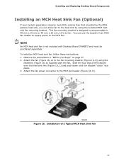
... to the heat sink by using the fasteners (Figure 16, A) supplied with Desktop Board DX48BT2 and must be purchased separately. This fan mounting bracket is not included with the fan. Installing and Replacing Desktop Board Components Installing an MCH Heat Sink Fan (Optional) If your system application requires more... MCH cooling than that provided by the MCH passive heat sink, you can use the board's 3-pin MCH fan header to supply...
... to the heat sink by using the fasteners (Figure 16, A) supplied with Desktop Board DX48BT2 and must be purchased separately. This fan mounting bracket is not included with the fan. Installing and Replacing Desktop Board Components Installing an MCH Heat Sink Fan (Optional) If your system application requires more... MCH cooling than that provided by the MCH passive heat sink, you can use the board's 3-pin MCH fan header to supply...

Product Guide
Page 39
Dual Channel Memory Configuration with Four DIMMs Three DIMMs If you want to use three DIMMs in a dual-channel configuration, install a matched pair of DIMMs equal in speed and size in DIMM 0 (blue) and DIMM 1 (black) of channel B (see Figure 19). Figure 19. Dual Channel Memory Configuration with Three DIMMs NOTE All other memory configurations will result in either DIMM 0 or DIMM 1 of channel A. Installing and Replacing Desktop Board Components Figure 18. Install a DIMM equal in speed and total size of the DIMMs installed in channel A in single channel memory operation. 39
Dual Channel Memory Configuration with Four DIMMs Three DIMMs If you want to use three DIMMs in a dual-channel configuration, install a matched pair of DIMMs equal in speed and size in DIMM 0 (blue) and DIMM 1 (black) of channel B (see Figure 19). Figure 19. Dual Channel Memory Configuration with Three DIMMs NOTE All other memory configurations will result in either DIMM 0 or DIMM 1 of channel A. Installing and Replacing Desktop Board Components Figure 18. Install a DIMM equal in speed and total size of the DIMMs installed in channel A in single channel memory operation. 39

Product Guide
Page 41
Position the DIMM above the socket. Replace the computer's cover and reconnect the AC power cord. 41 Remove the computer's cover and locate the DIMM sockets (see inset in "Before You Begin" ... anti-static package. 6. Make sure the clips at the bottom edge of the DIMM socket(s) are firmly in the socket (see Figure 21). Installing and Replacing Desktop Board Components To install a DIMM, follow these steps: 1.
Position the DIMM above the socket. Replace the computer's cover and reconnect the AC power cord. 41 Remove the computer's cover and locate the DIMM sockets (see inset in "Before You Begin" ... anti-static package. 6. Make sure the clips at the bottom edge of the DIMM socket(s) are firmly in the socket (see Figure 21). Installing and Replacing Desktop Board Components To install a DIMM, follow these steps: 1.

Product Guide
Page 42
... socket. Reinstall and reconnect any parts you removed or disconnected to the computer. Replace the computer's cover and reconnect the AC power cord. 42 Remove the AC power cord from the socket, and store it away from the computer. 4. Intel Desktop Board DX48BT2 Product Guide Removing DIMMs To remove a DIMM, follow these steps: 1. Turn off...
... socket. Reinstall and reconnect any parts you removed or disconnected to the computer. Replace the computer's cover and reconnect the AC power cord. 42 Remove the AC power cord from the socket, and store it away from the computer. 4. Intel Desktop Board DX48BT2 Product Guide Removing DIMMs To remove a DIMM, follow these steps: 1. Turn off...
Product Guide
Page 43
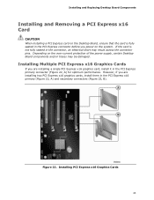
... 22, A) and secondary connectors (Figure 22, B). However, if you power on the over-current protection of the power supply, certain Desktop Board components and/or traces may result across the connector pins. Figure 22. Installing and Replacing Desktop Board Components Installing and Removing a PCI Express x16 Card CAUTION When installing a PCI Express card on the...
... 22, A) and secondary connectors (Figure 22, B). However, if you power on the over-current protection of the power supply, certain Desktop Board components and/or traces may result across the connector pins. Figure 22. Installing and Replacing Desktop Board Components Installing and Removing a PCI Express x16 Card CAUTION When installing a PCI Express card on the...

Product Guide
Page 45
Push the card ejector lever down using the tip of a pencil or similar tool (Figure 24, B) in "Before You Begin" on page 27. 2. This will release the card from a connector: 1. Pull the card straight up. Removing a PCI Express x16 Card 45 Remove the screw (Figure 24, A) that secures the card's metal bracket to remove a PCI Express x16 card from the connector (C). 4. Figure 24. Observe the precautions in the notch. Installing and Replacing Desktop Board Components Removing a PCI Express x16 Card Follow these instructions to the chassis back panel. 3.
Push the card ejector lever down using the tip of a pencil or similar tool (Figure 24, B) in "Before You Begin" on page 27. 2. This will release the card from a connector: 1. Pull the card straight up. Removing a PCI Express x16 Card 45 Remove the screw (Figure 24, A) that secures the card's metal bracket to remove a PCI Express x16 card from the connector (C). 4. Figure 24. Observe the precautions in the notch. Installing and Replacing Desktop Board Components Removing a PCI Express x16 Card Follow these instructions to the chassis back panel. 3.

Product Guide
Page 47
Attach one end of the cable to the SATA drive (Figure 26, B). Figure 26. Installing and Replacing Desktop Board Components Connecting the Serial ATA (SATA) Cables SATA cables support the Serial ATA protocol. Observe the precaution in "Before You Begin" on the board (Figure 26, A) and attach the other end of the SATA cable to one internal SATA drive to connect one of the SATA connectors on page 27. 2. Each cable can be used to the Desktop Board. Connecting a Serial ATA Cable 47 For correct cable function: 1.
Attach one end of the cable to the SATA drive (Figure 26, B). Figure 26. Installing and Replacing Desktop Board Components Connecting the Serial ATA (SATA) Cables SATA cables support the Serial ATA protocol. Observe the precaution in "Before You Begin" on the board (Figure 26, A) and attach the other end of the SATA cable to one internal SATA drive to connect one of the SATA connectors on page 27. 2. Each cable can be used to the Desktop Board. Connecting a Serial ATA Cable 47 For correct cable function: 1.

Product Guide
Page 49
... and a "learning" infrared input. Table 4 shows the pin assignments and signal names for the HD Audio Link header. Table 5. Installing and Replacing Desktop Board Components Front Panel Audio Header Figure 27, A shows the location of the front panel audio header. Table 4. HD Audio Link Header Signal Names ...Pin Signal Name 2 Ground 4 3.3 Vcc 6 Ground 8 3.3 Vcc 10 +12 V 12 Key 14 3.3 V STBY 16 Ground Consumer IR (CIR) Headers The Desktop Board has two CIR headers: the input or receiver header (Figure 27, D) and the output or emitter header (Figure 27, C).
... and a "learning" infrared input. Table 4 shows the pin assignments and signal names for the HD Audio Link header. Table 5. Installing and Replacing Desktop Board Components Front Panel Audio Header Figure 27, A shows the location of the front panel audio header. Table 4. HD Audio Link Header Signal Names ...Pin Signal Name 2 Ground 4 3.3 Vcc 6 Ground 8 3.3 Vcc 10 +12 V 12 Key 14 3.3 V STBY 16 Ground Consumer IR (CIR) Headers The Desktop Board has two CIR headers: the input or receiver header (Figure 27, D) and the output or emitter header (Figure 27, C).

Product Guide
Page 51
... no pin) Pin Signal Name 2 TPA1- 4 Ground 6 TPA2- 8 +12 V 10 Ground USB 2.0 Headers Figure 27, G shows the location of the IEEE 1394a header. Installing and Replacing Desktop Board Components IEEE 1394a Header Figure 27, F shows the location of the USB 2.0 headers. USB Port B Signal Name Power (+5 V) DD+ Ground No Connection NOTE Computer systems...
... no pin) Pin Signal Name 2 TPA1- 4 Ground 6 TPA2- 8 +12 V 10 Ground USB 2.0 Headers Figure 27, G shows the location of the IEEE 1394a header. Installing and Replacing Desktop Board Components IEEE 1394a Header Figure 27, F shows the location of the USB 2.0 headers. USB Port B Signal Name Power (+5 V) DD+ Ground No Connection NOTE Computer systems...

Product Guide
Page 53
... After installing the IDT* audio driver from the Intel® Express Installer DVD-ROM, the multi-channel audio feature can be enabled. The default connector assignments are connected to this output. 53 Figure 28 shows the back panel audio connectors. Installing and Replacing Desktop Board Components Connecting to power either headphones or amplified speakers...
... After installing the IDT* audio driver from the Intel® Express Installer DVD-ROM, the multi-channel audio feature can be enabled. The default connector assignments are connected to this output. 53 Figure 28 shows the back panel audio connectors. Installing and Replacing Desktop Board Components Connecting to power either headphones or amplified speakers...


