Product Guide
Page 5
...20 Hardware Management 21 Hardware Monitoring and Fan Speed Control 21 Intel® Precision Cooling Technology 21 Chassis Intrusion 21 Power Management 22 Software Support 22 ACPI 22 Hardware Support 22 Power Connectors 22 Fan Headers 23 LAN Wake Capabilities 23 Instantly Available ... Compliance 25 Onboard Power Button 26 Processor and Voltage Regulator LEDs 27 Back to BIOS Button 28 Speaker...29 Battery ...29 Real-Time Clock 29 2 Installing and Replacing Desktop Board Components Before You Begin 31 Installation Precautions 32 Prevent Power Supply Overload 32 Observe Safety...
...20 Hardware Management 21 Hardware Monitoring and Fan Speed Control 21 Intel® Precision Cooling Technology 21 Chassis Intrusion 21 Power Management 22 Software Support 22 ACPI 22 Hardware Support 22 Power Connectors 22 Fan Headers 23 LAN Wake Capabilities 23 Instantly Available ... Compliance 25 Onboard Power Button 26 Processor and Voltage Regulator LEDs 27 Back to BIOS Button 28 Speaker...29 Battery ...29 Real-Time Clock 29 2 Installing and Replacing Desktop Board Components Before You Begin 31 Installation Precautions 32 Prevent Power Supply Overload 32 Observe Safety...
Product Guide
Page 6
Intel Desktop Board DP55SB Product Guide Installing the I/O Shield 33 Installing and Removing the Desktop Board 34 Installing and Removing a Processor 35 Installing a Processor 35 Installing the Processor Fan Heat Sink 40 Connecting the Processor Fan Heat...Header 53 Chassis Intrusion Header 54 S/PDIF Header 54 Connecting to the Audio System 55 Connecting Chassis Fan and Power Supply Cables 56 Connecting Chassis Fan Cables 56 Connecting Power Supply Cables 57 Connecting the Bluetooth Antenna 58 Setting the BIOS Configuration Jumper 59 Clearing Passwords 60 Replacing the Battery 61...
Intel Desktop Board DP55SB Product Guide Installing the I/O Shield 33 Installing and Removing the Desktop Board 34 Installing and Removing a Processor 35 Installing a Processor 35 Installing the Processor Fan Heat Sink 40 Connecting the Processor Fan Heat...Header 53 Chassis Intrusion Header 54 S/PDIF Header 54 Connecting to the Audio System 55 Connecting Chassis Fan and Power Supply Cables 56 Connecting Chassis Fan Cables 56 Connecting Power Supply Cables 57 Connecting the Bluetooth Antenna 58 Setting the BIOS Configuration Jumper 59 Clearing Passwords 60 Replacing the Battery 61...
Product Guide
Page 8
... 2.0 Header Signal Names 53 10. POST Code LED Display 75 35. BIOS Beep Codes 73 15. Connecting Power Supply Cables 57 31. Front Panel Header Signal Names 52 8. Chassis Intrusion Header Signal Names 54 12. Intel Desktop Board DP55SB China RoHS Material Self Declaration Table 87 Tables 1. IEEE 1394a Header Signal Names 53 11. China RoHS...
... 2.0 Header Signal Names 53 10. POST Code LED Display 75 35. BIOS Beep Codes 73 15. Connecting Power Supply Cables 57 31. Front Panel Header Signal Names 52 8. Chassis Intrusion Header Signal Names 54 12. Intel Desktop Board DP55SB China RoHS Material Self Declaration Table 87 Tables 1. IEEE 1394a Header Signal Names 53 11. China RoHS...

Product Guide
Page 14
... on Intel Desktop Board DP55SB consult the following online resources: • Intel Desktop Board DP55SB http://www.intel.com/products/motherboard/DP55SB/ index.htm • Desktop Board Support http://support.intel.com/support/motherboards/deskt op/DP55SB • Available configurations for Intel Desktop Board DP55SB, go /buildit Processor CAUTION Failure to use an appropriate power supply and/or not connecting the 12 V (2 x 4 pin) power connector to the Desktop Board may result in the LGA1156 package. Intel Desktop Board DP55SB...
... on Intel Desktop Board DP55SB consult the following online resources: • Intel Desktop Board DP55SB http://www.intel.com/products/motherboard/DP55SB/ index.htm • Desktop Board Support http://support.intel.com/support/motherboards/deskt op/DP55SB • Available configurations for Intel Desktop Board DP55SB, go /buildit Processor CAUTION Failure to use an appropriate power supply and/or not connecting the 12 V (2 x 4 pin) power connector to the Desktop Board may result in the LGA1156 package. Intel Desktop Board DP55SB...

Product Guide
Page 21
...if the chassis cover has been removed. Desktop Board Features Hardware Management The hardware management features of power supply voltages to detect levels above and below acceptable values • Intel® Precision Cooling Technology fan speed control, delivering acoustically- The board has several hardware management features including the ... Speed Control The features of the hardware monitoring and fan speed control include: • Monitoring of Intel Desktop Board DP55SB enable the board to be connected to the chassis intrusion header on the internal system temperature.
...if the chassis cover has been removed. Desktop Board Features Hardware Management The hardware management features of power supply voltages to detect levels above and below acceptable values • Intel® Precision Cooling Technology fan speed control, delivering acoustically- The board has several hardware management features including the ... Speed Control The features of the hardware monitoring and fan speed control include: • Monitoring of Intel Desktop Board DP55SB enable the board to be connected to the chassis intrusion header on the internal system temperature.

Product Guide
Page 22
... functions of a computer. The computer's response can turn off ). Intel Desktop Board DP55SB Product Guide Power Management Power management is implemented at several levels, including software support through system control. Hardware Support Power Connectors ATX12V-compliant power supplies can be set by using the Last Power State feature in before power was interrupted (either on page 57 for the location of...
... functions of a computer. The computer's response can turn off ). Intel Desktop Board DP55SB Product Guide Power Management Power management is implemented at several levels, including software support through system control. Hardware Support Power Connectors ATX12V-compliant power supplies can be set by using the Last Power State feature in before power was interrupted (either on page 57 for the location of...
Product Guide
Page 23
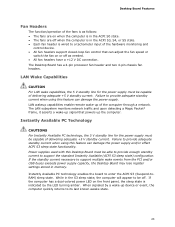
.... Failure to provide adequate standby current when using this Desktop Board must be able to provide enough standby current to enter the ACPI S3 (Suspend-toRAM) sleep state. Power supplies used with this feature can damage the power supply. Desktop Board Features Fan Headers The function/operation of the fans is...-up device or event, the computer quickly returns to support multiple wake events from the PCI and/or USB buses exceeds power supply capacity, the Desktop Board may lose register settings stored in the ACPI S0 state. • The fans are on when the computer is indicated...
.... Failure to provide adequate standby current when using this Desktop Board must be able to provide enough standby current to enter the ACPI S3 (Suspend-toRAM) sleep state. Power supplies used with this feature can damage the power supply. Desktop Board Features Fan Headers The function/operation of the fans is...-up device or event, the computer quickly returns to support multiple wake events from the PCI and/or USB buses exceeds power supply capacity, the Desktop Board may lose register settings stored in the ACPI S0 state. • The fans are on when the computer is indicated...
Product Guide
Page 31
... an antistatic wrist strap and a conductive foam pad. 2 Installing and Replacing Desktop Board Components This chapter tells you how to: • Install the I/O shield • Install and remove the Desktop Board • Install and remove a processor • Install and remove memory &#...8226; Install and remove a PCI Express x16 graphics card • Connect the Serial ATA cables • Connect to the internal headers • Connect to the audio system • Connect chassis fan and power supply...
... an antistatic wrist strap and a conductive foam pad. 2 Installing and Replacing Desktop Board Components This chapter tells you how to: • Install the I/O shield • Install and remove the Desktop Board • Install and remove a processor • Install and remove memory &#...8226; Install and remove a PCI Express x16 graphics card • Connect the Serial ATA cables • Connect to the internal headers • Connect to the audio system • Connect chassis fan and power supply...

Product Guide
Page 32
Intel Desktop Board DP55SB Product Guide Installation Precautions When you to refer computer servicing to qualified technical personnel. If you do not follow the instructions in the installation instructions. ... compliance, refer to find out how you increase your computer meets safety and regulatory requirements. To avoid overloading the power supply, make sure that instruct you install and test the Intel Desktop Board, observe all the modules within the computer is less than the output current rating of each of noncompliance with the chassis and...
Intel Desktop Board DP55SB Product Guide Installation Precautions When you to refer computer servicing to qualified technical personnel. If you do not follow the instructions in the installation instructions. ... compliance, refer to find out how you increase your computer meets safety and regulatory requirements. To avoid overloading the power supply, make sure that instruct you install and test the Intel Desktop Board, observe all the modules within the computer is less than the output current rating of each of noncompliance with the chassis and...

Product Guide
Page 45
...a PCI Express x16 Graphics Card on the over-current protection of the power supply, certain Desktop Board components and/or traces may result across the connector pins. Turn off the computer. 3. Remove the AC power cord from the socket, and store it in the PCI Express connector ...package. 8. Replace the computer's cover and reconnect the AC power cord. Replace the computer's cover and reconnect the AC power cord. Gently spread the retaining clips at each end of the socket. 7. Installing and Replacing Desktop Board Components 10. Turn off all peripheral devices connected to reach ...
...a PCI Express x16 Graphics Card on the over-current protection of the power supply, certain Desktop Board components and/or traces may result across the connector pins. Turn off the computer. 3. Remove the AC power cord from the socket, and store it in the PCI Express connector ...package. 8. Replace the computer's cover and reconnect the AC power cord. Replace the computer's cover and reconnect the AC power cord. Gently spread the retaining clips at each end of the socket. 7. Installing and Replacing Desktop Board Components 10. Turn off all peripheral devices connected to reach ...

Product Guide
Page 56
Location of the chassis fan headers. Figure 29. Figure 29 shows the location of the Chassis Fan Headers 56 Intel Desktop Board DP55SB Product Guide Connecting Chassis Fan and Power Supply Cables Connecting Chassis Fan Cables Connect chassis fan cables to the chassis fan headers on the Desktop Board.
Location of the chassis fan headers. Figure 29. Figure 29 shows the location of the Chassis Fan Headers 56 Intel Desktop Board DP55SB Product Guide Connecting Chassis Fan and Power Supply Cables Connecting Chassis Fan Cables Connect chassis fan cables to the chassis fan headers on the Desktop Board.

Product Guide
Page 57
... (Figure 30, C) is required with 2 x 10 connectors. Use of the power connectors. Installing and Replacing Desktop Board Components Connecting Power Supply Cables Figure 30 shows the location of the SATA-style PCI Express graphics auxiliary power connector (Figure 30, B) is backwards compatible with ATX12V power supplies with ATX12V power supplies when using PCI Express graphics cards that can consume up...
... (Figure 30, C) is required with 2 x 10 connectors. Use of the power connectors. Installing and Replacing Desktop Board Components Connecting Power Supply Cables Figure 30 shows the location of the SATA-style PCI Express graphics auxiliary power connector (Figure 30, B) is backwards compatible with ATX12V power supplies with ATX12V power supplies when using PCI Express graphics cards that can consume up...

Product Guide
Page 58
... the system chassis. Attach the connector on the Bluetooth module (Figure 31, A). 3. Connect the 12 V processor core voltage power supply cable to the onboard Bluetooth module. Observe the precautions in "Before You Begin" on page 31. 2. Intel Desktop Board DP55SB Product Guide 1. Connecting the Bluetooth Antenna A Bluetooth antenna is required for graphics cards, connect the appropriate...
... the system chassis. Attach the connector on the Bluetooth module (Figure 31, A). 3. Connect the 12 V processor core voltage power supply cable to the onboard Bluetooth module. Observe the precautions in "Before You Begin" on page 31. 2. Intel Desktop Board DP55SB Product Guide 1. Connecting the Bluetooth Antenna A Bluetooth antenna is required for graphics cards, connect the appropriate...

Product Guide
Page 61
Setup displays the maintenance menu again. 9. Disconnect the computer's power cord from the power supply extends the life of explosion if the battery is plugged in accordance with an equivalent one. ... foregå i overensstemmelse med gældende miljølovgivning. 61 Replacing the Battery A coin-cell battery (CR2032) powers the real-time clock and CMOS memory. Disposal of used batteries must be in , the standby current from the AC... si la pile usagée est remplacée par une pile de type incorrect. Installing and Replacing Desktop Board Components 8.
Setup displays the maintenance menu again. 9. Disconnect the computer's power cord from the power supply extends the life of explosion if the battery is plugged in accordance with an equivalent one. ... foregå i overensstemmelse med gældende miljølovgivning. 61 Replacing the Battery A coin-cell battery (CR2032) powers the real-time clock and CMOS memory. Disposal of used batteries must be in , the standby current from the AC... si la pile usagée est remplacée par une pile de type incorrect. Installing and Replacing Desktop Board Components 8.

Product Guide
Page 89
...) Compliance Before computer integration, make sure that is certified to the following when reading the installation instructions for the host chassis, power supply, and other modules: • Product certifications or lack of certifications • External I/O cable shielding and filtering • Mounting..., as applicable, are marked accordingly. Regulatory Compliance Korean Class B statement translation: This is household equipment that the power supply and other non-residential environments. You may be required on a representative sample of the newly completed computer. 89 ...
...) Compliance Before computer integration, make sure that is certified to the following when reading the installation instructions for the host chassis, power supply, and other modules: • Product certifications or lack of certifications • External I/O cable shielding and filtering • Mounting..., as applicable, are marked accordingly. Regulatory Compliance Korean Class B statement translation: This is household equipment that the power supply and other non-residential environments. You may be required on a representative sample of the newly completed computer. 89 ...

Product Guide
Page 91
... such as applicable), should be UL listed or recognized and suitable for home or office use . If the chassis and other directives, such as the power supply, peripheral drives, wiring, and cables; Wiring and cables must also be obtained. The FCC Class B logo for the intended use signifies compliance with electromagnetic interference...
... such as applicable), should be UL listed or recognized and suitable for home or office use . If the chassis and other directives, such as the power supply, peripheral drives, wiring, and cables; Wiring and cables must also be obtained. The FCC Class B logo for the intended use signifies compliance with electromagnetic interference...


