Product Guide
Page 3
... and Indicators: information about BIOS error messages and beep codes B Regulatory Compliance: describes the board's adherence to important information. iii Preface This Product Guide gives information about how to prevent damage to hardware or loss of data. The suitability of this Product Guide are used in this manual: CAUTION Cautions warn the user about board layout, component installation, BIOS update, and regulatory requirements for Intel® Desktop Board DP55SB.
... and Indicators: information about BIOS error messages and beep codes B Regulatory Compliance: describes the board's adherence to important information. iii Preface This Product Guide gives information about how to prevent damage to hardware or loss of data. The suitability of this Product Guide are used in this manual: CAUTION Cautions warn the user about board layout, component installation, BIOS update, and regulatory requirements for Intel® Desktop Board DP55SB.
Product Guide
Page 5
... 11 Desktop Board Components 12 Processor ...14 Main Memory...15 Intel® P55 Express Chipset 16 Audio Subsystem 16 LAN Subsystem 16 Bluetooth* Technology Support 17 USB 2.0 Support 18 Serial ATA Support 18 Legacy I/O ...19 Expandability...19 BIOS ...20 Serial ATA Auto Configuration 20 PCI Express* Auto Configuration 20 Security Passwords 20 Hardware Management 21 Hardware Monitoring and Fan Speed Control 21 Intel® Precision Cooling Technology 21 Chassis Intrusion 21 Power Management 22 Software Support 22 ACPI 22 Hardware Support 22 Power Connectors 22 Fan Headers...
... 11 Desktop Board Components 12 Processor ...14 Main Memory...15 Intel® P55 Express Chipset 16 Audio Subsystem 16 LAN Subsystem 16 Bluetooth* Technology Support 17 USB 2.0 Support 18 Serial ATA Support 18 Legacy I/O ...19 Expandability...19 BIOS ...20 Serial ATA Auto Configuration 20 PCI Express* Auto Configuration 20 Security Passwords 20 Hardware Management 21 Hardware Monitoring and Fan Speed Control 21 Intel® Precision Cooling Technology 21 Chassis Intrusion 21 Power Management 22 Software Support 22 ACPI 22 Hardware Support 22 Power Connectors 22 Fan Headers...
Product Guide
Page 6
... Removing a PCI Express x16 Graphics Card 46 Installing Linked PCI Express Graphics Cards 47 Connecting the Serial ATA (SATA) Cables 49 Connecting to the Internal Headers 50 Front Panel Intel HD Audio Header 51 Consumer IR (CIR) Headers 51 Front Panel Header 52 Alternate Front Panel Power LED Header 52 USB 2.0 Headers 53 IEEE 1394a Header 53 Chassis Intrusion Header 54 S/PDIF Header 54 Connecting to the Audio System 55 Connecting Chassis Fan and Power Supply Cables 56 Connecting Chassis Fan Cables 56 Connecting Power Supply Cables 57 Connecting the Bluetooth Antenna 58 Setting...
... Removing a PCI Express x16 Graphics Card 46 Installing Linked PCI Express Graphics Cards 47 Connecting the Serial ATA (SATA) Cables 49 Connecting to the Internal Headers 50 Front Panel Intel HD Audio Header 51 Consumer IR (CIR) Headers 51 Front Panel Header 52 Alternate Front Panel Power LED Header 52 USB 2.0 Headers 53 IEEE 1394a Header 53 Chassis Intrusion Header 54 S/PDIF Header 54 Connecting to the Audio System 55 Connecting Chassis Fan and Power Supply Cables 56 Connecting Chassis Fan Cables 56 Connecting Power Supply Cables 57 Connecting the Bluetooth Antenna 58 Setting...
Product Guide
Page 7
... Socket Cover 37 13. Example Dual Channel Memory Configuration with Three DIMMs 42 21. SATA Drive Activity LED 18 4. Location of the Processor and Voltage Regulator LEDs 27 7. Installing the I/O Shield 33 9. Lift the Load Plate 36 12. Secure the Load Plate in Place 39 17. Internal Headers 50 vii Intel Desktop Board DP55SB Components 12 2. Use DDR3 DIMMs 43 22. Installing Linked PCI Express Graphics Cards 48 26. Contents A Error Messages and Indicators BIOS Error Codes 73 BIOS Error Messages 74 Port 80h POST Codes...
... Socket Cover 37 13. Example Dual Channel Memory Configuration with Three DIMMs 42 21. SATA Drive Activity LED 18 4. Location of the Processor and Voltage Regulator LEDs 27 7. Installing the I/O Shield 33 9. Lift the Load Plate 36 12. Secure the Load Plate in Place 39 17. Internal Headers 50 vii Intel Desktop Board DP55SB Components 12 2. Use DDR3 DIMMs 43 22. Installing Linked PCI Express Graphics Cards 48 26. Contents A Error Messages and Indicators BIOS Error Codes 73 BIOS Error Messages 74 Port 80h POST Codes...
Product Guide
Page 8
... 19. Location of the BIOS Configuration Jumper Block 59 33. Front Panel Intel HD Audio Header Signal Names 51 5. LAN Connector LEDs 17 4. Alternate Front Panel Power LED Header Signal Names 52 9. China RoHS Environmentally Friendly Use Period Mark 86 21. Location of the Chassis Fan Headers 56 30. Port 80h POST Codes 76 18. Intel Desktop Board DP55SB China RoHS Material Self Declaration Table 87 Tables 1. Intel Desktop Board DP55SB Product Guide 28. BIOS Beep Codes 73 15. Front-panel Power LED Blink Codes 73 16. Back Panel Audio Connectors 55...
... 19. Location of the BIOS Configuration Jumper Block 59 33. Front Panel Intel HD Audio Header Signal Names 51 5. LAN Connector LEDs 17 4. Alternate Front Panel Power LED Header Signal Names 52 9. China RoHS Environmentally Friendly Use Period Mark 86 21. Location of the Chassis Fan Headers 56 30. Port 80h POST Codes 76 18. Intel Desktop Board DP55SB China RoHS Material Self Declaration Table 87 Tables 1. Intel Desktop Board DP55SB Product Guide 28. BIOS Beep Codes 73 15. Front-panel Power LED Blink Codes 73 16. Back Panel Audio Connectors 55...
Product Guide
Page 9
... (PCH) Graphics Audio Expansion Capabilities Support for multiple PCI Express* 2.0 graphics cards • Independent multi-streaming 8-channel (7.1) audio and 2-channel audio subsystem, featuring: ― Intel® High Definition (Intel® HD) Audio interface ― Realtek* ALC889 codec • HD Audio front panel header • Onboard 4-pin S/PDIF out connector • Back panel S/PDIF out and in optical connectors • One PCI Express 2.0 x16 port • One PCI Express 2.0 x8 port • Two PCI Express 2.0 x1 ports Legacy I/O Support Peripheral Interfaces RAID Legacy...
... (PCH) Graphics Audio Expansion Capabilities Support for multiple PCI Express* 2.0 graphics cards • Independent multi-streaming 8-channel (7.1) audio and 2-channel audio subsystem, featuring: ― Intel® High Definition (Intel® HD) Audio interface ― Realtek* ALC889 codec • HD Audio front panel header • Onboard 4-pin S/PDIF out connector • Back panel S/PDIF out and in optical connectors • One PCI Express 2.0 x16 port • One PCI Express 2.0 x8 port • Two PCI Express 2.0 x1 ports Legacy I/O Support Peripheral Interfaces RAID Legacy...
Product Guide
Page 10
... symmetrical flash memory device • Support for SMBIOS • Intel® Express BIOS Update Power Management • Support for Advanced Configuration and Power Interface (ACPI) • Suspend to RAM (STR) • Wake on USB, PCI, PCI Express, LAN, CIR, and front panel • ENERGY STAR* capable Hardware Management Hardware monitor with: • Three fan sensing inputs used to monitor fan activity • Intel® Precision Cooling Technology fan speed control • Voltage sensing to detect out of range values 10 Intel Desktop Board DP55SB Product Guide Table...
... symmetrical flash memory device • Support for SMBIOS • Intel® Express BIOS Update Power Management • Support for Advanced Configuration and Power Interface (ACPI) • Suspend to RAM (STR) • Wake on USB, PCI, PCI Express, LAN, CIR, and front panel • ENERGY STAR* capable Hardware Management Hardware monitor with: • Three fan sensing inputs used to monitor fan activity • Intel® Precision Cooling Technology fan speed control • Voltage sensing to detect out of range values 10 Intel Desktop Board DP55SB Product Guide Table...

Product Guide
Page 13
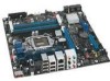
...; Desktop Board Features Table 2. x16 compatible) Front panel audio header S/PDIF header PCI Express 2.0 x1 connector Rear chassis fan header PCI Express 2.0 x1 connector PCI Express 2.0 x16 connector (x8/x16 electrical) Battery Back panel connectors Vertical USB connector 12 V processor core voltage connector (2 x 4 pin) Processor fan header Processor LED Voltage regulator LED Processor socket POST code LED display DDR3 Channel A, DIMM 0 and DIMM 1 sockets DDR3 Channel B, DIMM 0 and DIMM 1 sockets Onboard power button Standby power indicator LED Main power connector (2 x 12 pin) SATA drive...
...; Desktop Board Features Table 2. x16 compatible) Front panel audio header S/PDIF header PCI Express 2.0 x1 connector Rear chassis fan header PCI Express 2.0 x1 connector PCI Express 2.0 x16 connector (x8/x16 electrical) Battery Back panel connectors Vertical USB connector 12 V processor core voltage connector (2 x 4 pin) Processor fan header Processor LED Voltage regulator LED Processor socket POST code LED display DDR3 Channel A, DIMM 0 and DIMM 1 sockets DDR3 Channel B, DIMM 0 and DIMM 1 sockets Onboard power button Standby power indicator LED Main power connector (2 x 12 pin) SATA drive...
Product Guide
Page 19
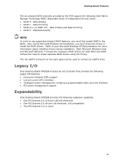
... installation. Legacy I/O Intel Desktop Board DP55SB includes an I/O controller that provides the following legacy I/O features: • Consumer Infrared (CIR) support • Low pin count (LPC) interface • Intelligent power management, including a programmable wake up event interface • PCI power management support Expandability Intel Desktop Board DP55SB provides the following Intel Matrix Storage Technology RAID (Redundant Array of Independent Drives) levels: • RAID 0 - x16 compatible) • Two PCI Express 2.0 x1 ports 19 data mirroring • RAID 0+1 (or RAID...
... installation. Legacy I/O Intel Desktop Board DP55SB includes an I/O controller that provides the following legacy I/O features: • Consumer Infrared (CIR) support • Low pin count (LPC) interface • Intelligent power management, including a programmable wake up event interface • PCI power management support Expandability Intel Desktop Board DP55SB provides the following Intel Matrix Storage Technology RAID (Redundant Array of Independent Drives) levels: • RAID 0 - x16 compatible) • Two PCI Express 2.0 x1 ports 19 data mirroring • RAID 0+1 (or RAID...
Product Guide
Page 20
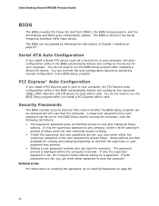
...and user passwords are set , you must enter either password to run the BIOS Setup program after you install a PCI Express add-in the Serial Peripheral Interface (SPI) Flash device. Intel Desktop Board DP55SB Product Guide BIOS The BIOS provides the Power-On Self-Test (POST), the BIOS Setup program, and the PCI Express and SATA auto-configuration utilities. The BIOS can boot the computer. You do not need to access Setup. Serial ATA Auto Configuration If you install a PCI Express add-in card in your computer, the autoconfiguration utility in card. PCI Express* Auto Configuration...
...and user passwords are set , you must enter either password to run the BIOS Setup program after you install a PCI Express add-in the Serial Peripheral Interface (SPI) Flash device. Intel Desktop Board DP55SB Product Guide BIOS The BIOS provides the Power-On Self-Test (POST), the BIOS Setup program, and the PCI Express and SATA auto-configuration utilities. The BIOS can boot the computer. You do not need to access Setup. Serial ATA Auto Configuration If you install a PCI Express add-in card in your computer, the autoconfiguration utility in card. PCI Express* Auto Configuration...

Product Guide
Page 22
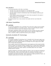
... ACPI-enabled computer receives the correct command, the power supply removes all non-standby voltages. Intel Desktop Board DP55SB Product Guide Power Management Power management is implemented at several levels, including software support through system control. See Figure 30 on or off the computer power through the Advanced Configuration and Power Interface (ACPI) and the following hardware support: • Power connectors • Fan headers • LAN wake capabilities • Instantly Available PC technology (Suspend to RAM) • +5 V standby power indicator LED...
... ACPI-enabled computer receives the correct command, the power supply removes all non-standby voltages. Intel Desktop Board DP55SB Product Guide Power Management Power management is implemented at several levels, including software support through system control. See Figure 30 on or off the computer power through the Advanced Configuration and Power Interface (ACPI) and the following hardware support: • Power connectors • Fan headers • LAN wake capabilities • Instantly Available PC technology (Suspend to RAM) • +5 V standby power indicator LED...
Product Guide
Page 23
... LAN subsystem monitors network traffic and upon detecting a Magic Packet* frame, it asserts a wake-up signal that can damage the power supply and/or effect ACPI S3 sleep state functionality. The Desktop Board has a 4-pin processor fan header and two 4-pin chassis fan headers. Instantly Available PC technology enables the board to a tachometer input of the hardware monitoring and control device. • All fan headers support closed-loop fan control that powers up the computer. If the computer has a dual-colored power LED...
... LAN subsystem monitors network traffic and upon detecting a Magic Packet* frame, it asserts a wake-up signal that can damage the power supply and/or effect ACPI S3 sleep state functionality. The Desktop Board has a 4-pin processor fan header and two 4-pin chassis fan headers. Instantly Available PC technology enables the board to a tachometer input of the hardware monitoring and control device. • All fan headers support closed-loop fan control that powers up the computer. If the computer has a dual-colored power LED...
Product Guide
Page 31
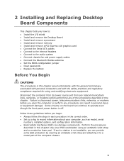
... these guidelines before you how to: • Install the I/O shield • Install and remove the Desktop Board • Install and remove a processor • Install and remove memory • Install and remove a PCI Express x16 graphics card • Connect the Serial ATA cables • Connect to the internal headers • Connect to the audio system • Connect chassis fan and power supply cables • Connect the Bluetooth Module antenna • Set the BIOS configuration jumper • Clear passwords • Replace the battery Before You Begin CAUTIONS The procedures in this...
... these guidelines before you how to: • Install the I/O shield • Install and remove the Desktop Board • Install and remove a processor • Install and remove memory • Install and remove a PCI Express x16 graphics card • Connect the Serial ATA cables • Connect to the internal headers • Connect to the audio system • Connect chassis fan and power supply cables • Connect the Bluetooth Module antenna • Set the BIOS configuration jumper • Clear passwords • Replace the battery Before You Begin CAUTIONS The procedures in this...
Product Guide
Page 44
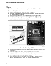
... the small notch at either end of the DIMM with the keys in the socket (see inset in the PCI Express x16 connector, remove the card (see Figure 22). 4. Turn off all peripheral devices connected to the DIMM sockets. Installing a DIMM 5. When the DIMM is installed in Figure 22). 8. If a full length PCI Express graphics card is inserted, push down on the top edge of the DIMM...
... the small notch at either end of the DIMM with the keys in the socket (see inset in the PCI Express x16 connector, remove the card (see Figure 22). 4. Turn off all peripheral devices connected to the DIMM sockets. Installing a DIMM 5. When the DIMM is installed in Figure 22). 8. If a full length PCI Express graphics card is inserted, push down on the top edge of the DIMM...

Product Guide
Page 45
... PCI Express connector before you removed or disconnected to the computer. Reinstall the PCI Express graphics card (see Installing a PCI Express x16 Graphics Card on page 46) to gain access to the DIMM sockets. 6. Observe the precautions in "Before You Begin" on the over-current protection of the power supply, certain Desktop Board components and/or traces may be damaged by the edges, lift it away from the computer. 4. Turn...
... PCI Express connector before you removed or disconnected to the computer. Reinstall the PCI Express graphics card (see Installing a PCI Express x16 Graphics Card on page 46) to gain access to the DIMM sockets. 6. Observe the precautions in "Before You Begin" on the over-current protection of the power supply, certain Desktop Board components and/or traces may be damaged by the edges, lift it away from the computer. 4. Turn...

Product Guide
Page 47
... retention mechanism pin on the connector. 4. Install the first card in "Installing a PCI Express x16 Graphics Card" on page 31. 2. Connect the monitor cable graphics card according to the chassis back panel with the SLI bridge (Figure 25, C) as described in the PCI Express x16 connector as shown. 6. Make sure you use the connector included with the Desktop Board to install linked PCI Express graphics cards such as NVIDIA* SLI* (Scalable Link Interface) cards. Place the second card in the PCI Express x8 connector (Figure...
... retention mechanism pin on the connector. 4. Install the first card in "Installing a PCI Express x16 Graphics Card" on page 31. 2. Connect the monitor cable graphics card according to the chassis back panel with the SLI bridge (Figure 25, C) as described in the PCI Express x16 connector as shown. 6. Make sure you use the connector included with the Desktop Board to install linked PCI Express graphics cards such as NVIDIA* SLI* (Scalable Link Interface) cards. Place the second card in the PCI Express x8 connector (Figure...

Product Guide
Page 60
... (POST) runs, the BIOS displays the Maintenance Menu. Find the configuration jumper block (see Figure 32). 5. Remove the computer cover. 4. Place the jumper on page 31. 2. Observe the precautions in the computer and the configuration jumper block is installed in "Before You Begin" on pins 2-3 as shown below. 6. Intel Desktop Board DP55SB Product Guide Table 13. Turn off all peripheral devices connected to clear passwords. Clearing Passwords This procedure assumes that the board is set to boot. 7. Turn...
... (POST) runs, the BIOS displays the Maintenance Menu. Find the configuration jumper block (see Figure 32). 5. Remove the computer cover. 4. Place the jumper on page 31. 2. Observe the precautions in the computer and the configuration jumper block is installed in "Before You Begin" on pins 2-3 as shown below. 6. Intel Desktop Board DP55SB Product Guide Table 13. Turn off all peripheral devices connected to clear passwords. Clearing Passwords This procedure assumes that the board is set to boot. 7. Turn...
Product Guide
Page 68
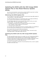
...'s hard drive and without the need to CD. The image uses ISOLINUX* bootloader and automatically launches a script to remove the BIOS configuration jumper. Updating the BIOS with the ISO Image BIOS Update File or the Iflash Memory Update Utility You can be used to create a bootable CD that will update the BIOS. The Iflash BIOS update file contains: • New BIOS file (including the Intel® Management Engine Firmware Image) • Intel® Integrator Toolkit Configuration File (optional) • Intel Flash Memory Update Utility...
...'s hard drive and without the need to CD. The image uses ISOLINUX* bootloader and automatically launches a script to remove the BIOS configuration jumper. Updating the BIOS with the ISO Image BIOS Update File or the Iflash Memory Update Utility You can be used to create a bootable CD that will update the BIOS. The Iflash BIOS update file contains: • New BIOS file (including the Intel® Management Engine Firmware Image) • Intel® Integrator Toolkit Configuration File (optional) • Intel Flash Memory Update Utility...

Product Guide
Page 70
... updating the Intel Desktop Board BIOS or recovering from the USB device and manually update the BIOS. Intel Desktop Board DP55SB Product Guide CAUTION Do not interrupt the process or the system may not function properly. 1. Uncompress the BIOS update file and copy the .BIO file, IFLASH.EXE, and .ITK file (optional) to http://support.intel.com/support/motherboards/desktop/sb/CS-022312.htm 70 Configure the BIOS or use the F10 option during POST to boot to BIOS size and recovery requirements, a CD-R with the .BIO file...
... updating the Intel Desktop Board BIOS or recovering from the USB device and manually update the BIOS. Intel Desktop Board DP55SB Product Guide CAUTION Do not interrupt the process or the system may not function properly. 1. Uncompress the BIOS update file and copy the .BIO file, IFLASH.EXE, and .ITK file (optional) to http://support.intel.com/support/motherboards/desktop/sb/CS-022312.htm 70 Configure the BIOS or use the F10 option during POST to boot to BIOS size and recovery requirements, a CD-R with the .BIO file...

Product Guide
Page 72
...the Intel Matrix Storage Console software via the Intel Express Installer CD included with your Desktop Board or after downloading it from the Windows installation CD. 2. Begin Windows Setup by booting from the Internet at http://support.intel.com/support/motherboards/desktop/. Intel Desktop Board DP55SB Product Guide Loading the Intel Matrix Storage Technology RAID Drivers and Software (Required for information on supported USB floppy disk drives. Setting Up a "RAID Ready" System The Intel Matrix Storage Technology Console software offers the flexibility to upgrade from a single Serial...
...the Intel Matrix Storage Console software via the Intel Express Installer CD included with your Desktop Board or after downloading it from the Windows installation CD. 2. Begin Windows Setup by booting from the Internet at http://support.intel.com/support/motherboards/desktop/. Intel Desktop Board DP55SB Product Guide Loading the Intel Matrix Storage Technology RAID Drivers and Software (Required for information on supported USB floppy disk drives. Setting Up a "RAID Ready" System The Intel Matrix Storage Technology Console software offers the flexibility to upgrade from a single Serial...


