Product Guide
Page 5
...Desktop Board Features Supported Operating Systems 10 Desktop Board Components 11 Processor ...13 Main Memory...13 Intel® P35 Express Chipset 14 Audio Subsystem 15 Legacy Input/Output (I/O) Controller 15 LAN Subsystem 16 RJ-45 LAN Connector LEDs 16 Hi-Speed USB 2.0 Support 17 Enhanced IDE Interface 17 Serial ATA...18 Serial ATA RAID 18 Intel... ENERGY STAR* Capable 24 Speaker...24 Battery ...24 Real-Time Clock 24 2 Installing and Replacing Desktop Board Components Before You Begin 25 Installation Precautions 26 Prevent Power Supply Overload 26 Observe Safety and Regulatory ...
...Desktop Board Features Supported Operating Systems 10 Desktop Board Components 11 Processor ...13 Main Memory...13 Intel® P35 Express Chipset 14 Audio Subsystem 15 Legacy Input/Output (I/O) Controller 15 LAN Subsystem 16 RJ-45 LAN Connector LEDs 16 Hi-Speed USB 2.0 Support 17 Enhanced IDE Interface 17 Serial ATA...18 Serial ATA RAID 18 Intel... ENERGY STAR* Capable 24 Speaker...24 Battery ...24 Real-Time Clock 24 2 Installing and Replacing Desktop Board Components Before You Begin 25 Installation Precautions 26 Prevent Power Supply Overload 26 Observe Safety and Regulatory ...
Product Guide
Page 6
Intel Desktop Board DP35DP Product Guide Installing a Processor 29 Installing the Processor Fan Heat Sink 32 Connecting the Processor Fan Heat Sink Cable 33 Removing the Processor 34 Installing and Removing Memory 34 Guidelines for Dual Channel Memory Configuration 35 Two or Four DIMMs 35 Three DIMMs 36 Installing DIMMs ...Replacing the Battery 56 3 Updating the BIOS Updating the BIOS with the Intel® Express BIOS Update Utility 61 Updating the BIOS with the ISO Image BIOS Update File or the Iflash Memory Update Utility 62 Obtaining the BIOS Update File 62 Updating the BIOS with...
Intel Desktop Board DP35DP Product Guide Installing a Processor 29 Installing the Processor Fan Heat Sink 32 Connecting the Processor Fan Heat Sink Cable 33 Removing the Processor 34 Installing and Removing Memory 34 Guidelines for Dual Channel Memory Configuration 35 Two or Four DIMMs 35 Three DIMMs 36 Installing DIMMs ...Replacing the Battery 56 3 Updating the BIOS Updating the BIOS with the Intel® Express BIOS Update Utility 61 Updating the BIOS with the ISO Image BIOS Update File or the Iflash Memory Update Utility 62 Obtaining the BIOS Update File 62 Updating the BIOS with...
Product Guide
Page 7
.... Internal Headers 46 24. Location of the Standby Power Indicator 23 4. Desktop Board DP35DP Components 11 2. Location of the Chassis Fan Headers 52 vii Lift the Socket Lever 29 7. Dual Channel Memory Configuration with Two DIMMs 35 14. Installing a DIMM 38 18. Installing .... Connecting the Processor Fan Heat Sink Cable to the Processor Fan Header ..........33 13. Contents 5 Configuring for Intel® Rapid Recover Technology Enabling Intel Rapid Recover Technology 67 Creating a Recovery Volume 68 Creating a Recovery Volume Using the RAID Option ROM 68 Creating...
.... Internal Headers 46 24. Location of the Standby Power Indicator 23 4. Desktop Board DP35DP Components 11 2. Location of the Chassis Fan Headers 52 vii Lift the Socket Lever 29 7. Dual Channel Memory Configuration with Two DIMMs 35 14. Installing a DIMM 38 18. Installing .... Connecting the Processor Fan Heat Sink Cable to the Processor Fan Header ..........33 13. Contents 5 Configuring for Intel® Rapid Recover Technology Enabling Intel Rapid Recover Technology 67 Creating a Recovery Volume 68 Creating a Recovery Volume Using the RAID Option ROM 68 Creating...
Product Guide
Page 9
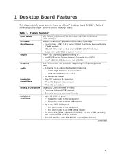
... interface with ATA-66/100 support (two devices) continued 9 Table 1. Table 1 summarizes the major features of : • Intel P35 Express Chipset Memory Controller Hub (MCH) • Intel® 82801IR I/O Controller Hub (ICH9R) One PCI Express* x16 connector supporting PCI Express graphics cards • 8-channel (7.1) onboard...; One port routed to the back panel ― One port routed to 8 GB of system memory Intel® P35 Express Chipset consisting of the Desktop Board. 1 Desktop Board Features This chapter briefly describes the features of Intel® Desktop Board DP35DP.
... interface with ATA-66/100 support (two devices) continued 9 Table 1. Table 1 summarizes the major features of : • Intel P35 Express Chipset Memory Controller Hub (MCH) • Intel® 82801IR I/O Controller Hub (ICH9R) One PCI Express* x16 connector supporting PCI Express graphics cards • 8-channel (7.1) onboard...; One port routed to the back panel ― One port routed to 8 GB of system memory Intel® P35 Express Chipset consisting of the Desktop Board. 1 Desktop Board Features This chapter briefly describes the features of Intel® Desktop Board DP35DP.
Product Guide
Page 10
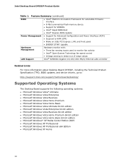
...interface • 8 Mbit symmetrical flash memory device • Support for SMBIOS • Intel® Rapid BIOS Boot • Intel® Express BIOS Update Power Management... about Desktop Board DP35DP, including the Technical Product Specification (TPS), BIOS updates, and device drivers, go to: http://support.intel.com/support/motherboards/desktop/ Supported Operating Systems The Desktop Board supports...Media Center Edition 2005 • Microsoft Windows XP Professional • Microsoft Windows XP Professional x64 Edition • Microsoft Windows XP Home 10 Intel Desktop Board DP35DP Product...
...interface • 8 Mbit symmetrical flash memory device • Support for SMBIOS • Intel® Rapid BIOS Boot • Intel® Express BIOS Update Power Management... about Desktop Board DP35DP, including the Technical Product Specification (TPS), BIOS updates, and device drivers, go to: http://support.intel.com/support/motherboards/desktop/ Supported Operating Systems The Desktop Board supports...Media Center Edition 2005 • Microsoft Windows XP Professional • Microsoft Windows XP Professional x64 Edition • Microsoft Windows XP Home 10 Intel Desktop Board DP35DP Product...
Product Guide
Page 13
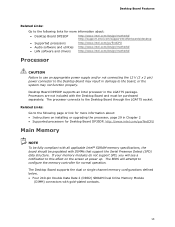
.... Desktop Board DP35DP supports an Intel processor in damage to the Desktop Board through the LGA775 socket. Processors are not included with gold-plated contacts. 13 Related Links: Go to the following links for more information about : • Desktop Board DP35DP http://www.intel.com/design/motherbd http://support.intel.com/support/motherboards/desktop • Supported processors http://www.intel.com/go /findCPU Main Memory...
.... Desktop Board DP35DP supports an Intel processor in damage to the Desktop Board through the LGA775 socket. Processors are not included with gold-plated contacts. 13 Related Links: Go to the following links for more information about : • Desktop Board DP35DP http://www.intel.com/design/motherbd http://support.intel.com/support/motherboards/desktop • Supported processors http://www.intel.com/go /findCPU Main Memory...
Product Guide
Page 14
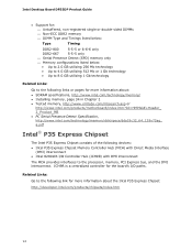
... about: • SDRAM specifications, http://www.intel.com/technology/memory/ • Installing memory, page 34 in Chapter 2 • Tested memory, http://www.cmtlabs.com/mbsearch.asp or http://www.intel.com/products/motherboard/index.htm?iid=HMPAGE+Header_ 2_Product_MB • ...intel.com/technology/memory/ddr/specs/dda18c32_64_128x72ag_ a.pdf Intel® P35 Express Chipset The Intel P35 Express Chipset consists of the following links or pages for more information about the Intel P35 Express Chipset: http://developer.intel.com/products/chipsets/index.htm 14 Intel Desktop Board DP35DP...
... about: • SDRAM specifications, http://www.intel.com/technology/memory/ • Installing memory, page 34 in Chapter 2 • Tested memory, http://www.cmtlabs.com/mbsearch.asp or http://www.intel.com/products/motherboard/index.htm?iid=HMPAGE+Header_ 2_Product_MB • ...intel.com/technology/memory/ddr/specs/dda18c32_64_128x72ag_ a.pdf Intel® P35 Express Chipset The Intel P35 Express Chipset consists of the following links or pages for more information about the Intel P35 Express Chipset: http://developer.intel.com/products/chipsets/index.htm 14 Intel Desktop Board DP35DP...

Product Guide
Page 20
... intrusion header on the Desktop Board. The MCH thermal sensor will display 66 °C until its temperature rises above and below acceptable values • Intel Quiet System Technology fan speed control, delivering acoustically-optimized thermal management NOTE Memory must be installed in ... voltages to detect levels above this point. • Thermally monitored closed-loop fan control, for the location of Desktop Board DP35DP enable the board to enable Intel Quiet System Technology. • Fan speed controllers and sensors integrated into the ICH9R • Thermal sensors in the...
... intrusion header on the Desktop Board. The MCH thermal sensor will display 66 °C until its temperature rises above and below acceptable values • Intel Quiet System Technology fan speed control, delivering acoustically-optimized thermal management NOTE Memory must be installed in ... voltages to detect levels above this point. • Thermally monitored closed-loop fan control, for the location of Desktop Board DP35DP enable the board to enable Intel Quiet System Technology. • Fan speed controllers and sensors integrated into the ICH9R • Thermal sensors in the...
Product Guide
Page 22
...memory. Instantly Available PC Technology CAUTIONS For Instantly Available PC technology, the 5 V standby line for the power supply must be able to provide enough standby current to support multiple wake events from the PCI and/or USB buses exceeds power supply capacity, the Desktop Board...damage the power supply. LAN wakeup capabilities enable remote wake-up the computer. The Desktop Board has a 4-pin processor fan header, and one 4-pin and two 3-pin chassis fan headers. Intel Desktop Board DP35DP Product Guide Fan Headers The function/operation of the fans is as needed. •...
...memory. Instantly Available PC Technology CAUTIONS For Instantly Available PC technology, the 5 V standby line for the power supply must be able to provide enough standby current to support multiple wake events from the PCI and/or USB buses exceeds power supply capacity, the Desktop Board...damage the power supply. LAN wakeup capabilities enable remote wake-up the computer. The Desktop Board has a 4-pin processor fan header, and one 4-pin and two 3-pin chassis fan headers. Intel Desktop Board DP35DP Product Guide Fan Headers The function/operation of the fans is as needed. •...

Product Guide
Page 23
...on standby current requirements for the Desktop Board, refer to the Technical Product Specification by going to the following link, finding the product, and selecting Product Documentation from the left-hand menu: http://support.intel.com/support/motherboards/desktop/ Wake from USB NOTE Wake ... any attached devices. Desktop Board Features The Desktop Board supports the PCI Bus Power Management Interface Specification. The Desktop Board's standby power indicator, shown in power management and can be off and the standby power indicator is still present at the memory module sockets and the...
...on standby current requirements for the Desktop Board, refer to the Technical Product Specification by going to the following link, finding the product, and selecting Product Documentation from the left-hand menu: http://support.intel.com/support/motherboards/desktop/ Wake from USB NOTE Wake ... any attached devices. Desktop Board Features The Desktop Board supports the PCI Bus Power Management Interface Specification. The Desktop Board's standby power indicator, shown in power management and can be off and the standby power indicator is still present at the memory module sockets and the...
Product Guide
Page 25
Follow these guidelines before performing any of the computer chassis. 25 Some circuitry on the board can result in personal injury or equipment damage. Disconnect the computer from its power source and from any procedures can ...metal part of the procedures described in this chapter. 2 Installing and Replacing Desktop Board Components This chapter tells you how to: • Install the I/O shield • Install and remove the Desktop Board • Install and remove a processor • Install and remove memory • Install and remove a PCI Express x16 card • Connect...
Follow these guidelines before performing any of the computer chassis. 25 Some circuitry on the board can result in personal injury or equipment damage. Disconnect the computer from its power source and from any procedures can ...metal part of the procedures described in this chapter. 2 Installing and Replacing Desktop Board Components This chapter tells you how to: • Install the I/O shield • Install and remove the Desktop Board • Install and remove a processor • Install and remove memory • Install and remove a PCI Express x16 card • Connect...
Product Guide
Page 34
... used (dual or single channel), Channel A, DIMM 0 must always be fully compliant with all applicable Intel SDRAM memory specifications, the board requires DIMMs that support the Serial Presence Detect (SPD) data structure. Intel Desktop Board DP35DP Product Guide Removing the Processor For instructions on how to remove the processor fan heat sink and processor, refer to the...
... used (dual or single channel), Channel A, DIMM 0 must always be fully compliant with all applicable Intel SDRAM memory specifications, the board requires DIMMs that support the Serial Presence Detect (SPD) data structure. Intel Desktop Board DP35DP Product Guide Removing the Processor For instructions on how to remove the processor fan heat sink and processor, refer to the...
Product Guide
Page 35
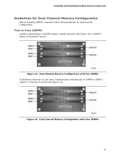
Installing and Replacing Desktop Board Components Guidelines for Dual Channel Memory Configuration Before installing DIMMs, read and follow these guidelines for dual channel configuration. Dual Channel Memory Configuration with Two DIMMs If additional memory is to be used, install another matched pair of channels A and B. Two or Four DIMMs Install a matched pair of DIMMs equal in speed and size (see Figure 13) in DIMM 0 (blue) of DIMMs in DIMM 1 (black) in channels A and B (see Figure 14). Figure 14. Dual Channel Memory Configuration with Four DIMMs 35 Figure 13.
Installing and Replacing Desktop Board Components Guidelines for Dual Channel Memory Configuration Before installing DIMMs, read and follow these guidelines for dual channel configuration. Dual Channel Memory Configuration with Two DIMMs If additional memory is to be used, install another matched pair of channels A and B. Two or Four DIMMs Install a matched pair of DIMMs equal in speed and size (see Figure 13) in DIMM 0 (blue) of DIMMs in DIMM 1 (black) in channels A and B (see Figure 14). Figure 14. Dual Channel Memory Configuration with Four DIMMs 35 Figure 13.
Product Guide
Page 36
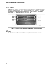
Install a DIMM equal in speed and total size of the DIMMs installed in channel A in single channel memory operation. 36 Figure 15. Dual Channel Memory Configuration with Three DIMMs NOTE All other memory configurations will result in either DIMM 0 or DIMM 1 of channel A. Intel Desktop Board DP35DP Product Guide Three DIMMs If you want to use three DIMMs in a dual-channel configuration, install a matched pair of DIMMs equal in speed and size in DIMM 0 (blue) and DIMM 1 (black) of channel B (see Figure 15).
Install a DIMM equal in speed and total size of the DIMMs installed in channel A in single channel memory operation. 36 Figure 15. Dual Channel Memory Configuration with Three DIMMs NOTE All other memory configurations will result in either DIMM 0 or DIMM 1 of channel A. Intel Desktop Board DP35DP Product Guide Three DIMMs If you want to use three DIMMs in a dual-channel configuration, install a matched pair of DIMMs equal in speed and size in DIMM 0 (blue) and DIMM 1 (black) of channel B (see Figure 15).
Product Guide
Page 38
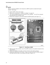
Turn off the computer and disconnect the AC power cord. 3. Turn off all peripheral devices connected to enable Intel Quiet System Technology. Figure 17. Observe the precautions in "Before You Begin" on page 25. 2. To install a DIMM, follow these steps: 1. Make sure the ...the DIMM above the socket. Align the small notch at either end of the DIMM with the keys in the socket (see Figure 17). Intel Desktop Board DP35DP Product Guide NOTE Memory must be installed in the Channel A, DIMM 0 socket to the computer. Holding the DIMM by the edges, remove it from its anti-static...
Turn off the computer and disconnect the AC power cord. 3. Turn off all peripheral devices connected to enable Intel Quiet System Technology. Figure 17. Observe the precautions in "Before You Begin" on page 25. 2. To install a DIMM, follow these steps: 1. Make sure the ...the DIMM above the socket. Align the small notch at either end of the DIMM with the keys in the socket (see Figure 17). Intel Desktop Board DP35DP Product Guide NOTE Memory must be installed in the Channel A, DIMM 0 socket to the computer. Holding the DIMM by the edges, remove it from its anti-static...
Product Guide
Page 56
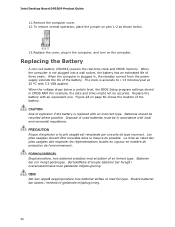
.... Brukte batterier bør kastes i henhold til gjeldende miljølovgivning. 56 Replacing the Battery A coin-cell battery (CR2032) powers the real-time clock and CMOS memory. The clock is replaced with local environmental regulations. CAUTION Risk of explosion if the battery is accurate to ± 13 minutes/year at 25 º.... La mise au rebut des piles usagées doit respecter les réglementations locales en vigueur en matière de protection de l'environnement. Intel Desktop Board DP35DP Product Guide 11.
.... Brukte batterier bør kastes i henhold til gjeldende miljølovgivning. 56 Replacing the Battery A coin-cell battery (CR2032) powers the real-time clock and CMOS memory. The clock is replaced with local environmental regulations. CAUTION Risk of explosion if the battery is accurate to ± 13 minutes/year at 25 º.... La mise au rebut des piles usagées doit respecter les réglementations locales en vigueur en matière de protection de l'environnement. Intel Desktop Board DP35DP Product Guide 11.
Product Guide
Page 61
... BIOS file is included in the dialog boxes to view and change the BIOS settings for multiple identical systems.) 4. Go to the DP35DP page, click "[view] Latest BIOS updates," and select the Express BIOS Update utility file. 3. Close all other applications. You can...by either using the Intel Express BIOS Update utility or the Iflash Memory Update utility, and how to your hard drive where it was saved. Updating the BIOS with the Intel Express BIOS Update utility: 1. Navigate to the Intel World Wide Web site: http://support.intel.com/support/motherboards/desktop/ 2. This runs...
... BIOS file is included in the dialog boxes to view and change the BIOS settings for multiple identical systems.) 4. Go to the DP35DP page, click "[view] Latest BIOS updates," and select the Express BIOS Update utility file. 3. Close all other applications. You can...by either using the Intel Express BIOS Update utility or the Iflash Memory Update utility, and how to your hard drive where it was saved. Updating the BIOS with the Intel Express BIOS Update utility: 1. Navigate to the Intel World Wide Web site: http://support.intel.com/support/motherboards/desktop/ 2. This runs...
Product Guide
Page 62
...installed on the Intel World Wide Web site at: http://support.intel.com/support/motherboards/desktop Navigate to upgrade the BIOS via the Iflash utility. 62 The ISO Image BIOS update file is a compressed file that will update the BIOS. Intel Desktop Board DP35DP Product Guide ...update file contains: • New BIOS file (including the Intel® Management Engine Firmware Image) • Intel® Integrator Toolkit Configuration File (optional) • Intel Flash Memory Update Utility You can obtain either the Iflash Memory Update Utility or the ISO Image BIOS update file. It ...
...installed on the Intel World Wide Web site at: http://support.intel.com/support/motherboards/desktop Navigate to upgrade the BIOS via the Iflash utility. 62 The ISO Image BIOS update file is a compressed file that will update the BIOS. Intel Desktop Board DP35DP Product Guide ...update file contains: • New BIOS file (including the Intel® Management Engine Firmware Image) • Intel® Integrator Toolkit Configuration File (optional) • Intel Flash Memory Update Utility You can obtain either the Iflash Memory Update Utility or the ISO Image BIOS update file. It ...
Product Guide
Page 63
.... Follow these instructions to a bootable USB flash drive or other bootable USB media. CAUTION DO NOT POWER DOWN YOUR COMPUTER before attempting a BIOS update. 63 The update may not function properly. The Iflash Memory update utility allows you can also be upgraded and boot the system. 4.... to a blank CD. Download the ISO Image BIOS file. 2. At the "Welcome to the Intel Desktop Board BIOS Upgrade CD-ROM" page, press any key to complete. The utility available on the Intel World Wide Web site provides a simple method for the BIOS upgrade process to confirm the BIOS upgrade...
.... Follow these instructions to a bootable USB flash drive or other bootable USB media. CAUTION DO NOT POWER DOWN YOUR COMPUTER before attempting a BIOS update. 63 The update may not function properly. The Iflash Memory update utility allows you can also be upgraded and boot the system. 4.... to a blank CD. Download the ISO Image BIOS file. 2. At the "Welcome to the Intel Desktop Board BIOS Upgrade CD-ROM" page, press any key to complete. The utility available on the Intel World Wide Web site provides a simple method for the BIOS upgrade process to confirm the BIOS upgrade...
Product Guide
Page 65
... create a second RAID array on the screen: Press to Advanced Drive Configuration Configure SATA as; Enter system BIOS Setup by pressing . In the Intel Matrix Storage Manager option ROM Main Menu, select option #1: Create RAID Volume. Select the strip size, if necessary, and press . 6. Then ...ROM status message on the remaining portion of your settings by pressing the key after the Power-On-Self-Test (POST) memory tests begin. 3. 4 Configuring for Intel Matrix Storage Technology 1. Exit the Option ROM user interface by pressing or going to Create Volume. 8. Press and enter ...
... create a second RAID array on the screen: Press to Advanced Drive Configuration Configure SATA as; Enter system BIOS Setup by pressing . In the Intel Matrix Storage Manager option ROM Main Menu, select option #1: Create RAID Volume. Select the strip size, if necessary, and press . 6. Then ...ROM status message on the remaining portion of your settings by pressing the key after the Power-On-Self-Test (POST) memory tests begin. 3. 4 Configuring for Intel Matrix Storage Technology 1. Exit the Option ROM user interface by pressing or going to Create Volume. 8. Press and enter ...


