Product Guide
Page 3
...: 1 Desktop Board Features: a summary of product features 2 Installing and Replacing Desktop Board Components: instructions on how to install the Desktop Board and other hardware components 3 Updating the BIOS: instructions on how to update the BIOS 4 Configuring for RAID (Intel® Matrix Storage Technology): information about configuring your system for RAID 5 Configuring for Intel® Rapid Recover Technology: information about configuring your system for general audiences. Preface This Product Guide gives information about board layout, component installation, BIOS update, and...
...: 1 Desktop Board Features: a summary of product features 2 Installing and Replacing Desktop Board Components: instructions on how to install the Desktop Board and other hardware components 3 Updating the BIOS: instructions on how to update the BIOS 4 Configuring for RAID (Intel® Matrix Storage Technology): information about configuring your system for RAID 5 Configuring for Intel® Rapid Recover Technology: information about configuring your system for general audiences. Preface This Product Guide gives information about board layout, component installation, BIOS update, and...
Product Guide
Page 4
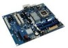
...; Intel Desktop Board DP35DP • I/O shield • One ATA-66/100 cable • Two locking Serial ATA (SATA) cables • External SATA (eSATA) Port adapter bracket • Quick Reference poster • Configuration and battery caution statement labels • Intel® Matrix Storage Technology Raid Driver diskette • Intel® Express Installer Driver and Software DVD-ROM iv NOTE Notes call attention to hardware or loss of some common terms used in the product guide. Intel Desktop Board DP35DP Product Guide Conventions...
...; Intel Desktop Board DP35DP • I/O shield • One ATA-66/100 cable • Two locking Serial ATA (SATA) cables • External SATA (eSATA) Port adapter bracket • Quick Reference poster • Configuration and battery caution statement labels • Intel® Matrix Storage Technology Raid Driver diskette • Intel® Express Installer Driver and Software DVD-ROM iv NOTE Notes call attention to hardware or loss of some common terms used in the product guide. Intel Desktop Board DP35DP Product Guide Conventions...
Product Guide
Page 6
...48 Connecting to the Serial Port Header 49 Connecting to the Chassis Intrusion Header 49 Connecting to the Alternate Front Panel Power LED Header 49 Connecting to the Front Panel Header 50 Connecting to the USB 2.0 Headers 50 Connecting to the Flexible Audio System 51 Connecting Chassis Fan and Power Supply Cables 52 Connecting Chassis Fan Cables 52 Connecting Supply Power Cables 53 Setting the BIOS Configuration Jumper 54 Clearing Passwords 55 Replacing the Battery 56 3 Updating the BIOS Updating the BIOS with the Intel® Express BIOS Update Utility 61 Updating the BIOS with...
...48 Connecting to the Serial Port Header 49 Connecting to the Chassis Intrusion Header 49 Connecting to the Alternate Front Panel Power LED Header 49 Connecting to the Front Panel Header 50 Connecting to the USB 2.0 Headers 50 Connecting to the Flexible Audio System 51 Connecting Chassis Fan and Power Supply Cables 52 Connecting Chassis Fan Cables 52 Connecting Supply Power Cables 53 Setting the BIOS Configuration Jumper 54 Clearing Passwords 55 Replacing the Battery 56 3 Updating the BIOS Updating the BIOS with the Intel® Express BIOS Update Utility 61 Updating the BIOS with...
Product Guide
Page 7
... Close the Load Plate 32 12. Desktop Board DP35DP Components 11 2. Location of the Chassis Fan Headers 52 vii Back Panel Audio Connectors 51 25. Remove the Protective Socket Cover 30 9. Installing a DIMM 38 18. Installing the I/O Shield 27 5. Connecting the Processor Fan Heat Sink Cable to the Processor Fan Header ..........33 13. Installing a PCI Express x16 Card 40 19. Contents 5 Configuring for Intel® Rapid Recover Technology Enabling Intel Rapid Recover Technology 67 Creating a Recovery Volume 68 Creating a Recovery Volume Using the RAID Option ROM 68...
... Close the Load Plate 32 12. Desktop Board DP35DP Components 11 2. Location of the Chassis Fan Headers 52 vii Back Panel Audio Connectors 51 25. Remove the Protective Socket Cover 30 9. Installing a DIMM 38 18. Installing the I/O Shield 27 5. Connecting the Processor Fan Heat Sink Cable to the Processor Fan Header ..........33 13. Installing a PCI Express x16 Card 40 19. Contents 5 Configuring for Intel® Rapid Recover Technology Enabling Intel Rapid Recover Technology 67 Creating a Recovery Volume 68 Creating a Recovery Volume Using the RAID Option ROM 68...
Product Guide
Page 8
... 9. Beep Codes 71 16. Lead-Free Board Markings 79 19. Product Certification Markings 82 viii Jumper Settings for the BIOS Setup Program Modes 55 15. Connecting Power Supply Cables 53 27. HD Audio Link Header Signal Names 47 5. Safety Regulations 73 18. EMC Regulations 80 20. Serial Port Header Signal Names 49 10. Alternate Front Panel Power LED Header 49 12. Front Panel Intel High Definition Audio Header Signal Names 47 7. Location of the BIOS Configuration Jumper Block 54 28. Desktop Board DP35DP Components...
... 9. Beep Codes 71 16. Lead-Free Board Markings 79 19. Product Certification Markings 82 viii Jumper Settings for the BIOS Setup Program Modes 55 15. Connecting Power Supply Cables 53 27. HD Audio Link Header Signal Names 47 5. Safety Regulations 73 18. EMC Regulations 80 20. Serial Port Header Signal Names 49 10. Alternate Front Panel Power LED Header 49 12. Front Panel Intel High Definition Audio Header Signal Names 47 7. Location of the BIOS Configuration Jumper Block 54 28. Desktop Board DP35DP Components...
Product Guide
Page 9
...; processor in the LGA775 package • Four 240-pin, DDR2 1.8 V (only) SDRAM Dual Inline Memory Module (DIMM) sockets • 800/667 MHz single or dual channel DDR2 SDRAM interface • Support for up to 8 GB of system memory Intel® P35 Express Chipset consisting of: • Intel P35 Express Chipset Memory Controller Hub (MCH) • Intel® 82801IR I/O Controller Hub (ICH9R) One PCI Express* x16 connector supporting PCI Express graphics cards • 8-channel (7.1) onboard subsystem, featuring: ― Intel® High Definition Audio...
...; processor in the LGA775 package • Four 240-pin, DDR2 1.8 V (only) SDRAM Dual Inline Memory Module (DIMM) sockets • 800/667 MHz single or dual channel DDR2 SDRAM interface • Support for up to 8 GB of system memory Intel® P35 Express Chipset consisting of: • Intel P35 Express Chipset Memory Controller Hub (MCH) • Intel® 82801IR I/O Controller Hub (ICH9R) One PCI Express* x16 connector supporting PCI Express graphics cards • 8-channel (7.1) onboard subsystem, featuring: ― Intel® High Definition Audio...
Product Guide
Page 10
... fan sensing inputs used to monitor fan activity • Intel® Quiet System Technology fan speed control • Voltage sensing to detect out of range values LAN Support Intel® 82566DC Gigabit (10/100/1000 Mb/s) Ethernet LAN controller Related Links: For more information about Desktop Board DP35DP, including the Technical Product Specification (TPS), BIOS updates, and device drivers, go to: http://support.intel.com/support/motherboards/desktop/ Supported Operating Systems The Desktop Board supports the following operating systems: • Microsoft Windows Vista...
... fan sensing inputs used to monitor fan activity • Intel® Quiet System Technology fan speed control • Voltage sensing to detect out of range values LAN Support Intel® 82566DC Gigabit (10/100/1000 Mb/s) Ethernet LAN controller Related Links: For more information about Desktop Board DP35DP, including the Technical Product Specification (TPS), BIOS updates, and device drivers, go to: http://support.intel.com/support/motherboards/desktop/ Supported Operating Systems The Desktop Board supports the following operating systems: • Microsoft Windows Vista...
Product Guide
Page 13
...; Audio software and utilities http://www.intel.com/design/motherbd • LAN software and drivers http://www.intel.com/design/motherbd Processor CAUTION Failure to use an appropriate power supply and/or not connecting the 12 V (2 x 2 pin) power connector to the Desktop Board may not function properly. If your memory modules do not support SPD, you will attempt to configure the memory controller for more information about : • Instructions on the screen at power up. The Desktop Board supports the dual...
...; Audio software and utilities http://www.intel.com/design/motherbd • LAN software and drivers http://www.intel.com/design/motherbd Processor CAUTION Failure to use an appropriate power supply and/or not connecting the 12 V (2 x 2 pin) power connector to the Desktop Board may not function properly. If your memory modules do not support SPD, you will attempt to configure the memory controller for more information about : • Instructions on the screen at power up. The Desktop Board supports the dual...
Product Guide
Page 16
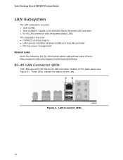
... Intel Desktop Board DP35DP Product Guide LAN Subsystem The LAN subsystem includes: • Intel ICH9R • Intel 82566DC Gigabit (10/100/1000 Mb/s) Ethernet LAN controller • RJ-45 LAN connector with integrated status LEDs The subsystem features: • CSMA/CD protocol engine • LAN connect interface between ICH9R and the LAN controller • PCI bus power management Related Links: Go to the following link for information about LAN software and drivers: http://support.intel.com/support/motherboards/desktop...
... Intel Desktop Board DP35DP Product Guide LAN Subsystem The LAN subsystem includes: • Intel ICH9R • Intel 82566DC Gigabit (10/100/1000 Mb/s) Ethernet LAN controller • RJ-45 LAN connector with integrated status LEDs The subsystem features: • CSMA/CD protocol engine • LAN connect interface between ICH9R and the LAN controller • PCI bus power management Related Links: Go to the following link for information about LAN software and drivers: http://support.intel.com/support/motherboards/desktop...
Product Guide
Page 18
... striping and mirroring • RAID 5 - Intel® Rapid Recover Technology Intel® Rapid Recover Technology enables fast and easy recovery of your primary or master drive onto a second hard drive, the recovery drive. Intel Desktop Board DP35DP Product Guide Serial ATA The Desktop Board supports six Serial ATA channels (3.0 Gb/s) via any standard SATA or eSATA connection. Serial ATA RAID The ICH9R supports the following expansion slots: • Three PCI Express x1 connectors • One PCI Express x16 connector • Three PCI bus connectors 18 distributed parity For...
... striping and mirroring • RAID 5 - Intel® Rapid Recover Technology Intel® Rapid Recover Technology enables fast and easy recovery of your primary or master drive onto a second hard drive, the recovery drive. Intel Desktop Board DP35DP Product Guide Serial ATA The Desktop Board supports six Serial ATA channels (3.0 Gb/s) via any standard SATA or eSATA connection. Serial ATA RAID The ICH9R supports the following expansion slots: • Three PCI Express x1 connectors • One PCI Express x16 connector • Three PCI bus connectors 18 distributed parity For...
Product Guide
Page 19
... set for the BIOS Setup and for a password. The BIOS is booted. The password prompt is displayed before the computer is stored in Chapter 3. The BIOS can boot the computer. You can enter either the supervisor password or the user password to run the BIOS Setup program after you must enter either password to view and change all Setup options. Desktop Board Features BIOS The BIOS provides the Power-On Self-Test (POST), the BIOS Setup program, the PCI/PCI Express and IDE auto-configuration utilities...
... set for the BIOS Setup and for a password. The BIOS is booted. The password prompt is displayed before the computer is stored in Chapter 3. The BIOS can boot the computer. You can enter either the supervisor password or the user password to run the BIOS Setup program after you must enter either password to view and change all Setup options. Desktop Board Features BIOS The BIOS provides the Power-On Self-Test (POST), the BIOS Setup program, the PCI/PCI Express and IDE auto-configuration utilities...
Product Guide
Page 20
... power supply voltages to detect levels above this point. • Thermally monitored closed-loop fan control, for the location of Desktop Board DP35DP enable the board to enable Intel Quiet System Technology. • Fan speed controllers and sensors integrated into the ICH9R • Thermal sensors in the Channel A, DIMM 0 socket to be compatible with the Wired for Management (WfM) specification. See Figure 23 for all onboard fans, that detects if the chassis cover has been removed. Intel Desktop Board DP35DP Product Guide...
... power supply voltages to detect levels above this point. • Thermally monitored closed-loop fan control, for the location of Desktop Board DP35DP enable the board to enable Intel Quiet System Technology. • Fan speed controllers and sensors integrated into the ICH9R • Thermal sensors in the Channel A, DIMM 0 socket to be compatible with the Wired for Management (WfM) specification. See Figure 23 for all onboard fans, that detects if the chassis cover has been removed. Intel Desktop Board DP35DP Product Guide...
Product Guide
Page 21
... Plug and Play functions of a computer. The computer's response can turn off ). The use of the power connectors. 21 The Desktop Board has two power connectors. See Figure 26 on or off the computer power through the Advanced Configuration and Power Interface (ACPI) • Hardware support: ⎯ Power connectors ⎯ Fan headers ⎯ LAN wake capabilities ⎯ Instantly Available PC technology (Suspend to the power state it was in the BIOS Setup program's Boot menu. Desktop Board Features Power...
... Plug and Play functions of a computer. The computer's response can turn off ). The use of the power connectors. 21 The Desktop Board has two power connectors. See Figure 26 on or off the computer power through the Advanced Configuration and Power Interface (ACPI) • Hardware support: ⎯ Power connectors ⎯ Fan headers ⎯ LAN wake capabilities ⎯ Instantly Available PC technology (Suspend to the power state it was in the BIOS Setup program's Boot menu. Desktop Board Features Power...
Product Guide
Page 22
... two 3-pin chassis fan headers. LAN wakeup capabilities enable remote wake-up of the computer through a network. Instantly Available PC Technology CAUTIONS For Instantly Available PC technology, the 5 V standby line for the power supply must be capable of delivering adequate +5 V standby current. Instantly Available PC technology enables the board to support multiple wake events from the PCI and/or USB buses exceeds power supply capacity, the Desktop Board may lose register settings stored in memory.
... two 3-pin chassis fan headers. LAN wakeup capabilities enable remote wake-up of the computer through a network. Instantly Available PC Technology CAUTIONS For Instantly Available PC technology, the 5 V standby line for the power supply must be capable of delivering adequate +5 V standby current. Instantly Available PC technology enables the board to support multiple wake events from the PCI and/or USB buses exceeds power supply capacity, the Desktop Board may lose register settings stored in memory.
Product Guide
Page 25
... before you how to: • Install the I/O shield • Install and remove the Desktop Board • Install and remove a processor • Install and remove memory • Install and remove a PCI Express x16 card • Connect the IDE and Serial ATA cables • Install the External SATA (eSATA) adapter bracket • Connect to the internal headers • Connect to the flexible audio system • Connect chassis fan and power supply cables • Set the BIOS configuration jumper • Clear passwords • Replace the battery Before You Begin CAUTIONS The procedures in...
... before you how to: • Install the I/O shield • Install and remove the Desktop Board • Install and remove a processor • Install and remove memory • Install and remove a PCI Express x16 card • Connect the IDE and Serial ATA cables • Install the External SATA (eSATA) adapter bracket • Connect to the internal headers • Connect to the flexible audio system • Connect chassis fan and power supply cables • Set the BIOS configuration jumper • Clear passwords • Replace the battery Before You Begin CAUTIONS The procedures in...
Product Guide
Page 55
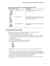
.... Setup displays the maintenance menu again. 9. Jumper Settings for the BIOS Setup Program Modes Jumper Setting Mode Normal (default) (1-2) Description The BIOS uses the current configuration and passwords for booting. Clearing Passwords This procedure assumes that you confirm clearing the password. Observe the precautions in the event of a failed BIOS update. Turn off the computer. Turn off all peripheral devices connected to save the current values and exit Setup. 10. Use the arrow keys to clear passwords. Remove the computer cover. 4. Use this menu to...
.... Setup displays the maintenance menu again. 9. Jumper Settings for the BIOS Setup Program Modes Jumper Setting Mode Normal (default) (1-2) Description The BIOS uses the current configuration and passwords for booting. Clearing Passwords This procedure assumes that you confirm clearing the password. Observe the precautions in the event of a failed BIOS update. Turn off the computer. Turn off all peripheral devices connected to save the current values and exit Setup. 10. Use the arrow keys to clear passwords. Remove the computer cover. 4. Use this menu to...
Product Guide
Page 62
... Firmware Image) • Intel® Integrator Toolkit Configuration File (optional) • Intel Flash Memory Update Utility You can obtain either of these files through your computer supplier or by using either the Iflash Memory Update Utility or the ISO Image BIOS update file. The Iflash BIOS update file is a standardized image of a bootable CD-ROM that can be used to the DP35DP page, click "[view] Latest BIOS updates," and select the ISO Image BIOS Update or Iflash BIOS Update utility file. Intel Desktop Board DP35DP Product Guide Updating...
... Firmware Image) • Intel® Integrator Toolkit Configuration File (optional) • Intel Flash Memory Update Utility You can obtain either of these files through your computer supplier or by using either the Iflash Memory Update Utility or the ISO Image BIOS update file. The Iflash BIOS update file is a standardized image of a bootable CD-ROM that can be used to the DP35DP page, click "[view] Latest BIOS updates," and select the ISO Image BIOS Update or Iflash BIOS Update utility file. Intel Desktop Board DP35DP Product Guide Updating...

Product Guide
Page 64
... USB device. 3. Uncompress the BIOS update file and copy the .BIO file, IFLASH.EXE, and .ITK file (optional) to : http://support.intel.com/support/motherboards/desktop/sb/CS-022312.htm 64 Related Links: For more information about updating the Intel Desktop Board BIOS or recovering from the USB device and manually update the BIOS. Configure the BIOS or use the F10 option during POST to boot to BIOS size and recovery requirements, a CD-R with the .BIO file in the root directory will interrupt the BIOS update; Intel Desktop Board DP35DP Product Guide...
... USB device. 3. Uncompress the BIOS update file and copy the .BIO file, IFLASH.EXE, and .ITK file (optional) to : http://support.intel.com/support/motherboards/desktop/sb/CS-022312.htm 64 Related Links: For more information about updating the Intel Desktop Board BIOS or recovering from the USB device and manually update the BIOS. Configure the BIOS or use the F10 option during POST to boot to BIOS size and recovery requirements, a CD-R with the .BIO file in the root directory will interrupt the BIOS update; Intel Desktop Board DP35DP Product Guide...
Product Guide
Page 66
...CD. 2. Install the Intel® ICH9 SATA RAID Controller driver. If you will be using Microsoft Windows XP, press at http://support.intel.com/support/motherboards/desktop/. Intel Desktop Board DP35DP Product Guide Loading the Intel Matrix Storage Technology RAID Drivers and Software 1. Begin Windows Setup by booting from this section: "Configuring the BIOS for Intel Matrix Storage Technology" and "Loading the Intel Matrix Storage Technology RAID Drivers and Software". Click on the "Load Drivers" option and insert the diskette labeled Intel Matrix Storage Technology RAID Driver (Note...
...CD. 2. Install the Intel® ICH9 SATA RAID Controller driver. If you will be using Microsoft Windows XP, press at http://support.intel.com/support/motherboards/desktop/. Intel Desktop Board DP35DP Product Guide Loading the Intel Matrix Storage Technology RAID Drivers and Software 1. Begin Windows Setup by booting from this section: "Configuring the BIOS for Intel Matrix Storage Technology" and "Loading the Intel Matrix Storage Technology RAID Drivers and Software". Click on the "Load Drivers" option and insert the diskette labeled Intel Matrix Storage Technology RAID Driver (Note...
Product Guide
Page 67
... be Enabled or Disabled in Chapter 5 to RAID and you already have an operating system installed, you want the master drive data to be copied to RAID. Enabling Intel Rapid Recover Technology NOTE Intel Rapid Recover Technology does not support RAID 5. For the setting Configure SATA as was previously not set to the recovery drive continuously or on the master drive while the recovery drive is set to install the Intel Matrix Storage RAID driver during system POST. 2. Enter the BIOS menu...
... be Enabled or Disabled in Chapter 5 to RAID and you already have an operating system installed, you want the master drive data to be copied to RAID. Enabling Intel Rapid Recover Technology NOTE Intel Rapid Recover Technology does not support RAID 5. For the setting Configure SATA as was previously not set to the recovery drive continuously or on the master drive while the recovery drive is set to install the Intel Matrix Storage RAID driver during system POST. 2. Enter the BIOS menu...


