

DH61DL Technical Product Specification
Page 8
... Reliability 60 2.9 Environmental 60 3 Overview of BIOS Features 3.1 Introduction 61 3.2 System Management BIOS (SMBIOS 63 3.3 Legacy USB Support 63 3.4 BIOS Updates 64 3.4.1 Language Support 64 3.4.2 Custom Splash Screen 65 3.5 BIOS Recovery 65 3.6 Boot Options 66 3.6.1 Optical Drive Boot 66 3.6.2 Network Boot 66 3.6.3 Booting Without Attached Devices 66 3.6.4 Changing the Default Boot Device During POST 66 4 Error Messages and Beep Codes 4.1 Speaker 67 4.2 BIOS Beep Codes 67 4.3 Front-panel Power LED Blink Codes 68 4.4 BIOS Error Messages 68 4.5 Port 80h POST Codes 69 viii
... Reliability 60 2.9 Environmental 60 3 Overview of BIOS Features 3.1 Introduction 61 3.2 System Management BIOS (SMBIOS 63 3.3 Legacy USB Support 63 3.4 BIOS Updates 64 3.4.1 Language Support 64 3.4.2 Custom Splash Screen 65 3.5 BIOS Recovery 65 3.6 Boot Options 66 3.6.1 Optical Drive Boot 66 3.6.2 Network Boot 66 3.6.3 Booting Without Attached Devices 66 3.6.4 Changing the Default Boot Device During POST 66 4 Error Messages and Beep Codes 4.1 Speaker 67 4.2 BIOS Beep Codes 67 4.3 Front-panel Power LED Blink Codes 68 4.4 BIOS Error Messages 68 4.5 Port 80h POST Codes 69 viii

DH61DL Technical Product Specification
Page 9
... Diagram 15 3. LAN Connector LED Locations 27 6. Connection Diagram for Intel HD Audio 45 15. Components Shown in Figure 10 44 11. Detailed System Memory Address Map 40 9. Supported Memory Configurations 18 4. Power States and Targeted System Power 32 8. Serial Port Header 45 12. Thermal Sensors and Fan Headers 29 7. Component-side Connectors and Headers 43 11. LAN Connector LED States 27 6. Wake-up Devices and Events 33 9. System Memory Map 41 10. Front Panel Audio Header for Front Panel USB Headers 51 13. Board...
... Diagram 15 3. LAN Connector LED Locations 27 6. Connection Diagram for Intel HD Audio 45 15. Components Shown in Figure 10 44 11. Detailed System Memory Address Map 40 9. Supported Memory Configurations 18 4. Power States and Targeted System Power 32 8. Serial Port Header 45 12. Thermal Sensors and Fan Headers 29 7. Component-side Connectors and Headers 43 11. LAN Connector LED States 27 6. Wake-up Devices and Events 33 9. System Memory Map 41 10. Front Panel Audio Header for Front Panel USB Headers 51 13. Board...

DH61DL Technical Product Specification
Page 10
Chassis Intrusion Header 47 19. Front Panel Header 49 23. BIOS Setup Configuration Jumper Settings 53 27. Fan Header Current Capability 57 30. BIOS Setup Program Menu Bar 62 33. BIOS Setup Program Function Keys 62 34. BIOS Beep Codes 67 37. Port 80h POST Codes 70 41. Typical Port 80h POST Sequence 74 42. SATA Connectors 46 18. States for BIOS Recovery 65 35. Acceptable Drives/Media Types for a One-Color Power LED 50 24. EMC Regulations 79 44. Boot Device Menu Options 66 36. BIOS Error Messages 68...
Chassis Intrusion Header 47 19. Front Panel Header 49 23. BIOS Setup Configuration Jumper Settings 53 27. Fan Header Current Capability 57 30. BIOS Setup Program Menu Bar 62 33. BIOS Setup Program Function Keys 62 34. BIOS Beep Codes 67 37. Port 80h POST Codes 70 41. Typical Port 80h POST Sequence 74 42. SATA Connectors 46 18. States for BIOS Recovery 65 35. Acceptable Drives/Media Types for a One-Color Power LED 50 24. EMC Regulations 79 44. Boot Device Menu Options 66 36. BIOS Error Messages 68...
DH61DL Technical Product Specification
Page 12
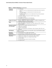
... panel connectors (black) ― Six USB 2.0 front panel ports are implemented through three dual-port internal headers • Three SATA interfaces through the Intel H61 Express Chipset • One serial port header • One parallel port connector on the back panel • One PS/2* keyboard/mouse port on back panel Legacy I/O Control BIOS • Nuvoton* W83677HG-i Super I/O controller for hardware management and serial port, parallel port, and PS/2 support • Intel® BIOS resident in the SPI Flash device • Support for Advanced Configuration and Power Interface (ACPI...
... panel connectors (black) ― Six USB 2.0 front panel ports are implemented through three dual-port internal headers • Three SATA interfaces through the Intel H61 Express Chipset • One serial port header • One parallel port connector on the back panel • One PS/2* keyboard/mouse port on back panel Legacy I/O Control BIOS • Nuvoton* W83677HG-i Super I/O controller for hardware management and serial port, parallel port, and PS/2 support • Intel® BIOS resident in the SPI Flash device • Support for Advanced Configuration and Power Interface (ACPI...
DH61DL Technical Product Specification
Page 16
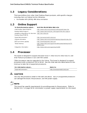
...://processormatch.intel.com CAUTION Use only the processors listed on power supply requirements for providing power to ) the following: • No Parallel ATA (PATA) IDE drive connector 1.3 Online Support To find information about ... NOTE This board has specific requirements for this World Wide Web site: http://www.intel.com/products/motherboard/index.htm http://www.intel.com/p/en_US/support?iid=hdr+support http://ark.intel.com Supported processors Chipset information BIOS and driver updates Tested memory...
...://processormatch.intel.com CAUTION Use only the processors listed on power supply requirements for providing power to ) the following: • No Parallel ATA (PATA) IDE drive connector 1.3 Online Support To find information about ... NOTE This board has specific requirements for this World Wide Web site: http://www.intel.com/products/motherboard/index.htm http://www.intel.com/p/en_US/support?iid=hdr+support http://ark.intel.com Supported processors Chipset information BIOS and driver updates Tested memory...

DH61DL Technical Product Specification
Page 17
... mode support • Supports 1.2 V - 1.8 V DIMM memory voltage • Support for information on page 39 for non-ECC, unbuffered, single-sided or double-sided DIMMs with x8 organization • 16 GB maximum total system memory (with DIMMs that support the Serial Presence Detect (SPD) data structure. For information about The Intel H61 Express chipset Resources used by the chipset Refer to the processor and the USB, SATA, LPC, audio, network, display...
... mode support • Supports 1.2 V - 1.8 V DIMM memory voltage • Support for information on page 39 for non-ECC, unbuffered, single-sided or double-sided DIMMs with x8 organization • 16 GB maximum total system memory (with DIMMs that support the Serial Presence Detect (SPD) data structure. For information about The Intel H61 Express chipset Resources used by the chipset Refer to the processor and the USB, SATA, LPC, audio, network, display...
DH61DL Technical Product Specification
Page 26
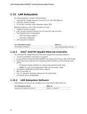
...) mode] • Dual interconnect between the PCH and the LAN controller • PCI Express power management ACPI technology support LAN wake capabilities • LAN subsystem software For information about Obtaining LAN software and drivers Refer to IEEE 802.3x flow control support • 802.1p and 802.1q • TCP, IP, and UDP checksum offload (for IPv4 and IPv6) • Full device driver compatibility 1.12.2 LAN Subsystem Software LAN software and drivers are available from Intel...
...) mode] • Dual interconnect between the PCH and the LAN controller • PCI Express power management ACPI technology support LAN wake capabilities • LAN subsystem software For information about Obtaining LAN software and drivers Refer to IEEE 802.3x flow control support • 802.1p and 802.1q • TCP, IP, and UDP checksum offload (for IPv4 and IPv6) • Full device driver compatibility 1.12.2 LAN Subsystem Software LAN software and drivers are available from Intel...

DH61DL Technical Product Specification
Page 31
... PC technology Wake from USB PCI Express WAKE# signal support Wake from serial port Wake from PS/2 1.16.1 ACPI ACPI gives the operating system direct control over the power management and Plug and Play functions of Pressing the Power Switch If the system is in this ...and the power switch is state... The use of individual devices, add-in boards (some add-in boards may require an ACPI-aware driver), video displays, and hard disk drives •...
... PC technology Wake from USB PCI Express WAKE# signal support Wake from serial port Wake from PS/2 1.16.1 ACPI ACPI gives the operating system direct control over the power management and Plug and Play functions of Pressing the Power Switch If the system is in this ...and the power switch is state... The use of individual devices, add-in boards (some add-in boards may require an ACPI-aware driver), video displays, and hard disk drives •...

DH61DL Technical Product Specification
Page 51
... POST code generated is a connection diagram for high-speed USB devices. The POST card can interface with the Low Pin Count (LPC) Debug header. Connection Diagram for a description of the POST codes). Displaying the POST codes requires a POST card that conforms to I/O port 80h. Technical Reference 2.2.2.6 Front Panel USB Headers Figure 12 is left at port 80h. This code is fused. • Use only a front panel USB connector that can decode the port and display the contents on page 69 for Front Panel USB Headers 2.2.2.7 Low Pin...
... POST code generated is a connection diagram for high-speed USB devices. The POST card can interface with the Low Pin Count (LPC) Debug header. Connection Diagram for a description of the POST codes). Displaying the POST codes requires a POST card that conforms to I/O port 80h. Technical Reference 2.2.2.6 Front Panel USB Headers Figure 12 is left at port 80h. This code is fused. • Use only a front panel USB connector that can decode the port and display the contents on page 69 for Front Panel USB Headers 2.2.2.7 Low Pin...

DH61DL Technical Product Specification
Page 61
... The BIOS displays a message during POST identifying the type of utilities. Maintenance Main Configuration Performance Security Power Boot Exit NOTE The maintenance menu is displayed only when the board is accessed by pressing the key after the Power-On Self-Test (POST) memory test begins and before the operating system boot begins. The menu bar is shown below. The SPI Flash contains the BIOS Setup program, POST, LAN EEPROM information, Plug and Play support, and other firmware.
... The BIOS displays a message during POST identifying the type of utilities. Maintenance Main Configuration Performance Security Power Boot Exit NOTE The maintenance menu is displayed only when the board is accessed by pressing the key after the Power-On Self-Test (POST) memory test begins and before the operating system boot begins. The menu bar is shown below. The SPI Flash contains the BIOS Setup program, POST, LAN EEPROM information, Plug and Play support, and other firmware.

DH61DL Technical Product Specification
Page 62
... Memory, Bus and Processor overrides Sets passwords and security features Power Configures power management features and power supply controls Boot Selects boot options Exit Saves or discards changes to Setup program options Table 33 lists the function keys available for the current menu Save the current values and exits the BIOS Setup program Exits the menu 62 BIOS Setup Program Menu Bar Maintenance Main Configura- Intel Desktop Board DH61DL Technical Product Specification Table 32 lists the BIOS Setup program menu features. BIOS Setup Program Function Keys BIOS Setup...
... Memory, Bus and Processor overrides Sets passwords and security features Power Configures power management features and power supply controls Boot Selects boot options Exit Saves or discards changes to Setup program options Table 33 lists the function keys available for the current menu Save the current values and exits the BIOS Setup program Exits the menu 62 BIOS Setup Program Menu Bar Maintenance Main Configura- Intel Desktop Board DH61DL Technical Product Specification Table 32 lists the BIOS Setup program menu features. BIOS Setup Program Function Keys BIOS Setup...

DH61DL Technical Product Specification
Page 63
... such as third-party management software to use a USB keyboard to the computer, legacy support is disabled. 2. The operating system loads. By default, Legacy USB support is set to Enabled. POST begins. 3. After the operating system loads the USB drivers, all legacy and non-legacy USB devices are recognized by the BIOS allowing you apply power to enter and configure the BIOS Setup program and the maintenance menu. 4. Overview of SMBIOS is the Management Information Format (MIF) database, which...
... such as third-party management software to use a USB keyboard to the computer, legacy support is disabled. 2. The operating system loads. By default, Legacy USB support is set to Enabled. POST begins. 3. After the operating system loads the USB drivers, all legacy and non-legacy USB devices are recognized by the BIOS allowing you apply power to enter and configure the BIOS Setup program and the maintenance menu. 4. Overview of SMBIOS is the Management Information Format (MIF) database, which...

DH61DL Technical Product Specification
Page 68
.... Replace the battery soon. System did not find a device to reset values. Note For processors requiring an add-in graphics card installed) On-off (1.0 second each . Run Setup to boot. 68 BIOS Error Messages Error Message Explanation CMOS Battery Low CMOS Checksum Bad The battery may have been corrupted. Table 38. Table 37. Video error (no memory was removed, then memory may be losing power. Intel Desktop Board DH61DL Technical Product Specification 4.3 Front-panel Power LED Blink Codes Whenever a recoverable error occurs during POST...
.... Replace the battery soon. System did not find a device to reset values. Note For processors requiring an add-in graphics card installed) On-off (1.0 second each . Run Setup to boot. 68 BIOS Error Messages Error Message Explanation CMOS Battery Low CMOS Checksum Bad The battery may have been corrupted. Table 38. Table 37. Video error (no memory was removed, then memory may be losing power. Intel Desktop Board DH61DL Technical Product Specification 4.3 Front-panel Power LED Blink Codes Whenever a recoverable error occurs during POST...
DH61DL Technical Product Specification
Page 69
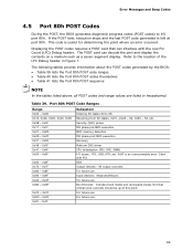
... Entering SX states S0 to the location of the LPC Debug header in hexadecimal. Error Messages and Beep Codes 4.5 Port 80h POST Codes During the POST, the BIOS generates diagnostic progress codes (POST codes) to I /O buses: PCI, USB, ATA, etc. 0x5F is left at this point. The POST card can interface with PCI. Start with the Low Pin Count (LPC) Debug header. For future use Boot Devices: Includes fixed media and removable media. Displaying the POST codes requires a POST card that...
... Entering SX states S0 to the location of the LPC Debug header in hexadecimal. Error Messages and Beep Codes 4.5 Port 80h POST Codes During the POST, the BIOS generates diagnostic progress codes (POST codes) to I /O buses: PCI, USB, ATA, etc. 0x5F is left at this point. The POST card can interface with PCI. Start with the Low Pin Count (LPC) Debug header. For future use Boot Devices: Includes fixed media and removable media. Displaying the POST codes requires a POST card that...
English Product Guide
Page 3
... damage to important information. NOTE Notes call attention to hardware or loss of data. Document Organization The chapters in this Product Guide are arranged as follows: 1 Desktop Board Features: a summary of this manual: CAUTION Cautions warn the user about board layout, component installation, BIOS update, and regulatory requirements for Intel® Desktop Board DH61DL. It is intended for general audiences. Intended Audience The Product...
... damage to important information. NOTE Notes call attention to hardware or loss of data. Document Organization The chapters in this Product Guide are arranged as follows: 1 Desktop Board Features: a summary of this manual: CAUTION Cautions warn the user about board layout, component installation, BIOS update, and regulatory requirements for Intel® Desktop Board DH61DL. It is intended for general audiences. Intended Audience The Product...

English Product Guide
Page 5
...15 Main Memory...15 Graphics Subsystem 16 Integrated Graphics 16 Analog Display 16 Digital Visual Interface 16 PCI Express* x1 Graphics 16 Audio Subsystem 17 LAN Subsystem 18 USB Support ...19 SATA Support...19 Expandability...19 Legacy I/O ...19 BIOS ...20 SATA Auto Configuration 20 PCI Express Auto Configuration 20 BIOS Security Passwords 20 Intel Manageability Technology 21 Intel® MEBX Reset Header 21 Fan Speed Control and Hardware Monitoring 22 Power Management 22 Software Support 22 Hardware Support 23 Onboard Speaker 26 Real-Time Clock Subsystem 26 2 Installing and...
...15 Main Memory...15 Graphics Subsystem 16 Integrated Graphics 16 Analog Display 16 Digital Visual Interface 16 PCI Express* x1 Graphics 16 Audio Subsystem 17 LAN Subsystem 18 USB Support ...19 SATA Support...19 Expandability...19 Legacy I/O ...19 BIOS ...20 SATA Auto Configuration 20 PCI Express Auto Configuration 20 BIOS Security Passwords 20 Intel Manageability Technology 21 Intel® MEBX Reset Header 21 Fan Speed Control and Hardware Monitoring 22 Power Management 22 Software Support 22 Hardware Support 23 Onboard Speaker 26 Real-Time Clock Subsystem 26 2 Installing and...

English Product Guide
Page 6
... Audio Header 43 Internal Mono Speaker Header 43 Front Panel USB 2.0 Headers 44 Front Panel Header 44 Alternate Front Panel Power LED Header 45 Serial Header 45 Chassis Intrusion Header 45 S/PDIF Header 46 Connecting to the Audio System 46 Connecting System Fan and Power Supply Cables 47 Connecting a System Fan Cable 47 Connecting Power Supply Cables 48 Setting the BIOS Configuration Jumper 49 Clearing Passwords in the BIOS Setup Program 50 Replacing the Battery 51 3 Updating the BIOS Updating the BIOS with the Intel® Express BIOS Update Utility 57 Updating the BIOS Using...
... Audio Header 43 Internal Mono Speaker Header 43 Front Panel USB 2.0 Headers 44 Front Panel Header 44 Alternate Front Panel Power LED Header 45 Serial Header 45 Chassis Intrusion Header 45 S/PDIF Header 46 Connecting to the Audio System 46 Connecting System Fan and Power Supply Cables 47 Connecting a System Fan Cable 47 Connecting Power Supply Cables 48 Setting the BIOS Configuration Jumper 49 Clearing Passwords in the BIOS Setup Program 50 Replacing the Battery 51 3 Updating the BIOS Updating the BIOS with the Intel® Express BIOS Update Utility 57 Updating the BIOS Using...
English Product Guide
Page 20
... the BIOS Setup program after installing a SATA device. If only the supervisor password is booted. If both the supervisor and user passwords are set , you install a PCI Express add-in the Serial Peripheral Interface (SPI) Flash memory device. You do not need to boot the computer. For instructions on page 57. You can boot the computer. PCI Express Auto Configuration If you install a SATA device (such as a hard disk drive) in your computer, the autoconfiguration utility in Chapter 3 starting on resetting the password, go...
... the BIOS Setup program after installing a SATA device. If only the supervisor password is booted. If both the supervisor and user passwords are set , you install a PCI Express add-in the Serial Peripheral Interface (SPI) Flash memory device. You do not need to boot the computer. For instructions on page 57. You can boot the computer. PCI Express Auto Configuration If you install a SATA device (such as a hard disk drive) in your computer, the autoconfiguration utility in Chapter 3 starting on resetting the password, go...

English Product Guide
Page 50
.... 2. Turn off the computer. Turn off all peripheral devices connected to be done in the computer, turn on pins 2-3 as shown below. 6. Configure (2-3) After the Power-On Self-Test (POST) runs, the BIOS displays the Maintenance Menu. Remove the computer cover. 4. Place the jumper on the computer, and allow it to normal mode. 1. Setup displays the Maintenance menu. 50 Intel Desktop Board DH61DL Product Guide The three-pin BIOS jumper block enables board configuration to the computer. Use this menu to clear passwords.
.... 2. Turn off the computer. Turn off all peripheral devices connected to be done in the computer, turn on pins 2-3 as shown below. 6. Configure (2-3) After the Power-On Self-Test (POST) runs, the BIOS displays the Maintenance Menu. Remove the computer cover. 4. Place the jumper on the computer, and allow it to normal mode. 1. Setup displays the Maintenance menu. 50 Intel Desktop Board DH61DL Product Guide The three-pin BIOS jumper block enables board configuration to the computer. Use this menu to clear passwords.

English Product Guide
Page 57
... can access the BIOS Setup program by either using the Intel Express BIOS Update utility or the Intel® Flash Memory Update Utility, and how to a removable USB device. Click on your hard drive. (You can also save this file to recover the BIOS if an update fails. The BIOS file is included in the dialog boxes to update the BIOS by pressing the key after the Power-On Self-Test (POST) memory test begins and before the operating system boot...
... can access the BIOS Setup program by either using the Intel Express BIOS Update utility or the Intel® Flash Memory Update Utility, and how to a removable USB device. Click on your hard drive. (You can also save this file to recover the BIOS if an update fails. The BIOS file is included in the dialog boxes to update the BIOS by pressing the key after the Power-On Self-Test (POST) memory test begins and before the operating system boot...


