
Technical Product Specification
Page 8
... Reliability 60 2.9 Environmental 60 3 Overview of BIOS Features 3.1 Introduction 61 3.2 System Management BIOS (SMBIOS 63 3.3 Legacy USB Support 63 3.4 BIOS Updates 64 3.4.1 Language Support 64 3.4.2 Custom Splash Screen 65 3.5 BIOS Recovery 65 3.6 Boot Options 66 3.6.1 Optical Drive Boot 66 3.6.2 Network Boot 66 3.6.3 Booting Without Attached Devices 66 3.6.4 Changing the Default Boot Device During POST 66 4 Error Messages and Beep Codes 4.1 Speaker 67 4.2 BIOS Beep Codes 67 4.3 Front-panel Power LED Blink Codes 68 4.4 BIOS Error Messages 68 4.5 Port 80h POST Codes 69 viii
... Reliability 60 2.9 Environmental 60 3 Overview of BIOS Features 3.1 Introduction 61 3.2 System Management BIOS (SMBIOS 63 3.3 Legacy USB Support 63 3.4 BIOS Updates 64 3.4.1 Language Support 64 3.4.2 Custom Splash Screen 65 3.5 BIOS Recovery 65 3.6 Boot Options 66 3.6.1 Optical Drive Boot 66 3.6.2 Network Boot 66 3.6.3 Booting Without Attached Devices 66 3.6.4 Changing the Default Boot Device During POST 66 4 Error Messages and Beep Codes 4.1 Speaker 67 4.2 BIOS Beep Codes 67 4.3 Front-panel Power LED Blink Codes 68 4.4 BIOS Error Messages 68 4.5 Port 80h POST Codes 69 viii
Technical Product Specification
Page 9
... 1 14 3. TPM Header 45 12. Feature Summary 11 2. System Memory Map 41 10. Memory Channel and DIMM Configuration 19 4. LAN Connector LED Locations 27 6. Thermal Sensors and Fan Headers 29 7. Connection Diagram for Front Panel USB Headers 51 13. Intel MEBX Reset Header 54 15. Audio Jack Support 23 5. Serial Port Header 45 13. Supported Memory Configurations 18 4. Internal Mono Speaker Header 45 15. Localized High Temperature Zones 59 Tables 1. Front Panel Audio Header for Intel HD Audio 46 ix Block Diagram 15 3. Power States and Targeted...
... 1 14 3. TPM Header 45 12. Feature Summary 11 2. System Memory Map 41 10. Memory Channel and DIMM Configuration 19 4. LAN Connector LED Locations 27 6. Thermal Sensors and Fan Headers 29 7. Connection Diagram for Front Panel USB Headers 51 13. Intel MEBX Reset Header 54 15. Audio Jack Support 23 5. Serial Port Header 45 13. Supported Memory Configurations 18 4. Internal Mono Speaker Header 45 15. Localized High Temperature Zones 59 Tables 1. Front Panel Audio Header for Intel HD Audio 46 ix Block Diagram 15 3. Power States and Targeted...
Technical Product Specification
Page 10
.... Intel MEBX Reset Header Signals 54 29. Front-panel Power LED Blink Codes 68 39. Port 80h POST Codes 70 42. SATA Connectors 46 19. BIOS Beep Codes 67 38. Typical Port 80h POST Sequence 74 43. Fan Headers 47 21. BIOS Setup Configuration Jumper Settings 53 28. Regulatory Compliance Marks 83 x Acceptable Drives/Media Types for AC '97 Audio 46 17. Safety Standards 75 44. Main Power Connector 48 23. Environmental Specifications 60 33. Intel Desktop Board DH61BE Technical Product Specification 16. Front Panel Audio Header for BIOS Recovery 65...
.... Intel MEBX Reset Header Signals 54 29. Front-panel Power LED Blink Codes 68 39. Port 80h POST Codes 70 42. SATA Connectors 46 19. BIOS Beep Codes 67 38. Typical Port 80h POST Sequence 74 43. Fan Headers 47 21. BIOS Setup Configuration Jumper Settings 53 28. Regulatory Compliance Marks 83 x Acceptable Drives/Media Types for AC '97 Audio 46 17. Safety Standards 75 44. Main Power Connector 48 23. Environmental Specifications 60 33. Intel Desktop Board DH61BE Technical Product Specification 16. Front Panel Audio Header for BIOS Recovery 65...
Technical Product Specification
Page 16
... the board, the processor, and the power supply. Use of 95 W. For information about ... This board is designed to support the Intel Core i7, Intel Core i5, Intel Core i3, and Intel Pentium processors in the future. Supported processors Refer to the processor. Intel Desktop Board DH61BE Desktop Board Support Available configurations for this World Wide Web site: http://www.intel.com/products/motherboard/index.htm http://www.intel.com/p/en_US/support?iid=hdr+support http://ark.intel.com Supported processors Chipset information BIOS and driver updates Tested memory...
... the board, the processor, and the power supply. Use of 95 W. For information about ... This board is designed to support the Intel Core i7, Intel Core i5, Intel Core i3, and Intel Pentium processors in the future. Supported processors Refer to the processor. Intel Desktop Board DH61BE Desktop Board Support Available configurations for this World Wide Web site: http://www.intel.com/products/motherboard/index.htm http://www.intel.com/p/en_US/support?iid=hdr+support http://ark.intel.com Supported processors Chipset information BIOS and driver updates Tested memory...
Technical Product Specification
Page 17
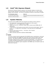
... Express chipset Resources used by the chipset Refer to the processor and the USB, SATA, LPC, audio, network, display, and PCI Express. Refer to Section 2.1.1 on the total amount of the Intel H61 Platform Controller Hub (PCH) provides interfaces to http://www.intel.com/products/desktop/chipsets/index.htm Chapter 2 1.6 System Memory The board has two DIMM sockets and supports the following memory features: • Two independent memory channels with interleaved mode support • Supports 1.2 V - 1.8 V DIMM memory voltage • Support...
... Express chipset Resources used by the chipset Refer to the processor and the USB, SATA, LPC, audio, network, display, and PCI Express. Refer to Section 2.1.1 on the total amount of the Intel H61 Platform Controller Hub (PCH) provides interfaces to http://www.intel.com/products/desktop/chipsets/index.htm Chapter 2 1.6 System Memory The board has two DIMM sockets and supports the following memory features: • Two independent memory channels with interleaved mode support • Supports 1.2 V - 1.8 V DIMM memory voltage • Support...
Technical Product Specification
Page 21
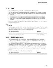
... location of the front panel USB headers Refer to ten USB 2.0 ports and two USB 3.0 ports. The Intel H61 Express Chipset provides the USB controller for configurations using the Windows* XP, Windows Vista*, and Windows 7* operating systems. For more information, see: http://www.serialata.org/. NOTE Computer systems that meets the requirements for full-speed devices. In legacy mode, standard IDE I/O and IRQ resources are high-speed, full-speed, and low-speed capable. Native mode is used. The two USB 3.0 ports...
... location of the front panel USB headers Refer to ten USB 2.0 ports and two USB 3.0 ports. The Intel H61 Express Chipset provides the USB controller for configurations using the Windows* XP, Windows Vista*, and Windows 7* operating systems. For more information, see: http://www.serialata.org/. NOTE Computer systems that meets the requirements for full-speed devices. In legacy mode, standard IDE I/O and IRQ resources are high-speed, full-speed, and low-speed capable. Native mode is used. The two USB 3.0 ports...
Technical Product Specification
Page 26
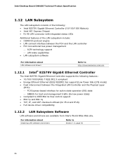
... 26 Intel Desktop Board DH61BE Technical Product Specification 1.12 LAN Subsystem The LAN subsystem consists of the following features: • 10/100/1000 BASE-T IEEE 802.3 compliant • Energy Efficient Ethernet (EEE) IEEE802.3az support [Low Power Idle (LPI) mode] • Dual interconnect between the PCH and the LAN controller • PCI Conventional bus power management ACPI technology support LAN wake capabilities • LAN subsystem software For information about Obtaining LAN software and drivers...
... 26 Intel Desktop Board DH61BE Technical Product Specification 1.12 LAN Subsystem The LAN subsystem consists of the following features: • 10/100/1000 BASE-T IEEE 802.3 compliant • Energy Efficient Ethernet (EEE) IEEE802.3az support [Low Power Idle (LPI) mode] • Dual interconnect between the PCH and the LAN controller • PCI Conventional bus power management ACPI technology support LAN wake capabilities • LAN subsystem software For information about Obtaining LAN software and drivers...
Technical Product Specification
Page 31
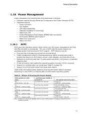
... (ACPI G2/G5 - ACPI features include: • Plug and Play (including bus and device enumeration) • Power management control of ACPI with an ACPI-aware operating system. working state) Sleep (ACPI G1 - Product Description 1.16 Power Management Power management is implemented at several levels, including: • Software support through Advanced Configuration and Power Interface (ACPI) • Hardware support: Power connector Fan headers LAN wake capabilities Instantly Available PC technology Wake from PS/2 1.16.1 ACPI ACPI...
... (ACPI G2/G5 - ACPI features include: • Plug and Play (including bus and device enumeration) • Power management control of ACPI with an ACPI-aware operating system. working state) Sleep (ACPI G1 - Product Description 1.16 Power Management Power management is implemented at several levels, including: • Software support through Advanced Configuration and Power Interface (ACPI) • Hardware support: Power connector Fan headers LAN wake capabilities Instantly Available PC technology Wake from PS/2 1.16.1 ACPI ACPI...
Technical Product Specification
Page 51
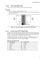
NOTE • The +5 V DC power on the USB headers is fused. • Use only a front panel USB connector that can decode the port and display the contents on page 69 for high-speed USB devices. If the POST fails, execution stops and the last POST code generated is useful for the front panel USB headers. LPC Debug Header Pin Signal Name 1 CK_33M_DEBUG 3 PLTRST# 5 LAD0 7 LAD2 9 GND 11 +3.3 V 13 Not connected Pin Signal Name 2 GND 4 LFRAME...
NOTE • The +5 V DC power on the USB headers is fused. • Use only a front panel USB connector that can decode the port and display the contents on page 69 for high-speed USB devices. If the POST fails, execution stops and the last POST code generated is useful for the front panel USB headers. LPC Debug Header Pin Signal Name 1 CK_33M_DEBUG 3 PLTRST# 5 LAD0 7 LAD2 9 GND 11 +3.3 V 13 Not connected Pin Signal Name 2 GND 4 LFRAME...
Technical Product Specification
Page 62
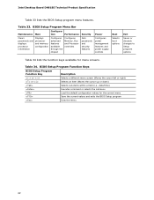
...Security Clears passwords and displays processor information Displays processor and memory configuration Configures advanced features available through the chipset Configures Memory, Bus and Processor overrides Sets passwords and security features Power Configures power management features and power supply controls Boot Selects boot options Exit Saves or discards changes to Setup program options Table 34 lists the function keys available for the current menu Save the current values and exits the BIOS Setup program Exits the menu 62 BIOS Setup Program Menu Bar Maintenance Main...
...Security Clears passwords and displays processor information Displays processor and memory configuration Configures advanced features available through the chipset Configures Memory, Bus and Processor overrides Sets passwords and security features Power Configures power management features and power supply controls Boot Selects boot options Exit Saves or discards changes to Setup program options Table 34 lists the function keys available for the current menu Save the current values and exits the BIOS Setup program Exits the menu 62 BIOS Setup Program Menu Bar Maintenance Main...
Technical Product Specification
Page 68
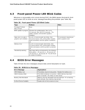
... each . Memory error On-off . Front-panel Power LED Blink Codes Type Pattern F2 Setup/F10 Boot Menu Prompt None BIOS update in a total of each ) three times, then 2.5-second pause (off), entire pattern repeats (blinks and pause) until the BIOS update is powered off . Intel Desktop Board DH61BE Technical Product Specification 4.3 Front-panel Power LED Blink Codes Whenever a recoverable error occurs during POST, the BIOS causes the board's front panel power LED to blink an error message describing the problem (see Table...
... each . Memory error On-off . Front-panel Power LED Blink Codes Type Pattern F2 Setup/F10 Boot Menu Prompt None BIOS update in a total of each ) three times, then 2.5-second pause (off), entire pattern repeats (blinks and pause) until the BIOS update is powered off . Intel Desktop Board DH61BE Technical Product Specification 4.3 Front-panel Power LED Blink Codes Whenever a recoverable error occurs during POST, the BIOS causes the board's front panel power LED to blink an error message describing the problem (see Table...
Technical Product Specification
Page 69
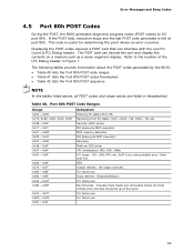
Refer to the location of the LPC Debug header in hexadecimal. Start with the Low Pin Count (LPC) Debug header. For future use For future use Boot Devices: Includes fixed media and removable media. Error Messages and Beep Codes 4.5 Port 80h POST Codes During the POST, the BIOS generates diagnostic progress codes (POST codes) to I /O buses: PCI, USB, ATA, etc. 0x5F is an unrecoverable error. Table 40. For future use 69 This code is left at this...
Refer to the location of the LPC Debug header in hexadecimal. Start with the Low Pin Count (LPC) Debug header. For future use For future use Boot Devices: Includes fixed media and removable media. Error Messages and Beep Codes 4.5 Port 80h POST Codes During the POST, the BIOS generates diagnostic progress codes (POST codes) to I /O buses: PCI, USB, ATA, etc. 0x5F is an unrecoverable error. Table 40. For future use 69 This code is left at this...
English Product Guide
Page 3
... and EMC regulations and its product certifications Conventions The following conventions are used in this product for other PC or embedded non-PC applications or other hardware components 3 Updating the BIOS: instructions on how to update the BIOS A Error Messages and Indicators: information about board layout, component installation, BIOS update, and regulatory requirements for Intel® Desktop Board DH61BE. may not be supported without further evaluation by...
... and EMC regulations and its product certifications Conventions The following conventions are used in this product for other PC or embedded non-PC applications or other hardware components 3 Updating the BIOS: instructions on how to update the BIOS A Error Messages and Indicators: information about board layout, component installation, BIOS update, and regulatory requirements for Intel® Desktop Board DH61BE. may not be supported without further evaluation by...
English Product Guide
Page 5
... (VGA 16 Digital Visual Interface 16 PCI Express* x16 Graphics 16 Audio Subsystem 17 LAN Subsystem 18 USB Support ...19 SATA Support...19 Expandability...20 Legacy I/O ...20 BIOS ...20 SATA Auto Configuration 20 PCI*/PCI Express Auto Configuration 20 BIOS Security Passwords 21 Intel Manageability Technology 21 Intel® MEBX Reset Header 21 Trusted Platform Module (TPM) Support 22 Fan Speed Control and Hardware Monitoring 23 Power Management 23 Software Support 23 Hardware Support 23 Onboard Speaker 26 Real-Time Clock Subsystem 27 2 Installing and Replacing Desktop Board...
... (VGA 16 Digital Visual Interface 16 PCI Express* x16 Graphics 16 Audio Subsystem 17 LAN Subsystem 18 USB Support ...19 SATA Support...19 Expandability...20 Legacy I/O ...20 BIOS ...20 SATA Auto Configuration 20 PCI*/PCI Express Auto Configuration 20 BIOS Security Passwords 21 Intel Manageability Technology 21 Intel® MEBX Reset Header 21 Trusted Platform Module (TPM) Support 22 Fan Speed Control and Hardware Monitoring 23 Power Management 23 Software Support 23 Hardware Support 23 Onboard Speaker 26 Real-Time Clock Subsystem 27 2 Installing and Replacing Desktop Board...
English Product Guide
Page 6
...PDIF Header 46 Front Panel USB 2.0 Headers 47 Chassis Intrusion Header 47 TPM Header 48 Front Panel Header 48 Alternate Front Panel Power LED Header 49 Serial Header 49 Internal Mono Speaker Header 49 Connecting to the Audio System 50 Connecting Chassis Fan and Power Supply Cables 51 Connecting Chassis Fan Cables 51 Connecting Power Supply Cables 52 Setting the BIOS Configuration Jumper 53 Clearing Passwords in the BIOS Setup Program 54 Replacing the Battery 55 3 Updating the BIOS Updating the BIOS with the Intel® Express BIOS Update Utility 61 Updating the BIOS Using the...
...PDIF Header 46 Front Panel USB 2.0 Headers 47 Chassis Intrusion Header 47 TPM Header 48 Front Panel Header 48 Alternate Front Panel Power LED Header 49 Serial Header 49 Internal Mono Speaker Header 49 Connecting to the Audio System 50 Connecting Chassis Fan and Power Supply Cables 51 Connecting Chassis Fan Cables 51 Connecting Power Supply Cables 52 Setting the BIOS Configuration Jumper 53 Clearing Passwords in the BIOS Setup Program 54 Replacing the Battery 55 3 Updating the BIOS Updating the BIOS with the Intel® Express BIOS Update Utility 61 Updating the BIOS Using the...
English Product Guide
Page 20
... BIOS Setup program after installing a SATA device. SATA Auto Configuration If you install a Conventional PCI or PCI Express add-in the Serial Peripheral Interface (SPI) Flash memory device. You do not need to run the BIOS Setup program after you install a SATA device (such as a hard disk drive) in your computer. You can be updated by specifying manual configuration in Chapter 3 starting on the back panel • Serial IRQ interface compatible with serialized IRQ support for Conventional PCI bus systems • Intelligent power management, including a programmable wake...
... BIOS Setup program after installing a SATA device. SATA Auto Configuration If you install a Conventional PCI or PCI Express add-in the Serial Peripheral Interface (SPI) Flash memory device. You do not need to run the BIOS Setup program after you install a SATA device (such as a hard disk drive) in your computer. You can be updated by specifying manual configuration in Chapter 3 starting on the back panel • Serial IRQ interface compatible with serialized IRQ support for Conventional PCI bus systems • Intelligent power management, including a programmable wake...

English Product Guide
Page 24
... location of the power connectors. Failure to its last known wake state. When signaled by the BIOS "S3 State Indicator" option). See Figure 22 on or off (the power supply is wired to a tachometer input. • All fan headers support closed-loop fan control that can damage the power supply and/or effect ACPI S3 sleep state functionality. The Desktop Board supports the PCI Bus Power Management Interface Specification. Add-in cards that support this specification can participate in power...
... location of the power connectors. Failure to its last known wake state. When signaled by the BIOS "S3 State Indicator" option). See Figure 22 on or off (the power supply is wired to a tachometer input. • All fan headers support closed-loop fan control that can damage the power supply and/or effect ACPI S3 sleep state functionality. The Desktop Board supports the PCI Bus Power Management Interface Specification. Add-in cards that support this specification can participate in power...
English Product Guide
Page 29
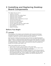
...; Install and remove memory • Install and remove a PCI Express x16 card • Connect Serial ATA cables • Connect to the internal headers • Connect to the audio system • Connect chassis fan and power supply cables • Set the BIOS configuration jumper • Clear passwords • Replace the battery Before You Begin CAUTIONS The procedures in this chapter only at an ESD workstation using and modifying electronic equipment. Some circuitry on the board can continue to operate even though the front panel power button...
...; Install and remove memory • Install and remove a PCI Express x16 card • Connect Serial ATA cables • Connect to the internal headers • Connect to the audio system • Connect chassis fan and power supply cables • Set the BIOS configuration jumper • Clear passwords • Replace the battery Before You Begin CAUTIONS The procedures in this chapter only at an ESD workstation using and modifying electronic equipment. Some circuitry on the board can continue to operate even though the front panel power button...
English Product Guide
Page 54
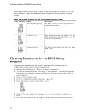
...mode. 1. Intel Desktop Board DH61BE Product Guide The three-pin BIOS jumper block enables board configuration to be done in the computer and the configuration jumper block is installed in the BIOS Setup program. Jumper Settings for the BIOS Setup Program Modes Jumper Setting Mode Normal (default) (1-2) Description The BIOS uses the current configuration and passwords for the BIOS Setup program modes. Replace the cover, plug in the computer, turn on pins 2-3 as shown below. 6. Turn off all peripheral devices connected to the computer. Use this menu to boot. 7. Recovery...
...mode. 1. Intel Desktop Board DH61BE Product Guide The three-pin BIOS jumper block enables board configuration to be done in the computer and the configuration jumper block is installed in the BIOS Setup program. Jumper Settings for the BIOS Setup Program Modes Jumper Setting Mode Normal (default) (1-2) Description The BIOS uses the current configuration and passwords for the BIOS Setup program modes. Replace the cover, plug in the computer, turn on pins 2-3 as shown below. 6. Turn off all peripheral devices connected to the computer. Use this menu to boot. 7. Recovery...
English Product Guide
Page 61
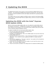
... file to a removable USB device. Double-click the executable file from the location on the "BIOS Update" link and then select the Express BIOS Update file. 3. You can also save this file to your hard drive where it was saved. Navigate to recover the BIOS if an update fails. Follow the instructions provided in an automated update utility that combines the functionality of the Intel Flash Memory Update Utility and the ease of use of Windows-based installation...
... file to a removable USB device. Double-click the executable file from the location on the "BIOS Update" link and then select the Express BIOS Update file. 3. You can also save this file to your hard drive where it was saved. Navigate to recover the BIOS if an update fails. Follow the instructions provided in an automated update utility that combines the functionality of the Intel Flash Memory Update Utility and the ease of use of Windows-based installation...


