
Technical Product Specification
Page 7
... Typographical Conventions v 1 Product Description 1.1 Overview 11 1.1.1 Feature Summary 11 1.1.2 Board Layout 13 1.1.3 Block Diagram 15 1.2 Legacy Considerations 16 1.3 Online Support 16 1.4 Processor 16 1.5 Intel® H61 Express Chipset 17 1.6 System Memory 17 1.6.1 Memory Configurations 18 1.7 Graphics Subsystem 20 1.7.1 Integrated ...Subsystem 23 1.11.1 Audio Subsystem Software 24 1.11.2 Audio Headers and Connectors 24 1.12 LAN Subsystem 26 1.12.1 Intel® 82579V Gigabit Ethernet Controller 26 1.12.2 LAN Subsystem Software 26 1.12.3 RJ-45 LAN Connector with Integrated ...
... Typographical Conventions v 1 Product Description 1.1 Overview 11 1.1.1 Feature Summary 11 1.1.2 Board Layout 13 1.1.3 Block Diagram 15 1.2 Legacy Considerations 16 1.3 Online Support 16 1.4 Processor 16 1.5 Intel® H61 Express Chipset 17 1.6 System Memory 17 1.6.1 Memory Configurations 18 1.7 Graphics Subsystem 20 1.7.1 Integrated ...Subsystem 23 1.11.1 Audio Subsystem Software 24 1.11.2 Audio Headers and Connectors 24 1.12 LAN Subsystem 26 1.12.1 Intel® 82579V Gigabit Ethernet Controller 26 1.12.2 LAN Subsystem Software 26 1.12.3 RJ-45 LAN Connector with Integrated ...
Technical Product Specification
Page 9
... Zones 59 Tables 1. Audio Jack Support 23 5. Wake-up Devices and Events 33 9. TPM Header 45 12. Connection Diagram for Front Panel Header 49 12. Intel MEBX Reset Header 54 15. Components Shown in Figure 10 44 11. Power States and Targeted System Power 32 8. Internal...75 5.1.1 Safety Standards 75 5.1.2 European Union Declaration of the Jumper Block 52 14. Block Diagram 15 3. Back Panel Connectors 42 10. LAN Connector LED States 27 6. Front Panel Audio Header for Intel HD Audio 46 ix Location of Pressing the Power Switch 31 7. Board Dimensions 55 16...
... Zones 59 Tables 1. Audio Jack Support 23 5. Wake-up Devices and Events 33 9. TPM Header 45 12. Connection Diagram for Front Panel Header 49 12. Intel MEBX Reset Header 54 15. Components Shown in Figure 10 44 11. Power States and Targeted System Power 32 8. Internal...75 5.1.1 Safety Standards 75 5.1.2 European Union Declaration of the Jumper Block 52 14. Block Diagram 15 3. Back Panel Connectors 42 10. LAN Connector LED States 27 6. Front Panel Audio Header for Intel HD Audio 46 ix Location of Pressing the Power Switch 31 7. Board Dimensions 55 16...

Technical Product Specification
Page 15
Block Diagram 15 Product Description 1.1.3 Block Diagram Figure 2 is a block diagram of the major functional areas of the board. Figure 2.
Block Diagram 15 Product Description 1.1.3 Block Diagram Figure 2 is a block diagram of the major functional areas of the board. Figure 2.
Technical Product Specification
Page 49
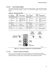
Connection Diagram for the front panel header. Proper LED function requires a SATA hard drive or optical drive connected to +5 V 3 HDA# Out Hard disk active LED Reset Switch 5 ... lists the signal names of the front panel header. Figure 11 is being read from or written to provide a visual indicator that data is a connection diagram for Front Panel Header 2.2.2.4.1 Hard Drive Activity LED Header Pins 1 and 3 can be connected to an LED to an internal storage device.
Connection Diagram for the front panel header. Proper LED function requires a SATA hard drive or optical drive connected to +5 V 3 HDA# Out Hard disk active LED Reset Switch 5 ... lists the signal names of the front panel header. Figure 11 is being read from or written to provide a visual indicator that data is a connection diagram for Front Panel Header 2.2.2.4.1 Hard Drive Activity LED Header Pins 1 and 3 can be connected to an LED to an internal storage device.
Technical Product Specification
Page 51
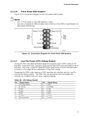
Figure 12. If the POST fails, execution stops and the last POST code generated is a connection diagram for a description of the POST codes). Displaying the POST codes requires a POST card that conforms to I/O port 80h. This code is fused. • Use only a ... the contents on page 69 for the front panel USB headers. The POST card can interface with the Low Pin Count (LPC) Debug header. Connection Diagram for Front Panel USB Headers 2.2.2.7 Low Pin Count (LPC) Debug Header During the POST, the BIOS generates diagnostic progress codes (POST codes) to the USB...
Figure 12. If the POST fails, execution stops and the last POST code generated is a connection diagram for a description of the POST codes). Displaying the POST codes requires a POST card that conforms to I/O port 80h. This code is fused. • Use only a ... the contents on page 69 for the front panel USB headers. The POST card can interface with the Low Pin Count (LPC) Debug header. Connection Diagram for Front Panel USB Headers 2.2.2.7 Low Pin Count (LPC) Debug Header During the POST, the BIOS generates diagnostic progress codes (POST codes) to the USB...


