
Technical Product Specification
Page 2
... Information Technology Equipment (I.T.E.) for use in personal computers (PC) for conflicts or incompatibilities arising from future changes to only the standard Intel® Desktop Board DH61BE with BIOS identifier BEH6110H.86A. Intel desktop boards may contain design defects or errors known as the property of any features or instructions marked "reserved" or "undefined." EXCEPT...
... Information Technology Equipment (I.T.E.) for use in personal computers (PC) for conflicts or incompatibilities arising from future changes to only the standard Intel® Desktop Board DH61BE with BIOS identifier BEH6110H.86A. Intel desktop boards may contain design defects or errors known as the property of any features or instructions marked "reserved" or "undefined." EXCEPT...
Technical Product Specification
Page 3
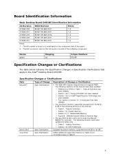
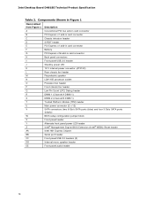
...; The two SATA 6 Gb/s ports are through the Marvell 88SE971X controller. Board Identification Information Basic Desktop Board DH61BE Identification Information AA Revision BIOS Revision Notes G14062-209 BEH6110H.86A.0041 1,2 G14062-210 BEH6110H.86A.0041 1,2 G14063-204 BEH6110H.86A.0016 ... Memory ― Section 2.1.1 Addressable Memory ― Figure 8. The following sections have been updated: ― Reference to the Intel® Desktop Board DH61BE. iii Feature Summary ― Section 1.9 SATA Interfaces Updated maximum memory supported from 16 GB to 8 GB in the following ...
...; The two SATA 6 Gb/s ports are through the Marvell 88SE971X controller. Board Identification Information Basic Desktop Board DH61BE Identification Information AA Revision BIOS Revision Notes G14062-209 BEH6110H.86A.0041 1,2 G14062-210 BEH6110H.86A.0041 1,2 G14063-204 BEH6110H.86A.0016 ... Memory ― Section 2.1.1 Addressable Memory ― Figure 8. The following sections have been updated: ― Reference to the Intel® Desktop Board DH61BE. iii Feature Summary ― Section 1.9 SATA Interfaces Updated maximum memory supported from 16 GB to 8 GB in the following ...
Technical Product Specification
Page 5
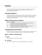
... is intended to provide detailed, technical information about the conventions used on the Intel Desktop Board DH61BE A map of the resources of the Intel Desktop Board The features supported by the BIOS Setup program A description of information. Notes, Cautions, and Warnings NOTE Notes call...and abbreviations appear in this level of the BIOS error messages, beep codes, and POST codes Regulatory compliance and battery disposal information Typographical Conventions This section contains information about the Intel Desktop Board DH61BE and its components to the vendors, system integrators...
... is intended to provide detailed, technical information about the conventions used on the Intel Desktop Board DH61BE A map of the resources of the Intel Desktop Board The features supported by the BIOS Setup program A description of information. Notes, Cautions, and Warnings NOTE Notes call...and abbreviations appear in this level of the BIOS error messages, beep codes, and POST codes Regulatory compliance and battery disposal information Typographical Conventions This section contains information about the Intel Desktop Board DH61BE and its components to the vendors, system integrators...
Technical Product Specification
Page 8
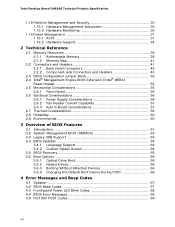
Intel Desktop Board DH61BE Technical Product Specification 1.15 Platform Management and Security 30 1.15.1 Hardware Management Subsystem 30 1.15.2 Hardware Monitoring 30 1.16 Power Management ... Memory 39 2.1.2 Memory Map 41 2.2 Connectors and Headers 41 2.2.1 Back Panel Connectors 42 2.2.2 Component-side Connectors and Headers 43 2.3 BIOS Configuration Jumper Block 52 2.4 Intel® Management Engine BIOS Extension (Intel® MEBX) Reset Header 54 2.5 Mechanical Considerations 55 2.5.1 Form Factor 55 2.6 Electrical Considerations 56 2.6.1 Power Supply Considerations 56 2.6.2 ...
Intel Desktop Board DH61BE Technical Product Specification 1.15 Platform Management and Security 30 1.15.1 Hardware Management Subsystem 30 1.15.2 Hardware Monitoring 30 1.16 Power Management ... Memory 39 2.1.2 Memory Map 41 2.2 Connectors and Headers 41 2.2.1 Back Panel Connectors 42 2.2.2 Component-side Connectors and Headers 43 2.3 BIOS Configuration Jumper Block 52 2.4 Intel® Management Engine BIOS Extension (Intel® MEBX) Reset Header 54 2.5 Mechanical Considerations 55 2.5.1 Form Factor 55 2.6 Electrical Considerations 56 2.6.1 Power Supply Considerations 56 2.6.2 ...
Technical Product Specification
Page 10
...54 29. BIOS Setup Program Menu Bar 62 34. BIOS Beep Codes 67 38. Fan Headers 47 21. States for AC '97 Audio 46 17. LPC Debug Header 51 27. Typical Port 80h POST Sequence 74 43. Alternate Front Panel Power LED Header 50 26. Intel Desktop Board DH61BE Technical Product ...Specification 16. Processor Core Power Connector 48 22. SATA Connectors 46 19. BIOS Setup Configuration Jumper Settings 53 28.
...54 29. BIOS Setup Program Menu Bar 62 34. BIOS Beep Codes 67 38. Fan Headers 47 21. States for AC '97 Audio 46 17. LPC Debug Header 51 27. Typical Port 80h POST Sequence 74 43. Alternate Front Panel Power LED Header 50 26. Intel Desktop Board DH61BE Technical Product ...Specification 16. Processor Core Power Connector 48 22. SATA Connectors 46 19. BIOS Setup Configuration Jumper Settings 53 28.
Technical Product Specification
Page 12
Intel Desktop Board DH61BE Technical Product Specification Table 1. Feature Summary (continued) Peripheral Interfaces Legacy I/O Control BIOS • Twelve USB ports: ― Two USB 3.0 ports are implemented with stacked back panel connectors (blue) ― Two USB 2.0 ports... on back panel • Nuvoton* W83677HG-i Super I/O controller for hardware management and serial port, parallel port, and PS/2 support • Intel® BIOS resident in the SPI Flash device • Support for Advanced Configuration and Power Interface (ACPI), Plug and Play, and SMBIOS Instantly Available PC ...
Intel Desktop Board DH61BE Technical Product Specification Table 1. Feature Summary (continued) Peripheral Interfaces Legacy I/O Control BIOS • Twelve USB ports: ― Two USB 3.0 ports are implemented with stacked back panel connectors (blue) ― Two USB 2.0 ports... on back panel • Nuvoton* W83677HG-i Super I/O controller for hardware management and serial port, parallel port, and PS/2 support • Intel® BIOS resident in the SPI Flash device • Support for Advanced Configuration and Power Interface (ACPI), Plug and Play, and SMBIOS Instantly Available PC ...
Technical Product Specification
Page 14
... 3 Gb/s SATA ports (black)) BIOS setup configuration jumper block Front panel header Alternate front panel power LED header Intel® Management Engine BIOS Extension (Intel® MEBX) Reset header Intel H61 Express Chipset Serial port header Front panel USB 2.0 headers (3) Internal mono speaker header Front panel audio header 14 Intel Desktop Board DH61BE Technical Product Specification Table 2.
... 3 Gb/s SATA ports (black)) BIOS setup configuration jumper block Front panel header Alternate front panel power LED header Intel® Management Engine BIOS Extension (Intel® MEBX) Reset header Intel H61 Express Chipset Serial port header Front panel USB 2.0 headers (3) Internal mono speaker header Front panel audio header 14 Intel Desktop Board DH61BE Technical Product Specification Table 2.
Technical Product Specification
Page 16
... Board products, with a maximum TDP of 95 W. Intel Desktop Board DH61BE Desktop Board Support Available configurations for this World Wide Web site: http://www.intel.com/products/motherboard/index.htm http://www.intel.com/p/en_US/support?iid=hdr+support http://ark.intel.com Supported processors Chipset information BIOS and driver updates Tested memory Integration information http...
... Board products, with a maximum TDP of 95 W. Intel Desktop Board DH61BE Desktop Board Support Available configurations for this World Wide Web site: http://www.intel.com/products/motherboard/index.htm http://www.intel.com/p/en_US/support?iid=hdr+support http://ark.intel.com Supported processors Chipset information BIOS and driver updates Tested memory Integration information http...
Technical Product Specification
Page 17
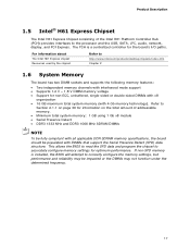
... specifications, the board should be impacted or the DIMMs may be populated with 4 Gb memory technology). For information about The Intel H61 Express chipset Resources used by the chipset Refer to correctly configure the memory settings, but performance and reliability may not function... under the determined frequency. 17 The PCH is installed, the BIOS will attempt to http://www.intel.com/products/desktop/chipsets/index.htm Chapter 2 1.6 System Memory The board has two DIMM sockets and supports the following...
... specifications, the board should be impacted or the DIMMs may be populated with 4 Gb memory technology). For information about The Intel H61 Express chipset Resources used by the chipset Refer to correctly configure the memory settings, but performance and reliability may not function... under the determined frequency. 17 The PCH is installed, the BIOS will attempt to http://www.intel.com/products/desktop/chipsets/index.htm Chapter 2 1.6 System Memory The board has two DIMM sockets and supports the following...
Technical Product Specification
Page 20
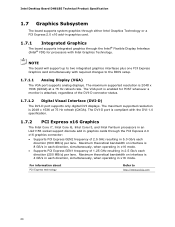
...20 The DVI-D port is 2048 x 1536 at a 75 Hz refresh rate. For information about PCI Express technology Refer to the BIOS setup. 1.7.1.1 Analog Display (VGA) The VGA port supports analog displays. The maximum supported resolution is compliant with the DVI 1.0 specification....frequency of 1.25 GHz resulting in 5.0 Gb/s each direction (500 MB/s) per lane. Intel Desktop Board DH61BE Technical Product Specification 1.7 Graphics Subsystem The board supports system graphics through either Intel Graphics Technology or a PCI Express 2.0 x16 add-in x16 mode. NOTE The board will ...
...20 The DVI-D port is 2048 x 1536 at a 75 Hz refresh rate. For information about PCI Express technology Refer to the BIOS setup. 1.7.1.1 Analog Display (VGA) The VGA port supports analog displays. The maximum supported resolution is compliant with the DVI 1.0 specification....frequency of 1.25 GHz resulting in 5.0 Gb/s each direction (500 MB/s) per lane. Intel Desktop Board DH61BE Technical Product Specification 1.7 Graphics Subsystem The board supports system graphics through either Intel Graphics Technology or a PCI Express 2.0 x16 add-in x16 mode. NOTE The board will ...
Technical Product Specification
Page 22
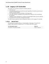
The serial port supports data transfers at speeds up event interface • Conventional PCI bus power management support The BIOS Setup program provides configuration options for the Legacy I /O Controller provides the following features: • One serial port •...style keyboard/mouse interface on the board. For information about The location of the serial port header Refer to 115.2 kbits/s with BIOS support. Intel Desktop Board DH61BE Technical Product Specification 1.10 Legacy I/O Controller The Legacy I /O controller. 1.10.1 Serial Port The serial port is implemented as a...
The serial port supports data transfers at speeds up event interface • Conventional PCI bus power management support The BIOS Setup program provides configuration options for the Legacy I /O Controller provides the following features: • One serial port •...style keyboard/mouse interface on the board. For information about The location of the serial port header Refer to 115.2 kbits/s with BIOS support. Intel Desktop Board DH61BE Technical Product Specification 1.10 Legacy I/O Controller The Legacy I /O controller. 1.10.1 Serial Port The serial port is implemented as a...
Technical Product Specification
Page 28
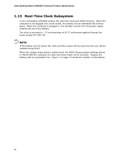
... 25 ºC with an equivalent one. When the voltage drops below a certain level, the BIOS Setup program settings stored in , the standby current from the power supply extends the life of the battery. 28 Intel Desktop Board DH61BE Technical Product Specification 1.13 Real-Time Clock Subsystem A coin-cell battery (CR2032) powers the real...
... 25 ºC with an equivalent one. When the voltage drops below a certain level, the BIOS Setup program settings stored in , the standby current from the power supply extends the life of the battery. 28 Intel Desktop Board DH61BE Technical Product Specification 1.13 Real-Time Clock Subsystem A coin-cell battery (CR2032) powers the real...
Technical Product Specification
Page 30
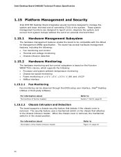
...Chassis Intrusion and Detection The board supports a chassis security feature that attaches to be observed through the BIOS setup user interface, Intel® Desktop Utilities or third-party software. These system management functions are designed to report errors, ... Fan Monitoring Fan monitoring can be compatible with the Wired for Management (WfM) specification. Intel Desktop Board DH61BE Technical Product Specification 1.15 Platform Management and Security Intel DH61BE Desktop Board integrates several hardware management features, including the following: • Fan monitoring and...
...Chassis Intrusion and Detection The board supports a chassis security feature that attaches to be observed through the BIOS setup user interface, Intel® Desktop Utilities or third-party software. These system management functions are designed to report errors, ... Fan Monitoring Fan monitoring can be compatible with the Wired for Management (WfM) specification. Intel Desktop Board DH61BE Technical Product Specification 1.15 Platform Management and Security Intel DH61BE Desktop Board integrates several hardware management features, including the following: • Fan monitoring and...
Technical Product Specification
Page 34
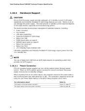
...power through system control. When an ACPI-enabled system receives the correct command, the power supply removes all non-standby voltages. Intel Desktop Board DH61BE Technical Product Specification 1.16.2 Hardware Support CAUTION Ensure that provides full ACPI support. 1.16.2.1 Power Connector ATX12V-compliant power ...and Instantly Available PC technology require power from an AC power failure, the computer returns to the power state it was in the BIOS Setup program's Boot menu. When resuming from the +5 V standby line. The total amount of the main power connector Refer ...
...power through system control. When an ACPI-enabled system receives the correct command, the power supply removes all non-standby voltages. Intel Desktop Board DH61BE Technical Product Specification 1.16.2 Hardware Support CAUTION Ensure that provides full ACPI support. 1.16.2.1 Power Connector ATX12V-compliant power ...and Instantly Available PC technology require power from an AC power failure, the computer returns to the power state it was in the BIOS Setup program's Boot menu. When resuming from the +5 V standby line. The total amount of the main power connector Refer ...
Technical Product Specification
Page 36
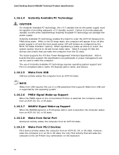
...computer from an ACPI S3 state. 1.16.2.9 Wake from PS/2 Devices PS/2 device activity wakes the computer from the S3 state. Intel Desktop Board DH61BE Technical Product Specification 1.16.2.4 Instantly Available PC Technology CAUTION For Instantly Available PC technology, the +5 V standby line for the power ...supply must be off (the power supply is off and the front panel power LED will behave as configured by the BIOS "S3 ...
...computer from an ACPI S3 state. 1.16.2.9 Wake from PS/2 Devices PS/2 device activity wakes the computer from the S3 state. Intel Desktop Board DH61BE Technical Product Specification 1.16.2.4 Instantly Available PC Technology CAUTION For Instantly Available PC technology, the +5 V standby line for the power ...supply must be off (the power supply is off and the front panel power LED will behave as configured by the BIOS "S3 ...
Technical Product Specification
Page 39
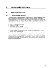
... bus add-in cards (256 MB) The board provides the capability to use all of the system memory map. These functions include the following: • BIOS/SPI Flash device (32 Mbit) • Local APIC (19 MB) • Direct Media Interface (40 MB) • PCI Express configuration space (256 ... overlap of addressable system memory. On a system that is allocated for Conventional PCI and PCI Express add-in cards, PCI Express configuration space, BIOS (SPI Flash device), and chipset overhead resides above the 4 GB boundary. All installed system memory can be used when there is not possible...
... bus add-in cards (256 MB) The board provides the capability to use all of the system memory map. These functions include the following: • BIOS/SPI Flash device (32 Mbit) • Local APIC (19 MB) • Direct Media Interface (40 MB) • PCI Express configuration space (256 ... overlap of addressable system memory. On a system that is allocated for Conventional PCI and PCI Express add-in cards, PCI Express configuration space, BIOS (SPI Flash device), and chipset overhead resides above the 4 GB boundary. All installed system memory can be used when there is not possible...
Technical Product Specification
Page 41
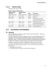
... 41 The connectors can be divided into these connectors or headers to power devices external to the computer's chassis. Video memory and BIOS Extended BIOS data (movable by the external devices could cause damage to the PCI bus). The other internal connectors and headers are not overcurrent protected...- 9FBFF 00000 - 7FFFF Size 16382 MB 64 KB 64 KB 96 KB 160 KB 1 KB 127 KB 512 KB Description Extended memory Runtime BIOS Reserved Potential available high DOS memory (open to the computer, the power cable, and the external devices themselves. Dependent on video adapter used. Table...
... 41 The connectors can be divided into these connectors or headers to power devices external to the computer's chassis. Video memory and BIOS Extended BIOS data (movable by the external devices could cause damage to the PCI bus). The other internal connectors and headers are not overcurrent protected...- 9FBFF 00000 - 7FFFF Size 16382 MB 64 KB 64 KB 96 KB 160 KB 1 KB 127 KB 512 KB Description Extended memory Runtime BIOS Reserved Potential available high DOS memory (open to the computer, the power cable, and the external devices themselves. Dependent on video adapter used. Table...
Technical Product Specification
Page 50
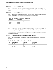
More options are available through BIOS setup. States for this header duplicate the signals on /off signal. 2.2.2.5 Alternate Front Panel Power LED Header Pins 1 and 3 of the front panel header. Table ... switch on or off /sleeping Steady Lit Running Blink Standby 2.2.2.4.4 Power Switch Header Pins 6 and 8 can be connected to a front panel momentary-contact power switch. Intel Desktop Board DH61BE Technical Product Specification 2.2.2.4.2 Reset Switch Header Pins 5 and 7 can be connected to a one- or two-color LED.
More options are available through BIOS setup. States for this header duplicate the signals on /off signal. 2.2.2.5 Alternate Front Panel Power LED Header Pins 1 and 3 of the front panel header. Table ... switch on or off /sleeping Steady Lit Running Blink Standby 2.2.2.4.4 Power Switch Header Pins 6 and 8 can be connected to a front panel momentary-contact power switch. Intel Desktop Board DH61BE Technical Product Specification 2.2.2.4.2 Reset Switch Header Pins 5 and 7 can be connected to a one- or two-color LED.
Technical Product Specification
Page 51
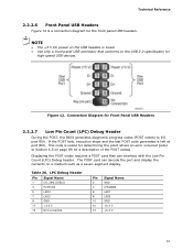
... where an error occurred (refer to I/O port 80h. Connection Diagram for Front Panel USB Headers 2.2.2.7 Low Pin Count (LPC) Debug Header During the POST, the BIOS generates diagnostic progress codes (POST codes) to Section 4.5 on page 69 for high-speed USB devices. If the POST fails, execution stops and the last...
... where an error occurred (refer to I/O port 80h. Connection Diagram for Front Panel USB Headers 2.2.2.7 Low Pin Count (LPC) Debug Header During the POST, the BIOS generates diagnostic progress codes (POST codes) to Section 4.5 on page 69 for high-speed USB devices. If the POST fails, execution stops and the last...
Technical Product Specification
Page 52
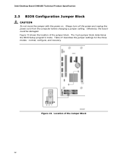
Figure 13. Location of the jumper block. Intel Desktop Board DH61BE Technical Product Specification 2.3 BIOS Configuration Jumper Block CAUTION Do not move the jumper with the power on. Table 27 describes the jumper settings for the three modes: normal, configure, and recovery. Figure 13 shows the location of the Jumper Block 52 The 3-pin jumper block determines the BIOS Setup program's mode. Otherwise, the board could be damaged. Always turn off the power and unplug the power cord from the computer before changing a jumper setting.
Figure 13. Location of the jumper block. Intel Desktop Board DH61BE Technical Product Specification 2.3 BIOS Configuration Jumper Block CAUTION Do not move the jumper with the power on. Table 27 describes the jumper settings for the three modes: normal, configure, and recovery. Figure 13 shows the location of the Jumper Block 52 The 3-pin jumper block determines the BIOS Setup program's mode. Otherwise, the board could be damaged. Always turn off the power and unplug the power cord from the computer before changing a jumper setting.


