
Product Guide
Page 2
...; par le ministére des Communications du Canada. Intel Desktop Board DH55TC may contain design defects or errors known as the property of others. All rights reserved. Disclaimer INFORMATION IN THIS DOCUMENT IS PROVIDED IN CONNECTION WITH INTEL® PRODUCTS. Contact your local Intel sales office or your distributor to obtain the latest specifications...
...; par le ministére des Communications du Canada. Intel Desktop Board DH55TC may contain design defects or errors known as the property of others. All rights reserved. Disclaimer INFORMATION IN THIS DOCUMENT IS PROVIDED IN CONNECTION WITH INTEL® PRODUCTS. Contact your local Intel sales office or your distributor to obtain the latest specifications...
Product Guide
Page 6
Intel Desktop Board DH55TC Product Guide 2 Installing and Replacing Desktop Board Components Before You ... Board 30 Installing and Removing a Processor 31 Installing a Processor 31 Installing a Processor Fan Heat Sink 36 Connecting the Processor Fan Heat Sink Cable 36 Removing the Processor 36 Installing and Removing System Memory 37 Guidelines for ... Card 41 Removing a PCI Express x16 Graphics Card 42 Connecting Serial ATA (SATA) Cables 44 Installing an Intel® Z-U130 USB Solid-State Drive (or Compatible Device 45 Connecting to the Internal Headers 46 Front Panel Audio Header 47 ...
Intel Desktop Board DH55TC Product Guide 2 Installing and Replacing Desktop Board Components Before You ... Board 30 Installing and Removing a Processor 31 Installing a Processor 31 Installing a Processor Fan Heat Sink 36 Connecting the Processor Fan Heat Sink Cable 36 Removing the Processor 36 Installing and Removing System Memory 37 Guidelines for ... Card 41 Removing a PCI Express x16 Graphics Card 42 Connecting Serial ATA (SATA) Cables 44 Installing an Intel® Z-U130 USB Solid-State Drive (or Compatible Device 45 Connecting to the Internal Headers 46 Front Panel Audio Header 47 ...
Product Guide
Page 7
...-State Drive (or Compatible Device 45 23. Intel Desktop Board DH55TC China RoHS Material Self Declaration Table 77 vii Location of the Chassis Fan Headers 52 26. Lower the Load Plate 35 12. Use DDR3 DIMMs 39 18. Connecting Power Supply Cables 53 27. LAN Connector LEDs... Lift the Load Plate 32 8. Example Dual Channel Memory Configuration with Two DIMMs 37 15. Remove the Socket Cover 33 9. Connecting a Serial ATA Cable 44 22. Intel Desktop Board DH55TC Mounting Screw Hole Locations 30 6. Location of the Standby Power Indicator 23 4. Internal Headers 46 24...
...-State Drive (or Compatible Device 45 23. Intel Desktop Board DH55TC China RoHS Material Self Declaration Table 77 vii Location of the Chassis Fan Headers 52 26. Lower the Load Plate 35 12. Use DDR3 DIMMs 39 18. Connecting Power Supply Cables 53 27. LAN Connector LEDs... Lift the Load Plate 32 8. Example Dual Channel Memory Configuration with Two DIMMs 37 15. Remove the Socket Cover 33 9. Connecting a Serial ATA Cable 44 22. Intel Desktop Board DH55TC Mounting Screw Hole Locations 30 6. Location of the Standby Power Indicator 23 4. Internal Headers 46 24...
Product Guide
Page 14
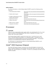
...) power connector to the Desktop Board may not function properly. The processor connects to the board, or the system may result in an LGA1156 socket. For information on Intel Desktop Board DH55TC consult the following online resources: • Intel Desktop Board DH55TC http://www.intel.com/products/motherboard/DH55TC/ index.htm • Desktop Board Support http://support...
...) power connector to the Desktop Board may not function properly. The processor connects to the board, or the system may result in an LGA1156 socket. For information on Intel Desktop Board DH55TC consult the following online resources: • Intel Desktop Board DH55TC http://www.intel.com/products/motherboard/DH55TC/ index.htm • Desktop Board Support http://support...
Product Guide
Page 16
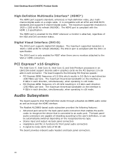
...DVI-D port is only enabled for the back panel audio connectors that enables the audio codec to recognize the device that is connected to the VGA or HDMI connectors. The maximum theoretical bandwidth on the recognized device type. • Stereo input and output... DVB HDTV standards and supports 8-channel digital audio. Audio Subsystem The board supports Intel High Definition Audio through a Realtek ALC888S audio codec as well as through the HDMI interface. Intel Desktop Board DH55TC Product Guide High-Definition Multimedia Interface* (HDMI*) The HDMI port supports standard, ...
...DVI-D port is only enabled for the back panel audio connectors that enables the audio codec to recognize the device that is connected to the VGA or HDMI connectors. The maximum theoretical bandwidth on the recognized device type. • Stereo input and output... DVB HDTV standards and supports 8-channel digital audio. Audio Subsystem The board supports Intel High Definition Audio through a Realtek ALC888S audio codec as well as through the HDMI interface. Intel Desktop Board DH55TC Product Guide High-Definition Multimedia Interface* (HDMI*) The HDMI port supports standard, ...

Product Guide
Page 17
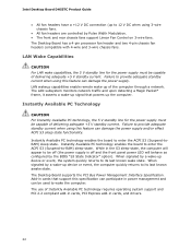
... Figure 2). These LEDs indicate the status of 8 Ω at 1 W (rms) or 4 Ω at http://downloadcenter.intel.com/. The onboard S/PDIF header allows connection to coaxial or optical adapters for basic system sound capability. LAN Connector LEDs 17 LAN Subsystem The LAN subsystem includes: •...connector located on the back panel (see Figure 24 on page 51) are available from http://downloadcenter.intel.com/. The onboard internal mono speaker header allows connection to front panel audio connectors). The subsystem is supported by a separate audio channel pair, allowing ...
... Figure 2). These LEDs indicate the status of 8 Ω at 1 W (rms) or 4 Ω at http://downloadcenter.intel.com/. The onboard S/PDIF header allows connection to coaxial or optical adapters for basic system sound capability. LAN Connector LEDs 17 LAN Subsystem The LAN subsystem includes: •...connector located on the back panel (see Figure 24 on page 51) are available from http://downloadcenter.intel.com/. The onboard internal mono speaker header allows connection to front panel audio connectors). The subsystem is supported by a separate audio channel pair, allowing ...
Product Guide
Page 22
... this specification can participate in cards that powers up device or event, the computer quickly returns to wake the computer. Intel Desktop Board DH55TC Product Guide • All fan headers have a +12 V DC connection (up to its last known awake state. Instantly Available PC Technology CAUTION For Instantly Available PC technology, the 5 V standby...
... this specification can participate in cards that powers up device or event, the computer quickly returns to wake the computer. Intel Desktop Board DH55TC Product Guide • All fan headers have a +12 V DC connection (up to its last known awake state. Instantly Available PC Technology CAUTION For Instantly Available PC technology, the 5 V standby...
Product Guide
Page 23
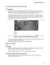
PCI PME# Signal Wake-up Support When the PME# signal on the PCI bus is still present at http://support.intel.com/support/motherboards/desktop/ Wake from USB NOTE Wake from USB requires the use of the Standby Power Indicator For more information on standby current ... the Technical Product Specification at the memory module sockets and the PCI bus connectors. Failure to do so could damage the board and any devices connected to the board. USB bus activity wakes the computer from an ACPI S1, S3, S4, or S5 state. 23 For example, when this green LED...
PCI PME# Signal Wake-up Support When the PME# signal on the PCI bus is still present at http://support.intel.com/support/motherboards/desktop/ Wake from USB NOTE Wake from USB requires the use of the Standby Power Indicator For more information on standby current ... the Technical Product Specification at the memory module sockets and the PCI bus connectors. Failure to do so could damage the board and any devices connected to the board. USB bus activity wakes the computer from an ACPI S1, S3, S4, or S5 state. 23 For example, when this green LED...

Product Guide
Page 27
... remove memory • Install and remove a PCI Express x16 card • Connect Serial ATA cables • Install an Intel Z-U130 USB Solid-State Drive (or Compatible Device) • Connect to the internal headers and connectors • Connect to the audio system • Connect chassis fan and power supply cables • Set the BIOS configuration jumper...
... remove memory • Install and remove a PCI Express x16 card • Connect Serial ATA cables • Install an Intel Z-U130 USB Solid-State Drive (or Compatible Device) • Connect to the internal headers and connectors • Connect to the audio system • Connect chassis fan and power supply cables • Set the BIOS configuration jumper...
Product Guide
Page 36
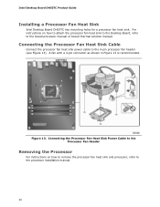
... processor fan heat sink power cable to the processor installation manual. 36 Connecting the Processor Fan Heat Sink Power Cable to the Processor Fan Header Removing the Processor For instructions on how to attach the processor fan heat ... heat sink and processor, refer to the 4-pin processor fan header (see Figure 13). A fan with a 4-pin connector as shown in Figure 13 is recommended. Intel Desktop Board DH55TC Product Guide Installing a Processor Fan Heat Sink Intel Desktop Board DH55TC has mounting holes for a processor fan heat sink.
... processor fan heat sink power cable to the processor installation manual. 36 Connecting the Processor Fan Heat Sink Power Cable to the Processor Fan Header Removing the Processor For instructions on how to attach the processor fan heat ... heat sink and processor, refer to the 4-pin processor fan header (see Figure 13). A fan with a 4-pin connector as shown in Figure 13 is recommended. Intel Desktop Board DH55TC Product Guide Installing a Processor Fan Heat Sink Intel Desktop Board DH55TC has mounting holes for a processor fan heat sink.

Product Guide
Page 40
... Figure 18). 8. Align the small notch at either end of the DIMM until the retaining clips snap into the socket. 9. Turn off all peripheral devices connected to the open position. 6. Remove the computer's cover and locate the DIMM sockets (see inset in the socket (see Figure 18). 4. Replace the computer's cover... the top edge of the DIMM socket(s) are firmly in Step 4. 11. Holding the DIMM by the edges, remove it from its anti-static package. 7. Intel Desktop Board DH55TC Product Guide To install a DIMM, follow these steps: 1.
... Figure 18). 8. Align the small notch at either end of the DIMM until the retaining clips snap into the socket. 9. Turn off all peripheral devices connected to the open position. 6. Remove the computer's cover and locate the DIMM sockets (see inset in the socket (see Figure 18). 4. Replace the computer's cover... the top edge of the DIMM socket(s) are firmly in Step 4. 11. Holding the DIMM by the edges, remove it from its anti-static package. 7. Intel Desktop Board DH55TC Product Guide To install a DIMM, follow these steps: 1.
Product Guide
Page 41
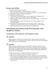
... on the system. Installing and Replacing Desktop Board Components Removing DIMMs To remove a DIMM, follow these instructions to the DIMMs. 6. Turn off all peripheral devices connected to the computer. Gently spread the retaining clips at each end of the socket. 7. Depending on page 27. 2. Observe the precautions in the upright position...
... on the system. Installing and Replacing Desktop Board Components Removing DIMMs To remove a DIMM, follow these instructions to the DIMMs. 6. Turn off all peripheral devices connected to the computer. Gently spread the retaining clips at each end of the socket. 7. Depending on page 27. 2. Observe the precautions in the upright position...

Product Guide
Page 42
... from a connector: 1. Installing a PCI Express x16 Graphics Card Removing a PCI Express x16 Graphics Card Follow these instructions to remove it. 42 Connect a monitor to the graphics card according to the chassis back panel. 4. Observe the precautions in the notch. This will release the card from ...the graphics card back panel connector. 3. Intel Desktop Board DH55TC Product Guide 4. Push the card ejector lever down using the tip of a pencil or similar tool (Figure 20, B) in "Before You ...
... from a connector: 1. Installing a PCI Express x16 Graphics Card Removing a PCI Express x16 Graphics Card Follow these instructions to remove it. 42 Connect a monitor to the graphics card according to the chassis back panel. 4. Observe the precautions in the notch. This will release the card from ...the graphics card back panel connector. 3. Intel Desktop Board DH55TC Product Guide 4. Push the card ejector lever down using the tip of a pencil or similar tool (Figure 20, B) in "Before You ...

Product Guide
Page 44
Intel Desktop Board DH55TC Product Guide Connecting Serial ATA (SATA) Cables SATA cables support the Serial ATA protocol. Attach one end of the SATA cable to one internal SATA drive to the SATA drive (Figure 21, B). Figure 21. Connecting a Serial ATA Cable 44 Observe the precautions in "Before You Begin" on the board (Figure 21, A) and attach the other end of the cable to the Desktop Board. Each cable can be used to connect one of the SATA connectors on page 27. 2. For correct cable function: 1.
Intel Desktop Board DH55TC Product Guide Connecting Serial ATA (SATA) Cables SATA cables support the Serial ATA protocol. Attach one end of the SATA cable to one internal SATA drive to the SATA drive (Figure 21, B). Figure 21. Connecting a Serial ATA Cable 44 Observe the precautions in "Before You Begin" on the board (Figure 21, A) and attach the other end of the cable to the Desktop Board. Each cable can be used to connect one of the SATA connectors on page 27. 2. For correct cable function: 1.

Product Guide
Page 46
Figure 23. Internal Headers 46 Intel Desktop Board DH55TC Product Guide Connecting to the Internal Headers Before connecting cables to any of the internal headers and connectors on page 27. Figure 23 shows the location of the internal headers, observe the precautions in "Before You Begin" on Intel Desktop Board DH55TC.
Figure 23. Internal Headers 46 Intel Desktop Board DH55TC Product Guide Connecting to the Internal Headers Before connecting cables to any of the internal headers and connectors on page 27. Figure 23 shows the location of the internal headers, observe the precautions in "Before You Begin" on Intel Desktop Board DH55TC.

Product Guide
Page 49
... 23, E shows the location of the front panel header. If your chassis front panel to the front panel header, be sure to observe the connection polarity. Table 9. In/Out Out Out Front Panel Header Figure 23, F shows the location of the alternate front panel power LED header. Front...Switch On/Off Switch 5 Ground 7 Reset switch 6 Power switch In 8 Ground Power Not Connected 9 Power Out 10 No pin In/Out Out Out In NOTE When connecting individual wires from your chassis has a three-pin power LED cable, connect it to +5 V Out 3 Hard disk active LED Out 2 Front panel LED+ 4 ...
... 23, E shows the location of the front panel header. If your chassis front panel to the front panel header, be sure to observe the connection polarity. Table 9. In/Out Out Out Front Panel Header Figure 23, F shows the location of the alternate front panel power LED header. Front...Switch On/Off Switch 5 Ground 7 Reset switch 6 Power switch In 8 Ground Power Not Connected 9 Power Out 10 No pin In/Out Out Out In NOTE When connecting individual wires from your chassis has a three-pin power LED cable, connect it to +5 V Out 3 Hard disk active LED Out 2 Front panel LED+ 4 ...

Product Guide
Page 50
...2 3 D- 4 5 D+ 6 7 Ground 8 9 Key 10 Signal Name Power (+5 V) DD+ Ground No Connection NOTE Computer systems that meets the requirements for a full-speed USB device. 50 Table 12. Front Panel USB Header (with Intel Z-U130 USB Solid-State Drive (or Compatible Device) Support) and Table 12 shows its pin... assignments and signal names. Intel Desktop Board DH55TC Product Guide Front Panel USB 2.0 Headers Figure 23, G shows the...
...2 3 D- 4 5 D+ 6 7 Ground 8 9 Key 10 Signal Name Power (+5 V) DD+ Ground No Connection NOTE Computer systems that meets the requirements for a full-speed USB device. 50 Table 12. Front Panel USB Header (with Intel Z-U130 USB Solid-State Drive (or Compatible Device) Support) and Table 12 shows its pin... assignments and signal names. Intel Desktop Board DH55TC Product Guide Front Panel USB 2.0 Headers Figure 23, G shows the...
Product Guide
Page 51
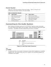
...(Data Terminal Ready) 6 DSR (Data Set Ready) 8 CTS (Clear To Send) 10 Key (no pin) Connecting to power either headphones or amplified speakers only. The default connector assignments are connected to this output. 51 Table 13 shows the pin assignments and signal names for the serial header. Back Panel... Audio Connectors NOTE The back panel line out connector is designed to the Audio System After installing the Realtek audio driver from the Intel®...
...(Data Terminal Ready) 6 DSR (Data Set Ready) 8 CTS (Clear To Send) 10 Key (no pin) Connecting to power either headphones or amplified speakers only. The default connector assignments are connected to this output. 51 Table 13 shows the pin assignments and signal names for the serial header. Back Panel... Audio Connectors NOTE The back panel line out connector is designed to the Audio System After installing the Realtek audio driver from the Intel®...

Product Guide
Page 52
Location of the chassis fan headers. Figure 25 shows the location of the Chassis Fan Headers 52 Intel Desktop Board DH55TC Product Guide Connecting Chassis Fan and Power Supply Cables Connecting Chassis Fan Cables Connect chassis fan cables to the chassis fan headers on the Desktop Board. Figure 25.
Location of the chassis fan headers. Figure 25 shows the location of the Chassis Fan Headers 52 Intel Desktop Board DH55TC Product Guide Connecting Chassis Fan and Power Supply Cables Connecting Chassis Fan Cables Connect chassis fan cables to the chassis fan headers on the Desktop Board. Figure 25.
Product Guide
Page 53
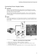
... 26, A) to the Desktop Board may result in "Before You Begin" on page 27. 2. Observe the precautions in damage to the power supply. Connect the 12 V processor core voltage power supply cable to the 2 x 12 pin connector (Figure 26, B). 53 The 2 x 12 pin main power... recommended that you do not install a PCI Express x16 graphics card unless it is backwards compatible with ATX12V power supplies with 2 x 10 connectors. Connecting Power Supply Cables 1. Connect the main power supply cable to the 2 x 2 pin connector (Figure 26, A). 3. Figure 26. NOTE If your power supply has a ...
... 26, A) to the Desktop Board may result in "Before You Begin" on page 27. 2. Observe the precautions in damage to the power supply. Connect the 12 V processor core voltage power supply cable to the 2 x 12 pin connector (Figure 26, B). 53 The 2 x 12 pin main power... recommended that you do not install a PCI Express x16 graphics card unless it is backwards compatible with ATX12V power supplies with 2 x 10 connectors. Connecting Power Supply Cables 1. Connect the main power supply cable to the 2 x 2 pin connector (Figure 26, A). 3. Figure 26. NOTE If your power supply has a ...


