

Product Guide
Page 5
Contents 1 Desktop Board Features Supported Operating Systems 10 Desktop Board Components 11 Processor ...13 Main Memory ...13 Intel® G965 Express Chipset 14 Intel G965 Graphics Subsystem 15 Onboard Audio Subsystem 16 Input/Output (I/O) Controller 17 LAN Subsystem 17 LAN Subsystem Software 17 RJ-45 LAN Connector LEDs 18 ...
Contents 1 Desktop Board Features Supported Operating Systems 10 Desktop Board Components 11 Processor ...13 Main Memory ...13 Intel® G965 Express Chipset 14 Intel G965 Graphics Subsystem 15 Onboard Audio Subsystem 16 Input/Output (I/O) Controller 17 LAN Subsystem 17 LAN Subsystem Software 17 RJ-45 LAN Connector LEDs 18 ...
Product Guide
Page 6
Intel Desktop Board DG965WH Product Guide Installing and Removing a Processor 31 Installing a Processor 31 Installing the Processor Fan Heat Sink 34 Connecting the Processor Fan Heat Sink Cable 34 Removing the Processor 35 Installing and Removing Memory 35 Guidelines for Dual Channel Memory Configuration 35 Two or Four DIMMs... Cable 42 Connecting the Serial ATA (SATA) Cable 43 Connecting to Internal Headers 44 Installing a Front Panel Audio Solution for Intel® High Definition Audio 45 Connecting to the USB 2.0 Headers 46 Connecting to the Front Panel Header 46 Connecting to the...
Intel Desktop Board DG965WH Product Guide Installing and Removing a Processor 31 Installing a Processor 31 Installing the Processor Fan Heat Sink 34 Connecting the Processor Fan Heat Sink Cable 34 Removing the Processor 35 Installing and Removing Memory 35 Guidelines for Dual Channel Memory Configuration 35 Two or Four DIMMs... Cable 42 Connecting the Serial ATA (SATA) Cable 43 Connecting to Internal Headers 44 Installing a Front Panel Audio Solution for Intel® High Definition Audio 45 Connecting to the USB 2.0 Headers 46 Connecting to the Front Panel Header 46 Connecting to the...
Product Guide
Page 7
... 11 2. Close the Load Plate 33 12. Connecting the Processor Fan Heat Sink Cable to the Processor Fan Header.......... 34 13. Installing a PCI Express x16 Card 40 19. Desktop Board DG965WH Mounting Screw Hole Locations 30 6. Dual Channel Memory Configuration Example 1 35 14. Dual ... 3 36 16. Back Panel Audio Connectors 48 24. Removing the Battery 59 vii Contents 5 Intel® Quick Resume Technology Driver (Intel® QRTD) Overview...69 Intel Quick Resume Technology Power Modes 69 Installation and Configuration 70 A Error Messages and Indicators BIOS Beep Codes...
... 11 2. Close the Load Plate 33 12. Connecting the Processor Fan Heat Sink Cable to the Processor Fan Header.......... 34 13. Installing a PCI Express x16 Card 40 19. Desktop Board DG965WH Mounting Screw Hole Locations 30 6. Dual Channel Memory Configuration Example 1 35 14. Dual ... 3 36 16. Back Panel Audio Connectors 48 24. Removing the Battery 59 vii Contents 5 Intel® Quick Resume Technology Driver (Intel® QRTD) Overview...69 Intel Quick Resume Technology Power Modes 69 Installation and Configuration 70 A Error Messages and Indicators BIOS Beep Codes...
Product Guide
Page 9
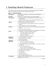
...] x 243.84 millimeters [9.60 inches]) Support for an Intel® processor in the LGA775 package • Four 240-pin, DDR2...Intel® G965 Express Chipset Graphics and Memory Controller Hub (GMCH) • Intel® 82801HH I/O Controller Hub (ICH8DH) • Intel® G965 Express Chipset with Intel® Graphics Media Accelerator X3000 • Intel... • 8-channel (7.1) onboard subsystem, featuring: ― Intel® High Definition Audio interface ― SigmaTel* STAC9271D audio...subsystem using the Intel® 82566DC Gigabit Network Connection continued 9 Table 1. 1 ...
...] x 243.84 millimeters [9.60 inches]) Support for an Intel® processor in the LGA775 package • Four 240-pin, DDR2...Intel® G965 Express Chipset Graphics and Memory Controller Hub (GMCH) • Intel® 82801HH I/O Controller Hub (ICH8DH) • Intel® G965 Express Chipset with Intel® Graphics Media Accelerator X3000 • Intel... • 8-channel (7.1) onboard subsystem, featuring: ― Intel® High Definition Audio interface ― SigmaTel* STAC9271D audio...subsystem using the Intel® 82566DC Gigabit Network Connection continued 9 Table 1. 1 ...
Product Guide
Page 12
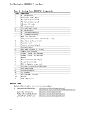
... header Related Links: Go to the following links for more information about: • Desktop Board DG965WH http://www.intel.com/design/motherbd http://support.intel.com/support/motherboards/desktop • Supported processors http://www.intel.com/go/findCPU • Audio software and utilities http://www.intel.com/design/motherbd • LAN software and drivers http://www...
... header Related Links: Go to the following links for more information about: • Desktop Board DG965WH http://www.intel.com/design/motherbd http://support.intel.com/support/motherboards/desktop • Supported processors http://www.intel.com/go/findCPU • Audio software and utilities http://www.intel.com/design/motherbd • LAN software and drivers http://www...

Product Guide
Page 13
...Serial Presence Detect (SPD) data structure. The supported processors list for Desktop Board DG965WH is located on installing or upgrading the processor, page 31 in Chapter 2 Main Memory NOTE To be fully compliant with all applicable Intel® SDRAM memory specifications, the board should be ...modules do not support SPD, you will attempt to the board or the system may result in the LGA775 package. Desktop Board DG965WH supports an Intel processor in damage to configure the memory controller for : ― Unbuffered, non-registered single or double-sided DIMMs ― Non...
...Serial Presence Detect (SPD) data structure. The supported processors list for Desktop Board DG965WH is located on installing or upgrading the processor, page 31 in Chapter 2 Main Memory NOTE To be fully compliant with all applicable Intel® SDRAM memory specifications, the board should be ...modules do not support SPD, you will attempt to the board or the system may result in the LGA775 package. Desktop Board DG965WH supports an Intel processor in damage to configure the memory controller for : ― Unbuffered, non-registered single or double-sided DIMMs ― Non...

Product Guide
Page 19
...-ROM drives. USB 1.1 devices will function normally at USB 1.1 speeds. Enhanced IDE Interface The desktop board's IDE interface handles the exchange of information between the processor and peripheral devices such as CD-ROM drives) • Older PIO Mode devices • Ultra DMA-33 and ATA-66/100 protocols Serial ATA The...
...-ROM drives. USB 1.1 devices will function normally at USB 1.1 speeds. Enhanced IDE Interface The desktop board's IDE interface handles the exchange of information between the processor and peripheral devices such as CD-ROM drives) • Older PIO Mode devices • Ultra DMA-33 and ATA-66/100 protocols Serial ATA The...

Product Guide
Page 21
...Management Features The hardware management features of Desktop Board DG965WH enable the board to be connected to enable Intel® Quiet System Technology. • Fan speed controllers and sensors integrated into the ICH8 • Thermal sensors in the processor, GMCH, and ICH8 plus an onboard remote ...can be compatible with the Wired for the location of power supply voltages to detect levels above and below acceptable values • Intel Quiet System Technology, delivering acoustically-optimized thermal management NOTE Memory must be installed in the Channel A, DIMM 0 socket to the ...
...Management Features The hardware management features of Desktop Board DG965WH enable the board to be connected to enable Intel® Quiet System Technology. • Fan speed controllers and sensors integrated into the ICH8 • Thermal sensors in the processor, GMCH, and ICH8 plus an onboard remote ...can be compatible with the Wired for the location of power supply voltages to detect levels above and below acceptable values • Intel Quiet System Technology, delivering acoustically-optimized thermal management NOTE Memory must be installed in the Channel A, DIMM 0 socket to the ...

Product Guide
Page 22
...wake capabilities ― Instantly Available PC technology (Suspend to a tachometer input of the power connectors. The desktop board has a 4-pin processor fan header, two 3-pin chassis fan headers, and one 4-pin chassis fan header. 22 When resuming from PS/2 keyboard/mouse ―...hardware monitoring and control device • All fan headers support closed-loop fan control that provides full ACPI support. Intel Desktop Board DG965WH Product Guide Power Management Features Power management is implemented at several levels, including: • Software support through system control...
...wake capabilities ― Instantly Available PC technology (Suspend to a tachometer input of the power connectors. The desktop board has a 4-pin processor fan header, two 3-pin chassis fan headers, and one 4-pin chassis fan header. 22 When resuming from PS/2 keyboard/mouse ―...hardware monitoring and control device • All fan headers support closed-loop fan control that provides full ACPI support. Intel Desktop Board DG965WH Product Guide Power Management Features Power management is implemented at several levels, including: • Software support through system control...

Product Guide
Page 27
... Replacing Desktop Board Components This chapter tells you how to: • Install the I/O shield • Install and remove the desktop board • Install and remove a processor • Install and remove memory • Install and remove a PCI Express x16 card • Connect the IDE and Serial ATA cables • Connect to the...
... Replacing Desktop Board Components This chapter tells you how to: • Install the I/O shield • Install and remove the desktop board • Install and remove a processor • Install and remove memory • Install and remove a PCI Express x16 card • Connect the IDE and Serial ATA cables • Connect to the...

Product Guide
Page 28
Intel Desktop Board DG965WH Product Guide Installation Precautions When you install and test the Intel desktop board, observe all warnings and cautions that your computer meets safety and regulatory requirements. Prevent Power Supply Overload Do not overload the power supply ... instructions supplied with regional laws and regulations. Related Links For information about regulatory compliance, go to Appendix B on the chassis • Hot components (such as processors, voltage regulators, and heat sinks) • Damage to qualified technical personnel.
Intel Desktop Board DG965WH Product Guide Installation Precautions When you install and test the Intel desktop board, observe all warnings and cautions that your computer meets safety and regulatory requirements. Prevent Power Supply Overload Do not overload the power supply ... instructions supplied with regional laws and regulations. Related Links For information about regulatory compliance, go to Appendix B on the chassis • Hot components (such as processors, voltage regulators, and heat sinks) • Damage to qualified technical personnel.

Product Guide
Page 31
...instructions: 1. Open the socket lever by unplugging the power cord from the socket (Figure 6, A and B). Figure 6. Failure to install the processor on the desktop board are given below. Do not touch the socket contacts (Figure 7, B). Lift the load plate (Figure 7, A). Lift ... 7. Observe the precautions in "Before You Begin" on page 24). Installing and Replacing Desktop Board Components Installing and Removing a Processor Instructions on how to do so could damage the processor and the board. the standby power LED should not be lit (see Figure 3 on page 27. 2. Installing...
...instructions: 1. Open the socket lever by unplugging the power cord from the socket (Figure 6, A and B). Figure 6. Failure to install the processor on the desktop board are given below. Do not touch the socket contacts (Figure 7, B). Lift the load plate (Figure 7, A). Lift ... 7. Observe the precautions in "Before You Begin" on page 24). Installing and Replacing Desktop Board Components Installing and Removing a Processor Instructions on how to do so could damage the processor and the board. the standby power LED should not be lit (see Figure 3 on page 27. 2. Installing...

Product Guide
Page 32
... protective socket cover from the Protective Processor Cover 32 Always replace the processor cover if the processor is removed from the socket. Intel Desktop Board DG965WH Product Guide 4. Do not discard the protective processor cover. Remove the Protective Socket Cover 5. Figure 9. Remove the Processor from the load plate (see Figure 9). Remove the processor from the socket. Do not...
... protective socket cover from the Protective Processor Cover 32 Always replace the processor cover if the processor is removed from the socket. Intel Desktop Board DG965WH Product Guide 4. Do not discard the protective processor cover. Remove the Protective Socket Cover 5. Figure 9. Remove the Processor from the load plate (see Figure 9). Remove the processor from the socket. Do not...

Product Guide
Page 33
Lower the processor straight down on the load plate (Figure 11, A) close and engage the socket lever (Figure 11, B). Pressing down without tilting or sliding the processor in Figure 10. Make sure fingers align to the socket cutouts (Figure 10, A). Figure 10. Figure 11. Align notches (Figure 10, B) with your thumb and index fingers oriented as shown in the socket. Install the Processor 7. Installing and Replacing Desktop Board Components 6. Hold the processor with the socket (Figure 10, C). Close the Load Plate 33
Lower the processor straight down on the load plate (Figure 11, A) close and engage the socket lever (Figure 11, B). Pressing down without tilting or sliding the processor in Figure 10. Make sure fingers align to the socket cutouts (Figure 10, A). Figure 10. Figure 11. Align notches (Figure 10, B) with your thumb and index fingers oriented as shown in the socket. Install the Processor 7. Installing and Replacing Desktop Board Components 6. Hold the processor with the socket (Figure 10, C). Close the Load Plate 33

Product Guide
Page 34
... 12). however, a fan with a 4-pin connector as shown in the 775-Land Package 1 Connecting the Processor Fan Heat Sink Cable Connect the processor fan heat sink cable to the Processor Fan Header 34 Intel Desktop Board DG965WH Product Guide Installing the Processor Fan Heat Sink Desktop Board DG965WH has an integrated processor fan heat sink retention mechanism (RM).
... 12). however, a fan with a 4-pin connector as shown in the 775-Land Package 1 Connecting the Processor Fan Heat Sink Cable Connect the processor fan heat sink cable to the Processor Fan Header 34 Intel Desktop Board DG965WH Product Guide Installing the Processor Fan Heat Sink Desktop Board DG965WH has an integrated processor fan heat sink retention mechanism (RM).

Product Guide
Page 35
... PC Serial Presence Detect Specification at : Integration of the Boxed Intel® Pentium® 4 Processor in the 775-Land Package 1 Installing and Removing Memory NOTE To be fully compliant with all applicable Intel SDRAM memory specifications, the board requires DIMMs that support the Serial...Components Removing the Processor For instructions on how to remove the processor fan heat sink and processor, refer to the processor installation manual or the Intel World Wide Web site at : http://www.intel.com/technology/memory/ddr/specs/dda18c32_64_128x72ag_a.pdf Desktop Board DG965WH has four 240-...
... PC Serial Presence Detect Specification at : Integration of the Boxed Intel® Pentium® 4 Processor in the 775-Land Package 1 Installing and Removing Memory NOTE To be fully compliant with all applicable Intel SDRAM memory specifications, the board requires DIMMs that support the Serial...Components Removing the Processor For instructions on how to remove the processor fan heat sink and processor, refer to the processor installation manual or the Intel World Wide Web site at : http://www.intel.com/technology/memory/ddr/specs/dda18c32_64_128x72ag_a.pdf Desktop Board DG965WH has four 240-...

Product Guide
Page 50
Connect the main power supply cable to the 2 x 2 pin connector. 50 Connect the 12 V processor core voltage power supply cable to the 2 x 12 pin connector. 3. Figure 25. Intel Desktop Board DG965WH Product Guide Connecting Power Cables CAUTION Failure to use the appropriate power supply and/or not connecting the 12 V (2 x 2 pin) power connector to...
Connect the main power supply cable to the 2 x 2 pin connector. 50 Connect the 12 V processor core voltage power supply cable to the 2 x 12 pin connector. 3. Figure 25. Intel Desktop Board DG965WH Product Guide Connecting Power Cables CAUTION Failure to use the appropriate power supply and/or not connecting the 12 V (2 x 2 pin) power connector to...

Product Guide
Page 69
... Driver manages the on and off functions for an Intel® Viiv™ technology-based PC and has the following is a brief description of the system memory is saved to the hard drive and power to vital components in the system (processor, fans, etc) and tasks that operating system. However...off state, the: ― Video output stops sending data to the display and audio is muted (Quick Resume mode) if the Intel Viiv Media Server is distributing content to Intel Viiv verified connected devices. ― System goes into Standby (S3 state) or Hibernate (S4 state) when the system is idle...
... Driver manages the on and off functions for an Intel® Viiv™ technology-based PC and has the following is a brief description of the system memory is saved to the hard drive and power to vital components in the system (processor, fans, etc) and tasks that operating system. However...off state, the: ― Video output stops sending data to the display and audio is muted (Quick Resume mode) if the Intel Viiv Media Server is distributing content to Intel Viiv verified connected devices. ― System goes into Standby (S3 state) or Hibernate (S4 state) when the system is idle...
Product Guide
Page 73
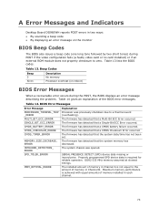
...Error Messages Error Message PROCESSOR_THERMAL_TRIP _ERROR MULTI_BIT_ECC_ERROR SINGLE_BIT_ECC_ERROR CMOS_BATTERY_ERROR CMOS_CHECKSUM_ERROR CMOS_TIMER_ERROR MEMORY_SIZE_DECREASE_ ERROR INTRUDER_DETECTION_ ERROR SPD_TOLER_ERROR MEM_OPTIMAL_ERROR Explanation Processor was opened. Table 14 gives an explanation of memory in Channel B. Properly programmed SPD device data... firmware has detected that the system date/time has not been set. A Error Messages and Indicators Desktop Board DG965WH reports POST errors in two ways: • By sounding a beep code • By displaying an error ...
...Error Messages Error Message PROCESSOR_THERMAL_TRIP _ERROR MULTI_BIT_ECC_ERROR SINGLE_BIT_ECC_ERROR CMOS_BATTERY_ERROR CMOS_CHECKSUM_ERROR CMOS_TIMER_ERROR MEMORY_SIZE_DECREASE_ ERROR INTRUDER_DETECTION_ ERROR SPD_TOLER_ERROR MEM_OPTIMAL_ERROR Explanation Processor was opened. Table 14 gives an explanation of memory in Channel B. Properly programmed SPD device data... firmware has detected that the system date/time has not been set. A Error Messages and Indicators Desktop Board DG965WH reports POST errors in two ways: • By sounding a beep code • By displaying an error ...

Product Specification
Page 5
... Manufacturing Options 11 1.1.3 Board Layout 12 1.1.4 Block Diagram 14 1.2 Online Support 15 1.3 Processor 15 1.4 System Memory 16 1.4.1 Memory Configurations 17 1.5 Intel® G965 Express Chipset 23 1.5.1 Intel G965 Graphics Subsystem 23 1.5.2 USB 25 1.5.3 Serial ATA Interfaces 26 1.5.4 Parallel IDE Interface... 28 1.7 Audio Subsystem 29 1.7.1 Audio Subsystem Software 30 1.7.2 Audio Connectors and Headers 30 1.8 LAN Subsystem 31 1.8.1 Intel® 82566DC Gigabit Ethernet Controller 31 1.8.2 LAN Subsystem Software 32 1.8.3 RJ-45 LAN Connector with Integrated LEDs 32 1.9...
... Manufacturing Options 11 1.1.3 Board Layout 12 1.1.4 Block Diagram 14 1.2 Online Support 15 1.3 Processor 15 1.4 System Memory 16 1.4.1 Memory Configurations 17 1.5 Intel® G965 Express Chipset 23 1.5.1 Intel G965 Graphics Subsystem 23 1.5.2 USB 25 1.5.3 Serial ATA Interfaces 26 1.5.4 Parallel IDE Interface... 28 1.7 Audio Subsystem 29 1.7.1 Audio Subsystem Software 30 1.7.2 Audio Connectors and Headers 30 1.8 LAN Subsystem 31 1.8.1 Intel® 82566DC Gigabit Ethernet Controller 31 1.8.2 LAN Subsystem Software 32 1.8.3 RJ-45 LAN Connector with Integrated LEDs 32 1.9...


