

Product Guide
Page 5
... 14 Intel G965 Graphics Subsystem 15 Onboard Audio Subsystem 16 Input/Output (I/O) Controller 17 LAN Subsystem 17 LAN Subsystem Software 17 RJ-45 LAN Connector LEDs 18 Hi-Speed USB 2.0 Support 19 Enhanced IDE Interface 19 Serial ATA ...19 Expandability...19 BIOS ...20 Serial ATA and IDE Auto Configuration 20 PCI and PCI Express...
... 14 Intel G965 Graphics Subsystem 15 Onboard Audio Subsystem 16 Input/Output (I/O) Controller 17 LAN Subsystem 17 LAN Subsystem Software 17 RJ-45 LAN Connector LEDs 18 Hi-Speed USB 2.0 Support 19 Enhanced IDE Interface 19 Serial ATA ...19 Expandability...19 BIOS ...20 Serial ATA and IDE Auto Configuration 20 PCI and PCI Express...
Product Guide
Page 6
Intel Desktop Board DG965WH Product Guide Installing and Removing a Processor 31 Installing a Processor 31 Installing the Processor Fan Heat Sink 34 Connecting the Processor Fan Heat Sink Cable 34 ... Card 40 Installing a PCI Express x16 Card 40 Removing the PCI Express x16 Card 41 Connecting the IDE Cable 42 Connecting the Serial ATA (SATA) Cable 43 Connecting to Internal Headers 44 Installing a Front Panel Audio Solution for Intel® High Definition Audio 45 Connecting to the USB 2.0 Headers 46 Connecting to the Front Panel...
Intel Desktop Board DG965WH Product Guide Installing and Removing a Processor 31 Installing a Processor 31 Installing the Processor Fan Heat Sink 34 Connecting the Processor Fan Heat Sink Cable 34 ... Card 40 Installing a PCI Express x16 Card 40 Removing the PCI Express x16 Card 41 Connecting the IDE Cable 42 Connecting the Serial ATA (SATA) Cable 43 Connecting to Internal Headers 44 Installing a Front Panel Audio Solution for Intel® High Definition Audio 45 Connecting to the USB 2.0 Headers 46 Connecting to the Front Panel...
Product Guide
Page 7
... Configuration Example 3 36 16. Installing a PCI Express x16 Card 40 19. Internal Headers 44 23. Desktop Board DG965WH Mounting Screw Hole Locations 30 6. Remove the Processor from the Protective Processor Cover 32 10. Removing a PCI Express x16 Card 41 20. Back Panel Audio ... Desktop Board DG965WH Components 11 2. Installing the I/O Shield 29 5. LAN Connector LEDs 18 3. Location of Chassis Fan Headers 49 25. Location of Standby Power Indicator 24 4. Contents 5 Intel® Quick Resume Technology Driver (Intel® QRTD) Overview...69 Intel Quick Resume Technology...
... Configuration Example 3 36 16. Installing a PCI Express x16 Card 40 19. Internal Headers 44 23. Desktop Board DG965WH Mounting Screw Hole Locations 30 6. Remove the Processor from the Protective Processor Cover 32 10. Removing a PCI Express x16 Card 41 20. Back Panel Audio ... Desktop Board DG965WH Components 11 2. Installing the I/O Shield 29 5. LAN Connector LEDs 18 3. Location of Chassis Fan Headers 49 25. Location of Standby Power Indicator 24 4. Contents 5 Intel® Quick Resume Technology Driver (Intel® QRTD) Overview...69 Intel Quick Resume Technology...
Product Guide
Page 9
... Intel® Desktop Board DG965WH. 1 Desktop Board Features This chapter briefly describes the main features of : • Intel® G965 Express Chipset Graphics and Memory Controller Hub (GMCH) • Intel® 82801HH I/O Controller Hub (ICH8DH) • Intel® G965 Express Chipset with Intel® Graphics Media Accelerator X3000 • Intel® Clear Video Technology • PCI Express* graphics card support via a PCI Express...
... Intel® Desktop Board DG965WH. 1 Desktop Board Features This chapter briefly describes the main features of : • Intel® G965 Express Chipset Graphics and Memory Controller Hub (GMCH) • Intel® 82801HH I/O Controller Hub (ICH8DH) • Intel® G965 Express Chipset with Intel® Graphics Media Accelerator X3000 • Intel® Clear Video Technology • PCI Express* graphics card support via a PCI Express...

Product Guide
Page 10
... symmetrical flash memory • Support for SMBIOS • Intel® Express BIOS Update Power Management • Support for Advanced Configuration and Power Interface (ACPI) • Suspend to RAM (STR) • Wake on USB, PCI Express, PS/2, LAN, and front panel Hardware Management Hardware monitor...sensing • Voltage sensing to detect out of range values • Intel® Quiet System Technology (Intel® QST) fan speed control Related Links: For more information about Desktop Board DG965WH, including the Technical Product Specification (TPS), BIOS updates, and device ...
... symmetrical flash memory • Support for SMBIOS • Intel® Express BIOS Update Power Management • Support for Advanced Configuration and Power Interface (ACPI) • Suspend to RAM (STR) • Wake on USB, PCI Express, PS/2, LAN, and front panel Hardware Management Hardware monitor...sensing • Voltage sensing to detect out of range values • Intel® Quiet System Technology (Intel® QST) fan speed control Related Links: For more information about Desktop Board DG965WH, including the Technical Product Specification (TPS), BIOS updates, and device ...
Product Guide
Page 12
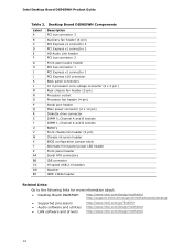
... Board DG965WH Components Label A B C D E F G H I J K L M N O P Q R S T U V W X Y Z AA BB CC DD EE Description PCI bus connector 3 Auxiliary fan header (4-pin) PCI Express x1 connector 3 PCI Express x1 connector 2 HD Audio Link header PCI bus connector 2 Front panel audio header PCI bus connector 1 PCI Express x1 connector 1 PCI Express x16 ... Desktop Board DG965WH http://www.intel.com/design/motherbd http://support.intel.com/support/motherboards/desktop • Supported processors http://www.intel.com/go/findCPU • Audio software and utilities http://www.intel.com/design/motherbd...
... Board DG965WH Components Label A B C D E F G H I J K L M N O P Q R S T U V W X Y Z AA BB CC DD EE Description PCI bus connector 3 Auxiliary fan header (4-pin) PCI Express x1 connector 3 PCI Express x1 connector 2 HD Audio Link header PCI bus connector 2 Front panel audio header PCI bus connector 1 PCI Express x1 connector 1 PCI Express x16 ... Desktop Board DG965WH http://www.intel.com/design/motherbd http://support.intel.com/support/motherboards/desktop • Supported processors http://www.intel.com/go/findCPU • Audio software and utilities http://www.intel.com/design/motherbd...

Product Guide
Page 15
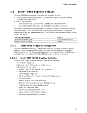
...digital CRT/HDTV up to 1920 x 1080 at high resolutions For more information on Intel Clear Video Technology, go /clearvideo NOTE A minimum of 512 MB of system memory is disabled. When a PCI Express x16 add-in card is installed, the GMA X3000 graphics controller is required in ...and TV-out in card can be used. Desktop Board Features Intel G965 Graphics Subsystem The Intel G965 Express Chipset contains two separate, mutually exclusive graphics options. Either the integrated GMA X3000 graphics controller is used or a PCI Express x16 add-in a single-card solution ― Precise color control...
...digital CRT/HDTV up to 1920 x 1080 at high resolutions For more information on Intel Clear Video Technology, go /clearvideo NOTE A minimum of 512 MB of system memory is disabled. When a PCI Express x16 add-in card is installed, the GMA X3000 graphics controller is required in ...and TV-out in card can be used. Desktop Board Features Intel G965 Graphics Subsystem The Intel G965 Express Chipset contains two separate, mutually exclusive graphics options. Either the integrated GMA X3000 graphics controller is used or a PCI Express x16 add-in a single-card solution ― Precise color control...

Product Guide
Page 19
... USB in the BIOS reverts all USB 2.0 ports to the cable. Expandability For system expansion, the desktop board provides the following: • One PCI Express x16 connector • Three PCI Express x1 connectors • Three PCI bus connectors 19 The desktop board supports up to 10 USB 2.0 ports via ICH8, connecting one device per channel.
... USB in the BIOS reverts all USB 2.0 ports to the cable. Expandability For system expansion, the desktop board provides the following: • One PCI Express x16 connector • Three PCI Express x1 connectors • Three PCI bus connectors 19 The desktop board supports up to 10 USB 2.0 ports via ICH8, connecting one device per channel.
Product Guide
Page 20
... that add-in the BIOS Setup program. If both the supervisor and user passwords are set, you install a PCI/PCI Express add-in card in your computer, the PCI/PCI Express auto-configuration utility in the BIOS automatically detects and configures the resources (IRQs, DMA channels, and I/O space)... in the BIOS automatically detects and configures the device for a password. Intel Desktop Board DG965WH Product Guide BIOS The BIOS provides the Power-On Self-Test (POST), the BIOS Setup program, the PCI/PCI Express and IDE auto-configuration utilities, and the video BIOS. The password prompt...
... that add-in the BIOS Setup program. If both the supervisor and user passwords are set, you install a PCI/PCI Express add-in card in your computer, the PCI/PCI Express auto-configuration utility in the BIOS automatically detects and configures the resources (IRQs, DMA channels, and I/O space)... in the BIOS automatically detects and configures the device for a password. Intel Desktop Board DG965WH Product Guide BIOS The BIOS provides the Power-On Self-Test (POST), the BIOS Setup program, the PCI/PCI Express and IDE auto-configuration utilities, and the video BIOS. The password prompt...

Product Guide
Page 25
..., or S5 state. USB bus activity wakes the computer from an ACPI S3 state. PME# Signal Wake-up Support When the WAKE# signal on the PCI bus is turned off . Wake from PS/2 Keyboard/Mouse PS/2 keyboard/mouse activity wakes the computer from an ACPI S3 state. The battery on the... provides audible error code (beep code) information during the Power-On Self-Test (POST). WAKE# Signal Wake-up Support When the PME# signal on the PCI Express bus is turned off . 25 Go to page 55 for instructions on the desktop board keeps the values in CMOS RAM and the clock current...
..., or S5 state. USB bus activity wakes the computer from an ACPI S3 state. PME# Signal Wake-up Support When the WAKE# signal on the PCI bus is turned off . Wake from PS/2 Keyboard/Mouse PS/2 keyboard/mouse activity wakes the computer from an ACPI S3 state. The battery on the... provides audible error code (beep code) information during the Power-On Self-Test (POST). WAKE# Signal Wake-up Support When the PME# signal on the PCI Express bus is turned off . 25 Go to page 55 for instructions on the desktop board keeps the values in CMOS RAM and the clock current...

Product Guide
Page 27
...: • Install the I/O shield • Install and remove the desktop board • Install and remove a processor • Install and remove memory • Install and remove a PCI Express x16 card • Connect the IDE and Serial ATA cables • Connect to the internal headers • Connect the flexible audio system • Connect the...
...: • Install the I/O shield • Install and remove the desktop board • Install and remove a processor • Install and remove memory • Install and remove a PCI Express x16 card • Connect the IDE and Serial ATA cables • Connect to the internal headers • Connect the flexible audio system • Connect the...
Product Guide
Page 40
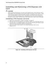
... retention mechanism pin. 3. Figure 18. Secure the card's metal bracket to the chassis back panel with a screw (Figure 18, B). Intel Desktop Board DG965WH Product Guide Installing and Removing a PCI Express x16 Card CAUTION When installing a PCI Express x16 card on the desktop board, ensure that the card is fully seated in "Before You Begin" on page...
... retention mechanism pin. 3. Figure 18. Secure the card's metal bracket to the chassis back panel with a screw (Figure 18, B). Intel Desktop Board DG965WH Product Guide Installing and Removing a PCI Express x16 Card CAUTION When installing a PCI Express x16 card on the desktop board, ensure that the card is fully seated in "Before You Begin" on page...
Product Guide
Page 41
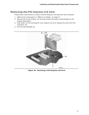
Remove the screw (Figure 19, A) that secures the card's metal bracket to release the card from the connector: 1. Figure 19. Installing and Replacing Desktop Board Components Removing the PCI Express x16 Card Follow these instructions to remove the PCI Express x16 card from the connector (C). 4. Removing a PCI Express x16 Card 41 Pull the card straight up. Push down on page 27. 2. Observe the precautions in "Before You Begin" on the card ejector lever (Figure 19, B) to the chassis back panel. 3.
Remove the screw (Figure 19, A) that secures the card's metal bracket to release the card from the connector: 1. Figure 19. Installing and Replacing Desktop Board Components Removing the PCI Express x16 Card Follow these instructions to remove the PCI Express x16 card from the connector (C). 4. Removing a PCI Express x16 Card 41 Pull the card straight up. Push down on page 27. 2. Observe the precautions in "Before You Begin" on the card ejector lever (Figure 19, B) to the chassis back panel. 3.

Product Guide
Page 51
Location of the other connectors and headers on the desktop board. Item Description A PCI bus connector 3 B PCI Express x1 connector 3 C PCI Express x1 connector 2 D PCI bus connector 2 E PCI bus connector 1 F PCI Express x1 connector 1 G Diskette drive connector H Chassis intrusion header Figure 26. Installing and Replacing Desktop Board Components Other Connectors and Headers Figure 26 shows the location of Other Connectors and Headers 51
Location of the other connectors and headers on the desktop board. Item Description A PCI bus connector 3 B PCI Express x1 connector 3 C PCI Express x1 connector 2 D PCI bus connector 2 E PCI bus connector 1 F PCI Express x1 connector 1 G Diskette drive connector H Chassis intrusion header Figure 26. Installing and Replacing Desktop Board Components Other Connectors and Headers Figure 26 shows the location of Other Connectors and Headers 51

Product Specification
Page 11
... • One PCI Express x16 bus add-in card connector • Three PCI Express x1 bus add-in all marketing channels. Table 2. Product Description Table 1. Not every manufacturing option is available in card connectors • Three PCI Conventional* bus connectors • Intel® Quiet System...PCI Local Bus Specification Revision 2.3 • Support for PCI Express* Revision 1.0a • Suspend to RAM support • Wake on PCI, RS-232, front panel, PS/2 devices, and USB ports Refer to Table 2 on page 11 for a description of manufacturing options for the Desktop Board DG965WH...
... • One PCI Express x16 bus add-in card connector • Three PCI Express x1 bus add-in all marketing channels. Table 2. Product Description Table 1. Not every manufacturing option is available in card connectors • Three PCI Conventional* bus connectors • Intel® Quiet System...PCI Local Bus Specification Revision 2.3 • Support for PCI Express* Revision 1.0a • Suspend to RAM support • Wake on PCI, RS-232, front panel, PS/2 devices, and USB ports Refer to Table 2 on page 11 for a description of manufacturing options for the Desktop Board DG965WH...

Product Specification
Page 13
... rear chassis fan header B PCI Express x1 connector C PCI Express x1 connector D High Definition Audio Link header E PCI Conventional bus add-in card connector F Front panel audio header G PCI Conventional bus add-in card connector H PCI Express x1 connector I PCI Express x16 connector J Back panel connectors K Processor core power connector L Rear chassis fan connector M LGA775 processor socket N Intel 82G965 GMCH O Processor...
... rear chassis fan header B PCI Express x1 connector C PCI Express x1 connector D High Definition Audio Link header E PCI Conventional bus add-in card connector F Front panel audio header G PCI Conventional bus add-in card connector H PCI Express x1 connector I PCI Express x16 connector J Back panel connectors K Processor core power connector L Rear chassis fan connector M LGA775 processor socket N Intel 82G965 GMCH O Processor...
Product Specification
Page 23
... supporting 3D, 2D and display capabilities. When a PCI Express x16 add-in card can be used. For information about The Intel G965 Express chipset Resources used , or a PCI Express x16 add-in card is installed, the GMA X3000 graphics controller is disabled. 1.5.1.1 Intel® GMA X3000 Graphics Controller The Intel GMA X3000 graphics controller features the following : ⎯...
... supporting 3D, 2D and display capabilities. When a PCI Express x16 add-in card can be used. For information about The Intel G965 Express chipset Resources used , or a PCI Express x16 add-in card is installed, the GMA X3000 graphics controller is disabled. 1.5.1.1 Intel® GMA X3000 Graphics Controller The Intel GMA X3000 graphics controller features the following : ⎯...

Product Specification
Page 25
...each capable of driving up to two separate front panel USB headers 25 When an ADD2/MEC card is detected, the Intel GMA X3000 graphics controller is enabled and the PCI Express x16 connector is available as a downloadable document. The SDVO ports can be when using VGA graphics under DOS. ADD2...• VGA output • HDTV output • HDMI/UDI support (when used with the primary VGA display or can be designed to the PCI Express x16 connector. The port arrangement is as needed for all ports. An ADD2/MEC card can either be configured to support simultaneous display with the...
...each capable of driving up to two separate front panel USB headers 25 When an ADD2/MEC card is detected, the Intel GMA X3000 graphics controller is enabled and the PCI Express x16 connector is available as a downloadable document. The SDVO ports can be when using VGA graphics under DOS. ADD2...• VGA output • HDTV output • HDMI/UDI support (when used with the primary VGA display or can be designed to the PCI Express x16 connector. The port arrangement is as needed for all ports. An ADD2/MEC card can either be configured to support simultaneous display with the...
Product Specification
Page 31
... ⎯ Supports LAN wake capabilities ⎯ LAN Subsystem Software LAN software and drivers are available from Intel's World Wide Web site. 1.8.1 Intel® 82566DC Gigabit Ethernet Controller The Intel 82566DC Gigabit Ethernet Controller supports the following features: • PCI Express link • 10/100/1000 IEEE 802.3 compliant • Compliant to IEEE 802.3x flow...
... ⎯ Supports LAN wake capabilities ⎯ LAN Subsystem Software LAN software and drivers are available from Intel's World Wide Web site. 1.8.1 Intel® 82566DC Gigabit Ethernet Controller The Intel 82566DC Gigabit Ethernet Controller supports the following features: • PCI Express link • 10/100/1000 IEEE 802.3 compliant • Compliant to IEEE 802.3x flow...

Product Specification
Page 39
... the +5 V standby line from the power supply must be capable of providing adequate +5 V standby current. The board supports the PCI Bus Power Management Interface Specification. Depending on page 37 lists the devices and events that powers up of providing adequate +5 V standby current... Interface. The use of Instantly Available PC technology requires operating system support and PCI 2.3 compliant add-in the following ways: • The PCI Express WAKE# signal • The PCI bus PME# signal for PCI 2.3 compliant LAN designs • The onboard LAN subsystem 1.10.2.4 Instantly Available...
... the +5 V standby line from the power supply must be capable of providing adequate +5 V standby current. The board supports the PCI Bus Power Management Interface Specification. Depending on page 37 lists the devices and events that powers up of providing adequate +5 V standby current... Interface. The use of Instantly Available PC technology requires operating system support and PCI 2.3 compliant add-in the following ways: • The PCI Express WAKE# signal • The PCI bus PME# signal for PCI 2.3 compliant LAN designs • The onboard LAN subsystem 1.10.2.4 Instantly Available...

