

Product Guide
Page 4
... cable • Two locking Serial ATA cables • Back panel audio port covers • Intel® Express Installer DVD-ROM • Intel® Matrix Storage Technology RAID driver diskette • Quick Reference poster • Configuration and battery caution statement label iv Intel Desktop Board DG965WH Product Guide Terminology The table below gives descriptions of some...
... cable • Two locking Serial ATA cables • Back panel audio port covers • Intel® Express Installer DVD-ROM • Intel® Matrix Storage Technology RAID driver diskette • Quick Reference poster • Configuration and battery caution statement label iv Intel Desktop Board DG965WH Product Guide Terminology The table below gives descriptions of some...
Product Guide
Page 6
Intel Desktop Board DG965WH Product Guide Installing and Removing a Processor 31 Installing a Processor 31 Installing the Processor Fan Heat Sink 34 Connecting the Processor Fan Heat Sink Cable 34 ... 49 Connecting Power Cables 50 Other Connectors and Headers 51 Setting the BIOS Configuration Jumper 52 Clearing Passwords 53 Back Panel Connectors 54 3 Updating the BIOS Updating the BIOS with the Intel® Express BIOS Update Utility 61 Updating the BIOS with the ISO Image BIOS Update File or the Iflash Memory...
Intel Desktop Board DG965WH Product Guide Installing and Removing a Processor 31 Installing a Processor 31 Installing the Processor Fan Heat Sink 34 Connecting the Processor Fan Heat Sink Cable 34 ... 49 Connecting Power Cables 50 Other Connectors and Headers 51 Setting the BIOS Configuration Jumper 52 Clearing Passwords 53 Back Panel Connectors 54 3 Updating the BIOS Updating the BIOS with the Intel® Express BIOS Update Utility 61 Updating the BIOS with the ISO Image BIOS Update File or the Iflash Memory...
Product Guide
Page 7
...Serial ATA Cable 43 22. Desktop Board DG965WH Components 11 2. LAN Connector LEDs 18 3. Close the Load Plate 33 12. Connecting Power Supply Cables 50 26. Contents 5 Intel® Quick Resume Technology Driver (Intel® QRTD) Overview...69 Intel Quick Resume Technology Power Modes 69 Installation and...32 9. Install the Processor 33 11. Installing a PCI Express x16 Card 40 19. Internal Headers 44 23. Back Panel Audio Connectors 48 24. Back Panel Connectors 54 29. Installing the I/O Shield 29 5. Connecting the Processor Fan Heat Sink Cable to the Processor Fan ...
...Serial ATA Cable 43 22. Desktop Board DG965WH Components 11 2. LAN Connector LEDs 18 3. Close the Load Plate 33 12. Connecting Power Supply Cables 50 26. Contents 5 Intel® Quick Resume Technology Driver (Intel® QRTD) Overview...69 Intel Quick Resume Technology Power Modes 69 Installation and...32 9. Install the Processor 33 11. Installing a PCI Express x16 Card 40 19. Internal Headers 44 23. Back Panel Audio Connectors 48 24. Back Panel Connectors 54 29. Installing the I/O Shield 29 5. Connecting the Processor Fan Heat Sink Cable to the Processor Fan ...
Product Guide
Page 8
... Signal Names 46 7. Alternate Front Panel Power LED Header 47 9. Jumper Settings for Desktop Board DG965WH After RAID is Enabled 66 Tables 1. Safety Regulations 75 16. Lead-Free Board Markings 80 17. AC '97 Audio Header Signal Names 45 6. Front Panel Header 46 8. HD Audio Link... Names 47 11. Feature Summary 9 2. Front Panel Audio Header Signal Names for Desktop Board DG965WH 65 31. BIOS Error Messages 73 15. IEEE 1394a Header Signal Names 47 10. Product Certification Markings 83 viii Intel Desktop Board DG965WH Product Guide 30. LAN Connector LED States 18 ...
... Signal Names 46 7. Alternate Front Panel Power LED Header 47 9. Jumper Settings for Desktop Board DG965WH After RAID is Enabled 66 Tables 1. Safety Regulations 75 16. Lead-Free Board Markings 80 17. AC '97 Audio Header Signal Names 45 6. Front Panel Header 46 8. HD Audio Link... Names 47 11. Feature Summary 9 2. Front Panel Audio Header Signal Names for Desktop Board DG965WH 65 31. BIOS Error Messages 73 15. IEEE 1394a Header Signal Names 47 10. Product Certification Markings 83 viii Intel Desktop Board DG965WH Product Guide 30. LAN Connector LED States 18 ...
Product Guide
Page 9
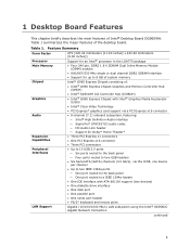
... IEEE 1394a ports ― One port routed to the back panel ― One port routed to 8 GB of system memory Intel® G965 Express Chipset consisting of Intel® Desktop Board DG965WH. 1 Desktop Board Features This chapter briefly describes the main features of : • Intel® G965 Express Chipset Graphics and Memory Controller Hub (GMCH...
... IEEE 1394a ports ― One port routed to the back panel ― One port routed to 8 GB of system memory Intel® G965 Express Chipset consisting of Intel® Desktop Board DG965WH. 1 Desktop Board Features This chapter briefly describes the main features of : • Intel® G965 Express Chipset Graphics and Memory Controller Hub (GMCH...

Product Guide
Page 10
..., and front panel Hardware Management Hardware monitor with: • Three fan sensing inputs used to monitor fan activity • Remote diode temperature sensing • Voltage sensing to detect out of range values • Intel® Quiet System Technology (Intel® QST) fan speed control Related Links: For more information about Desktop Board DG965WH, including...
..., and front panel Hardware Management Hardware monitor with: • Three fan sensing inputs used to monitor fan activity • Remote diode temperature sensing • Voltage sensing to detect out of range values • Intel® Quiet System Technology (Intel® QST) fan speed control Related Links: For more information about Desktop Board DG965WH, including...
Product Guide
Page 12
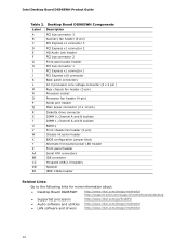
... BIOS configuration jumper block Alternate front panel power LED header Front panel header Serial ATA connectors IDE connector Hi-speed USB 2.0 headers Speaker IEEE 1394a header Related Links: Go to the following links for more information about: • Desktop Board DG965WH http://www.intel.com/design/motherbd http://support.intel.com/support/motherboards/desktop •...
... BIOS configuration jumper block Alternate front panel power LED header Front panel header Serial ATA connectors IDE connector Hi-speed USB 2.0 headers Speaker IEEE 1394a header Related Links: Go to the following links for more information about: • Desktop Board DG965WH http://www.intel.com/design/motherbd http://support.intel.com/support/motherboards/desktop •...

Product Guide
Page 15
... core frequency • Enhanced 3D graphics • Flat panel displays up to 2048 x 1536 at 75 Hz refresh rate (in dual-channel mode) or digital CRT/HDTV up to 1920 x 1080 at 85 Hz refresh rate • Dynamic Video Memory Technology (DVMT). • Intel Clear Video Technology which supports: ― Enhanced high...
... core frequency • Enhanced 3D graphics • Flat panel displays up to 2048 x 1536 at 75 Hz refresh rate (in dual-channel mode) or digital CRT/HDTV up to 1920 x 1080 at 85 Hz refresh rate • Dynamic Video Memory Technology (DVMT). • Intel Clear Video Technology which supports: ― Enhanced high...

Product Guide
Page 16
...: ― Line out ― Microphone in • Back panel audio connectors that includes a SigmaTel STAC9271D audio codec and an HD Audio Link header. Intel Desktop Board DG965WH Product Guide Onboard Audio Subsystem Desktop Board DG965WH has a flexible 8-channel (7.1) onboard audio subsystem that are configurable ...the following link or pages for more information about: • Audio drivers and utilities http://support.intel.com/support/motherboards/desktop/ • Installing the front panel audio solution, page 45 • The location of audio connectors, Figure 23 on page 48 16
...: ― Line out ― Microphone in • Back panel audio connectors that includes a SigmaTel STAC9271D audio codec and an HD Audio Link header. Intel Desktop Board DG965WH Product Guide Onboard Audio Subsystem Desktop Board DG965WH has a flexible 8-channel (7.1) onboard audio subsystem that are configurable ...the following link or pages for more information about: • Audio drivers and utilities http://support.intel.com/support/motherboards/desktop/ • Installing the front panel audio solution, page 45 • The location of audio connectors, Figure 23 on page 48 16

Product Guide
Page 18
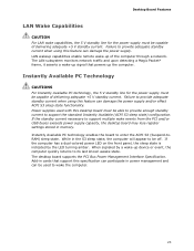
... Green N/A Green Yellow LED State Off On Blinking Off On On Indicates LAN link is not established LAN link is established LAN activity is operating. Intel Desktop Board DG965WH Product Guide RJ-45 LAN Connector LEDs Two LEDs are built into the RJ-45 LAN connector located on the back...
... Green N/A Green Yellow LED State Off On Blinking Off On On Indicates LAN link is not established LAN link is established LAN activity is operating. Intel Desktop Board DG965WH Product Guide RJ-45 LAN Connector LEDs Two LEDs are built into the RJ-45 LAN connector located on the back...

Product Guide
Page 19
...-33 and ATA-66/100 protocols Serial ATA The desktop board supports six Serial ATA channels (3.0 Gb/s) via ICH8 (six ports routed to the back panel and four ports routed to 10 USB 2.0 ports via ICH8, connecting one device per channel. This may be required to accommodate operating systems that have...
...-33 and ATA-66/100 protocols Serial ATA The desktop board supports six Serial ATA channels (3.0 Gb/s) via ICH8 (six ports routed to the back panel and four ports routed to 10 USB 2.0 ports via ICH8, connecting one device per channel. This may be required to accommodate operating systems that have...
Product Guide
Page 23
... asserts a wake-up the computer. Power supplies used to its last known awake state. If the computer has a dual-colored power LED on the front panel, the sleep state is indicated by a wake-up of the computer through a network. Failure to provide adequate standby current when using this specification can participate...
... asserts a wake-up the computer. Power supplies used to its last known awake state. If the computer has a dual-colored power LED on the front panel, the sleep state is indicated by a wake-up of the computer through a network. Failure to provide adequate standby current when using this specification can participate...

Product Guide
Page 27
... before you begin: • Always follow the steps in each procedure in the correct order. • Set up a log to operate even though the front panel power button is not available, you can damage components. Follow these guidelines before you open the computer or perform any of the computer chassis. 27...
... before you begin: • Always follow the steps in each procedure in the correct order. • Set up a log to operate even though the front panel power button is not available, you can damage components. Follow these guidelines before you open the computer or perform any of the computer chassis. 27...
Product Guide
Page 40
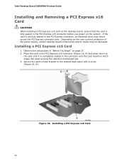
... and the card retention notch snaps into place around the retention mechanism pin. 3. Figure 18. Secure the card's metal bracket to the chassis back panel with a screw (Figure 18, B). Installing a PCI Express x16 Card 1. Place the card in the PCI Express x16 connector (Figure 18, A)...the PCI Express connector pins. Installing a PCI Express x16 Card 40 Observe the precautions in "Before You Begin" on the system. Intel Desktop Board DG965WH Product Guide Installing and Removing a PCI Express x16 Card CAUTION When installing a PCI Express x16 card on the desktop board, ensure that...
... and the card retention notch snaps into place around the retention mechanism pin. 3. Figure 18. Secure the card's metal bracket to the chassis back panel with a screw (Figure 18, B). Installing a PCI Express x16 Card 1. Place the card in the PCI Express x16 connector (Figure 18, A)...the PCI Express connector pins. Installing a PCI Express x16 Card 40 Observe the precautions in "Before You Begin" on the system. Intel Desktop Board DG965WH Product Guide Installing and Removing a PCI Express x16 Card CAUTION When installing a PCI Express x16 card on the desktop board, ensure that...
Product Guide
Page 41
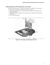
Push down on page 27. 2. Pull the card straight up. Installing and Replacing Desktop Board Components Removing the PCI Express x16 Card Follow these instructions to release the card from the connector: 1. Removing a PCI Express x16 Card 41 Remove the screw (Figure 19, A) that secures the card's metal bracket to the chassis back panel. 3. Figure 19. Observe the precautions in "Before You Begin" on the card ejector lever (Figure 19, B) to remove the PCI Express x16 card from the connector (C). 4.
Push down on page 27. 2. Pull the card straight up. Installing and Replacing Desktop Board Components Removing the PCI Express x16 Card Follow these instructions to release the card from the connector: 1. Removing a PCI Express x16 Card 41 Remove the screw (Figure 19, A) that secures the card's metal bracket to the chassis back panel. 3. Figure 19. Observe the precautions in "Before You Begin" on the card ejector lever (Figure 19, B) to remove the PCI Express x16 card from the connector (C). 4.

Product Guide
Page 44
Intel Desktop Board DG965WH Product Guide Connecting to Internal Headers Before connecting cables to the internal headers, observe the precautions in "Before You Begin" on page 27. Internal Headers 44 Item Description A HD Audio Link B IEEE 1394a C Front panel audio D Serial port E Front panel F Alternate front panel power LED G USB 2.0 Figure 22. Figure 22 shows the location of the internal headers.
Intel Desktop Board DG965WH Product Guide Connecting to Internal Headers Before connecting cables to the internal headers, observe the precautions in "Before You Begin" on page 27. Internal Headers 44 Item Description A HD Audio Link B IEEE 1394a C Front panel audio D Serial port E Front panel F Alternate front panel power LED G USB 2.0 Figure 22. Figure 22 shows the location of the internal headers.

Product Guide
Page 45
... cable. Turn off the computer and disconnect the AC power cord. 3. Remove the cover. 4. Table 4. Installing and Replacing Desktop Board Components Installing a Front Panel Audio Solution for Intel High Definition Audio Pin Signal Name 1 PORT 1L Pin Signal Name 2 GND 3 PORT 1R 4 PRESENCE# 5 PORT 2R 7 SENSE_SEND 9 PORT 2L 6 SENSE1_RETURN 8 KEY (no pin...
... cable. Turn off the computer and disconnect the AC power cord. 3. Remove the cover. 4. Table 4. Installing and Replacing Desktop Board Components Installing a Front Panel Audio Solution for Intel High Definition Audio Pin Signal Name 1 PORT 1L Pin Signal Name 2 GND 3 PORT 1R 4 PRESENCE# 5 PORT 2R 7 SENSE_SEND 9 PORT 2L 6 SENSE1_RETURN 8 KEY (no pin...

Product Guide
Page 46
... 6 7 GND 8 9 KEY 10 Note: USB ports may be assigned as needed. Table 7 shows the pin assignments for the location of the multi-colored front panel header. Remove the cover. 4. See Figure 22, G on page 27. 2. See Figure 22, E on page 27. Table 7. Turn off the computer and disconnect... 6 shows the pin assignments for the location of the black USB 2.0 headers. Front Panel Header Pin Description Hard Drive Activity LED 1 Hard disk LED pull-up to the computer. Intel Desktop Board DG965WH Product Guide To restore back panel audio, follow these steps: 1. Replace the cover.
... 6 7 GND 8 9 KEY 10 Note: USB ports may be assigned as needed. Table 7 shows the pin assignments for the location of the multi-colored front panel header. Remove the cover. 4. See Figure 22, G on page 27. 2. See Figure 22, E on page 27. Table 7. Turn off the computer and disconnect... 6 shows the pin assignments for the location of the black USB 2.0 headers. Front Panel Header Pin Description Hard Drive Activity LED 1 Hard disk LED pull-up to the computer. Intel Desktop Board DG965WH Product Guide To restore back panel audio, follow these steps: 1. Replace the cover.

Product Guide
Page 47
... LED In/Out Out Out Connecting to the IEEE 1394a Header See Figure 22, B for the front panel header. Table 9. Table 10. Serial Port Header Signal Names Pin Signal Name 1 DCD Pin Signal Name 2 RXD# 3 TXD# 5 Ground 7 RTS 4 DTR 6 DSR 8 CTS 9 RI 10 ... your chassis has a three-pin power LED cable, connect it to this header duplicate the signals on page 44 shows the location of the front panel header. Installing and Replacing Desktop Board Components Connecting to the Alternate Front Panel Power LED Header Figure 22, F on pins 2 and 4 of the alternate front...
... LED In/Out Out Out Connecting to the IEEE 1394a Header See Figure 22, B for the front panel header. Table 9. Table 10. Serial Port Header Signal Names Pin Signal Name 1 DCD Pin Signal Name 2 RXD# 3 TXD# 5 Ground 7 RTS 4 DTR 6 DSR 8 CTS 9 RI 10 ... your chassis has a three-pin power LED cable, connect it to this header duplicate the signals on page 44 shows the location of the front panel header. Installing and Replacing Desktop Board Components Connecting to the Alternate Front Panel Power LED Header Figure 22, F on pins 2 and 4 of the alternate front...

Product Guide
Page 48
... in/side surround left and right/retasking jack D Line out/retasking jack E Mic in the table. Figure 23 shows the back panel audio connectors. Back Panel Audio Connectors 48 Intel Desktop Board DG965WH Product Guide Connecting to the Flexible Audio System After installing the SigmaTel audio driver, the multi-channel audio feature can be...
... in/side surround left and right/retasking jack D Line out/retasking jack E Mic in the table. Figure 23 shows the back panel audio connectors. Back Panel Audio Connectors 48 Intel Desktop Board DG965WH Product Guide Connecting to the Flexible Audio System After installing the SigmaTel audio driver, the multi-channel audio feature can be...


