

Product Guide
Page 4
...(1024 bytes) MB Megabyte (1,048,576 bytes) Mbit Megabit (1,048,576 bits) MHz Megahertz (one million hertz) Box Contents • Intel Desktop Board DG965WH • I/O shield • One diskette drive cable • One ATA-66/100 cable • Two locking Serial ATA cables •... Back panel audio port covers • Intel® Express Installer DVD-ROM • Intel® Matrix Storage Technology RAID driver diskette • Quick Reference ...
...(1024 bytes) MB Megabyte (1,048,576 bytes) Mbit Megabit (1,048,576 bits) MHz Megahertz (one million hertz) Box Contents • Intel Desktop Board DG965WH • I/O shield • One diskette drive cable • One ATA-66/100 cable • Two locking Serial ATA cables •... Back panel audio port covers • Intel® Express Installer DVD-ROM • Intel® Matrix Storage Technology RAID driver diskette • Quick Reference ...

Product Guide
Page 5
Contents 1 Desktop Board Features Supported Operating Systems 10 Desktop Board Components 11 Processor ...13 Main Memory ...13 Intel® G965 Express Chipset 14 Intel G965 Graphics Subsystem 15 Onboard Audio Subsystem 16 Input/Output (I/O) Controller 17 LAN Subsystem 17 LAN Subsystem Software 17 RJ-45 LAN Connector LEDs 18 Hi-Speed USB 2.0 Support 19...
Contents 1 Desktop Board Features Supported Operating Systems 10 Desktop Board Components 11 Processor ...13 Main Memory ...13 Intel® G965 Express Chipset 14 Intel G965 Graphics Subsystem 15 Onboard Audio Subsystem 16 Input/Output (I/O) Controller 17 LAN Subsystem 17 LAN Subsystem Software 17 RJ-45 LAN Connector LEDs 18 Hi-Speed USB 2.0 Support 19...
Product Guide
Page 6
Intel Desktop Board DG965WH Product Guide Installing and Removing a Processor 31 Installing a Processor 31 Installing ... Connecting the Serial ATA (SATA) Cable 43 Connecting to Internal Headers 44 Installing a Front Panel Audio Solution for Intel® High Definition Audio 45 Connecting to the USB 2.0 Headers 46 Connecting to the Front Panel Header 46 Connecting to... 1394a Header 47 Connecting to the Serial Port Header 47 Connecting to the HD Audio Link Header 48 Connecting to the Flexible Audio System 48 Connecting Chassis Fan and Power Cables 49 Connecting Chassis Fan Cables 49 ...
Intel Desktop Board DG965WH Product Guide Installing and Removing a Processor 31 Installing a Processor 31 Installing ... Connecting the Serial ATA (SATA) Cable 43 Connecting to Internal Headers 44 Installing a Front Panel Audio Solution for Intel® High Definition Audio 45 Connecting to the USB 2.0 Headers 46 Connecting to the Front Panel Header 46 Connecting to... 1394a Header 47 Connecting to the Serial Port Header 47 Connecting to the HD Audio Link Header 48 Connecting to the Flexible Audio System 48 Connecting Chassis Fan and Power Cables 49 Connecting Chassis Fan Cables 49 ...
Product Guide
Page 7
... 29 5. Dual Channel Memory Configuration Example 3 36 16. Removing a PCI Express x16 Card 41 20. Back Panel Audio Connectors 48 24. Desktop Board DG965WH Mounting Screw Hole Locations 30 6. Connecting the Processor Fan Heat Sink Cable to the Processor Fan Header.......... 34 13. ... the Protective Processor Cover 32 10. Dual Channel Memory Configuration Example 1 35 14. Contents 5 Intel® Quick Resume Technology Driver (Intel® QRTD) Overview...69 Intel Quick Resume Technology Power Modes 69 Installation and Configuration 70 A Error Messages and Indicators BIOS Beep Codes...
... 29 5. Dual Channel Memory Configuration Example 3 36 16. Removing a PCI Express x16 Card 41 20. Back Panel Audio Connectors 48 24. Desktop Board DG965WH Mounting Screw Hole Locations 30 6. Connecting the Processor Fan Heat Sink Cable to the Processor Fan Header.......... 34 13. ... the Protective Processor Cover 32 10. Dual Channel Memory Configuration Example 1 35 14. Contents 5 Intel® Quick Resume Technology Driver (Intel® QRTD) Overview...69 Intel Quick Resume Technology Power Modes 69 Installation and Configuration 70 A Error Messages and Indicators BIOS Beep Codes...
Product Guide
Page 8
...Header Signal Names 46 7. Serial Port Header Signal Names 47 11. Intel Desktop Board DG965WH Product Guide 30. IEEE 1394a Header Signal Names 47 10. Front Panel Audio Header Signal Names for Desktop Board DG965WH After RAID is Enabled 66 Tables 1. Front Panel Header 46 8. Beep... 15. Lead-Free Board Markings 80 17. SATA Port Mapping for Intel High Definition Audio 45 5. Product Certification Markings 83 viii Desktop Board DG965WH Components 12 3. Jumper Settings for Desktop Board DG965WH 65 31. Original SATA Port Mapping for the BIOS Setup Program Modes...
...Header Signal Names 46 7. Serial Port Header Signal Names 47 11. Intel Desktop Board DG965WH Product Guide 30. IEEE 1394a Header Signal Names 47 10. Front Panel Audio Header Signal Names for Desktop Board DG965WH After RAID is Enabled 66 Tables 1. Front Panel Header 46 8. Beep... 15. Lead-Free Board Markings 80 17. SATA Port Mapping for Intel High Definition Audio 45 5. Product Certification Markings 83 viii Desktop Board DG965WH Components 12 3. Jumper Settings for Desktop Board DG965WH 65 31. Original SATA Port Mapping for the BIOS Setup Program Modes...
Product Guide
Page 9
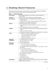
... Express* graphics card support via a PCI Express x16 connector • 8-channel (7.1) onboard subsystem, featuring: ― Intel® High Definition Audio interface ― SigmaTel* STAC9271D audio codec ― HD Audio Link header ― Support for Dolby* Home Theater* • Three PCI Express x1 connectors • One PCI .../533 MHz single or dual channel DDR2 SDRAM interface • Support for up to 8 GB of system memory Intel® G965 Express Chipset consisting of Intel® Desktop Board DG965WH. Table 1 summarizes the major features of the desktop board. Table 1.
... Express* graphics card support via a PCI Express x16 connector • 8-channel (7.1) onboard subsystem, featuring: ― Intel® High Definition Audio interface ― SigmaTel* STAC9271D audio codec ― HD Audio Link header ― Support for Dolby* Home Theater* • Three PCI Express x1 connectors • One PCI .../533 MHz single or dual channel DDR2 SDRAM interface • Support for up to 8 GB of system memory Intel® G965 Express Chipset consisting of Intel® Desktop Board DG965WH. Table 1 summarizes the major features of the desktop board. Table 1.
Product Guide
Page 12
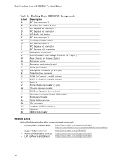
... header Related Links: Go to the following links for more information about: • Desktop Board DG965WH http://www.intel.com/design/motherbd http://support.intel.com/support/motherboards/desktop • Supported processors http://www.intel.com/go/findCPU • Audio software and utilities http://www.intel.com/design/motherbd • LAN software and drivers http://www...
... header Related Links: Go to the following links for more information about: • Desktop Board DG965WH http://www.intel.com/design/motherbd http://support.intel.com/support/motherboards/desktop • Supported processors http://www.intel.com/go/findCPU • Audio software and utilities http://www.intel.com/design/motherbd • LAN software and drivers http://www...

Product Guide
Page 16
Intel Desktop Board DG965WH Product Guide Onboard Audio Subsystem Desktop Board DG965WH has a flexible 8-channel (7.1) onboard audio subsystem that are configurable through the audio device drivers: ― Surround left and right/retasking jack ― Center channel and LFE (subwoofer)/retasking jack ― S/PDIF optical digital audio... jack ― Mic in • Back panel audio connectors that includes a SigmaTel STAC9271D audio codec and an HD Audio Link header. The audio subsystem features: • Intel® High Definition Audio interface • Advanced jack sense, for the back...
Intel Desktop Board DG965WH Product Guide Onboard Audio Subsystem Desktop Board DG965WH has a flexible 8-channel (7.1) onboard audio subsystem that are configurable through the audio device drivers: ― Surround left and right/retasking jack ― Center channel and LFE (subwoofer)/retasking jack ― S/PDIF optical digital audio... jack ― Mic in • Back panel audio connectors that includes a SigmaTel STAC9271D audio codec and an HD Audio Link header. The audio subsystem features: • Intel® High Definition Audio interface • Advanced jack sense, for the back...

Product Guide
Page 27
...; Install and remove a PCI Express x16 card • Connect the IDE and Serial ATA cables • Connect to the internal headers • Connect the flexible audio system • Connect the chassis fan and power cables • Set the BIOS configuration jumper • Clear passwords • Replace the battery Before You Begin...
...; Install and remove a PCI Express x16 card • Connect the IDE and Serial ATA cables • Connect to the internal headers • Connect the flexible audio system • Connect the chassis fan and power cables • Set the BIOS configuration jumper • Clear passwords • Replace the battery Before You Begin...

Product Guide
Page 44
Figure 22 shows the location of the internal headers. Item Description A HD Audio Link B IEEE 1394a C Front panel audio D Serial port E Front panel F Alternate front panel power LED G USB 2.0 Figure 22. Internal Headers 44 Intel Desktop Board DG965WH Product Guide Connecting to Internal Headers Before connecting cables to the internal headers, observe the precautions in "Before You Begin" on page 27.
Figure 22 shows the location of the internal headers. Item Description A HD Audio Link B IEEE 1394a C Front panel audio D Serial port E Front panel F Alternate front panel power LED G USB 2.0 Figure 22. Internal Headers 44 Intel Desktop Board DG965WH Product Guide Connecting to Internal Headers Before connecting cables to the internal headers, observe the precautions in "Before You Begin" on page 27.

Product Guide
Page 45
...AC '97 front panel solution to the front panel audio solution. 6. Front Panel Audio Header Signal Names for Intel® High Definition Audio Figure 22, C on the board. Connect the audio cable to the front panel audio header on page 44 shows the location of the ...KEY 10 FP_RETURN_L 5. Turn off the computer and disconnect the AC power cord. 3. Installing and Replacing Desktop Board Components Installing a Front Panel Audio Solution for Intel High Definition Audio Pin Signal Name 1 PORT 1L Pin Signal Name 2 GND 3 PORT 1R 4 PRESENCE# 5 PORT 2R 7 SENSE_SEND 9 PORT 2L ...
...AC '97 front panel solution to the front panel audio solution. 6. Front Panel Audio Header Signal Names for Intel® High Definition Audio Figure 22, C on the board. Connect the audio cable to the front panel audio header on page 44 shows the location of the ...KEY 10 FP_RETURN_L 5. Turn off the computer and disconnect the AC power cord. 3. Installing and Replacing Desktop Board Components Installing a Front Panel Audio Solution for Intel High Definition Audio Pin Signal Name 1 PORT 1L Pin Signal Name 2 GND 3 PORT 1R 4 PRESENCE# 5 PORT 2R 7 SENSE_SEND 9 PORT 2L ...

Product Guide
Page 46
... disk LED pull-up to the USB 2.0 headers, observe the precautions in "Before You Begin" on page 27. Intel Desktop Board DG965WH Product Guide To restore back panel audio, follow these steps: 1. Remove the front panel audio cable. 5. Table 6. Table 7 shows the pin assignments for each USB 2.0 header. Table 7. Observe the precautions in "Before...
... disk LED pull-up to the USB 2.0 headers, observe the precautions in "Before You Begin" on page 27. Intel Desktop Board DG965WH Product Guide To restore back panel audio, follow these steps: 1. Remove the front panel audio cable. 5. Table 6. Table 7 shows the pin assignments for each USB 2.0 header. Table 7. Observe the precautions in "Before...

Product Guide
Page 48
.../retasking jack E Mic in the table. Table 9 shows the pin assignments for the location of the HD Audio Link header. Intel Desktop Board DG965WH Product Guide Connecting to the Flexible Audio System After installing the SigmaTel audio driver, the multi-channel audio feature can be enabled. The connectors are shown in /retasking jack F S/PDIF optical digital...
.../retasking jack E Mic in the table. Table 9 shows the pin assignments for the location of the HD Audio Link header. Intel Desktop Board DG965WH Product Guide Connecting to the Flexible Audio System After installing the SigmaTel audio driver, the multi-channel audio feature can be enabled. The connectors are shown in /retasking jack F S/PDIF optical digital...

Product Guide
Page 54
Figure 28 shows the back panel connectors. Back Panel Connectors 54 Intel Desktop Board DG965WH Product Guide Back Panel Connectors NOTE The line out connector, located on the back panel, is designed to this output. Figure 28. Poor audio quality may occur if passive (non-amplified) speakers are connected to power either headphones or amplified speakers only.
Figure 28 shows the back panel connectors. Back Panel Connectors 54 Intel Desktop Board DG965WH Product Guide Back Panel Connectors NOTE The line out connector, located on the back panel, is designed to this output. Figure 28. Poor audio quality may occur if passive (non-amplified) speakers are connected to power either headphones or amplified speakers only.

Product Guide
Page 69
...Mode option: • In Quick Resume mode, video output is turned off and audio is muted. Overview The Intel® Quick Resume Technology Driver manages the on the remote control or computer. • In the Intel Quick Resume Technology Driver off state, the: ― Video output stops sending ...data to the display and audio is muted (Quick Resume mode) if the Intel Viiv Media Server is distributing content to Intel Viiv verified connected devices. ― System goes into Standby (S3 state) or Hibernate (S4 state) ...
...Mode option: • In Quick Resume mode, video output is turned off and audio is muted. Overview The Intel® Quick Resume Technology Driver manages the on the remote control or computer. • In the Intel Quick Resume Technology Driver off state, the: ― Video output stops sending ...data to the display and audio is muted (Quick Resume mode) if the Intel Viiv Media Server is distributing content to Intel Viiv verified connected devices. ― System goes into Standby (S3 state) or Hibernate (S4 state) ...

Product Specification
Page 5
... 1.6 Legacy I/O Controller 28 1.6.1 Serial Port 28 1.6.2 Parallel Port 28 1.6.3 Diskette Drive Controller 28 1.6.4 Keyboard and Mouse Interface (Optional 28 1.7 Audio Subsystem 29 1.7.1 Audio Subsystem Software 30 1.7.2 Audio Connectors and Headers 30 1.8 LAN Subsystem 31 1.8.1 Intel® 82566DC Gigabit Ethernet Controller 31 1.8.2 LAN Subsystem Software 32 1.8.3 RJ-45 LAN Connector with Integrated LEDs 32 1.9 Hardware...
... 1.6 Legacy I/O Controller 28 1.6.1 Serial Port 28 1.6.2 Parallel Port 28 1.6.3 Diskette Drive Controller 28 1.6.4 Keyboard and Mouse Interface (Optional 28 1.7 Audio Subsystem 29 1.7.1 Audio Subsystem Software 30 1.7.2 Audio Connectors and Headers 30 1.8 LAN Subsystem 31 1.8.1 Intel® 82566DC Gigabit Ethernet Controller 31 1.8.2 LAN Subsystem Software 32 1.8.3 RJ-45 LAN Connector with Integrated LEDs 32 1.9 Hardware...

Product Specification
Page 7
... Manufacturing Options 11 3. Memory Channel and DIMM Configuration 18 4. I /O Shield Dimensions for Boards without PS/2 Ports 63 24. Audio Jack Retasking Support 29 7. Dual Channel (Interleaved) Mode Configuration with Three DIMMs....... 21 9. LAN Connector LED Locations 32 12. Location...90 5.2 Battery Disposal Information 91 Figures 1. Single Channel (Asymmetric) Mode Configuration with Three DIMMs ......... 19 6. Front/Back Panel Audio Connector Options 30 11. Connection Diagram for Boards with PS/2 Ports 62 23. Power States and Targeted System Power 36 vii ...
... Manufacturing Options 11 3. Memory Channel and DIMM Configuration 18 4. I /O Shield Dimensions for Boards without PS/2 Ports 63 24. Audio Jack Retasking Support 29 7. Dual Channel (Interleaved) Mode Configuration with Three DIMMs....... 21 9. LAN Connector LED Locations 32 12. Location...90 5.2 Battery Disposal Information 91 Figures 1. Single Channel (Asymmetric) Mode Configuration with Three DIMMs ......... 19 6. Front/Back Panel Audio Connector Options 30 11. Connection Diagram for Boards with PS/2 Ports 62 23. Power States and Targeted System Power 36 vii ...

Product Specification
Page 8
...54 22. Chassis Intrusion Header 55 24. States for a Two-Color Power LED 58 31. DC Loading Characteristics 64 33. Intel Desktop Board DG965WH Technical Product Specification 10. Thermal Considerations for BIOS Recovery 73 39. Acceptable Drives/Media Types for Components 67 35. BIOS Error Messages... Board Markings 88 48. PCI Interrupt Routing Map 50 18. Processor and Auxiliary Rear Chassis Fan Headers 55 26. Front Panel Audio Header 54 21. Product Certification Markings 90 viii Boot Device Menu Options 74 40. Wake-up Devices and Events 37 11. Port...
...54 22. Chassis Intrusion Header 55 24. States for a Two-Color Power LED 58 31. DC Loading Characteristics 64 33. Intel Desktop Board DG965WH Technical Product Specification 10. Thermal Considerations for BIOS Recovery 73 39. Acceptable Drives/Media Types for Components 67 35. BIOS Error Messages... Board Markings 88 48. PCI Interrupt Routing Map 50 18. Processor and Auxiliary Rear Chassis Fan Headers 55 26. Front Panel Audio Header 54 21. Product Certification Markings 90 viii Boot Device Menu Options 74 40. Wake-up Devices and Events 37 11. Port...

Product Specification
Page 9
1 Product Description What This Chapter Contains 1.1 Overview 10 1.2 Online Support 15 1.3 Processor 15 1.4 System Memory 16 1.5 Intel® G965 Express Chipset 23 1.6 Legacy I/O Controller 28 1.7 Audio Subsystem 29 1.8 LAN Subsystem 31 1.9 Hardware Management Subsystem 33 1.10 Power Management 35 9
1 Product Description What This Chapter Contains 1.1 Overview 10 1.2 Online Support 15 1.3 Processor 15 1.4 System Memory 16 1.5 Intel® G965 Express Chipset 23 1.6 Legacy I/O Controller 28 1.7 Audio Subsystem 29 1.8 LAN Subsystem 31 1.9 Hardware Management Subsystem 33 1.10 Power Management 35 9

Product Specification
Page 10
Audio Video Legacy I/O Control USB Peripheral Interfaces LAN Support BIOS Refer to Table 2 on page 11 for a list of : • Intel® 82G965 Graphics and Memory Controller Hub (GMCH) • Intel® 82801 I /O controller for diskette drive, serial, parallel, and optional PS/2* ports Support for USB 2.0...8226; Support for up to Table 2 on page 11 for a list of the Desktop Board DG965WH. Table 1. Refer to 4 GB of system memory using DDR2 800 DIMMs Intel® G965 Express Chipset, consisting of manufacturing options for Advanced Configuration and Power Interface (ACPI), ...
Audio Video Legacy I/O Control USB Peripheral Interfaces LAN Support BIOS Refer to Table 2 on page 11 for a list of : • Intel® 82G965 Graphics and Memory Controller Hub (GMCH) • Intel® 82801 I /O controller for diskette drive, serial, parallel, and optional PS/2* ports Support for USB 2.0...8226; Support for up to Table 2 on page 11 for a list of the Desktop Board DG965WH. Table 1. Refer to 4 GB of system memory using DDR2 800 DIMMs Intel® G965 Express Chipset, consisting of manufacturing options for Advanced Configuration and Power Interface (ACPI), ...


